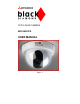
CCD COLOR CAMERA BDC4803VFD USER MANUAL Page : 1
CONTENTS CONTENTSbbbbbbbbbbbbbbbbbbbbbbbbbbbbbbbbbbbb - PRECAUTIONS……………………………………… Page 3 - PACKING CONTENTS...…………………………… Page 4 - 1. User Manual………………………..........……………… Page 4 - 2. Camera……………...……..............................………… Page 4 - 3. Adapter Cable…………….............................………… Page 4 - 4. Screws……………...……..............................………… Page 4 - FEATURES AND FUNCTIONS………………….… Page 5 - INSTALLATION…………………………………...… Page 6 - 1. Power connection………………..……………….
PRECAUTIONS 1. Do not attempt to disassemble the camera. There are no user serviceable parts inside. Ask a qualified service person for servicing 2. Handle the camera with care. Do not misshandle the camera. Avoid striking, shaking, etc. Improper handling or storage could damage the camera. 3. Do not expose the camera to rain or moisture, or try to operate it in wet areas. Turn the power off immediately and ask a qualified service person for servicing. Moisture can damage the camera. 4.
PACKING CONTENTS CONTENTS PACKING 1. Usermanual 2. Camera 3. Adapter Cable 4.
FEATURES AND FUNCTIONS F - Auto Light Control (ALC) function - Electronic Light Control (ELC) function - Automatic Gain Control (AGC) function - Automatic Tracing White Balance (ATW) function - Internal Synchronisation - Minimum Illumination of 1 Lux @ F2.0 - Signal to noise ratio > 45 dB (AGC off) - Horizontal resolution of 480 TV lines. - OLPF Built in Unlike usual cameras, this camera filters unnecessary noise signals in dark view and transmits them with more clear picture signals.
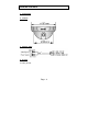
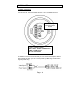
INSTALLATION I 1. Power connection Connect the DC 12V powercable with the + 12V- and GND Terminal. Power– and Signal Terminal camera bottom + 12V = +12V DC (±10%) GND = GND - Power + CVBS Shield CVBS = CVBS Signal NC = No Connection In addition to use the screw terminal you can connect the Adapter cable to this terminal and then you can connect power by NES Plug and the video signal by BNC Plug.
l Resistance of copper wire (at 20 °C) Copper wire size W/m 0,22 mm² 0,33 mm² 0,52 mm² 0,83 mm² 0,078 0,05 0,03 0,018 l Calculation of max. cable length between camera and power supply: 10,5V DC £ V – (R x 0,42 x L) £ 16V DC L : Cable length (m) R : Resistance of copper wire (W / m) V : DC output voltage of power supply (V DC) L standard = V - 12 / 0,42 x R L min. = V - 16 / 0,42 x R L max.
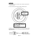
2. Video cable l It is recommended to use a monitor with a resolution at least equal to that of the camera. l Connect the Video cable with the CVBS and GND Terminal. Power– and Signal Terminal camera bottom + 12V = +12V DC (±10%) GND = GND - Power + CVBS Shield CVBS = CVBS Signal NC = No Connection In addition to use the screw terminal you can connect the Adapter cable to this terminal and then you can connect power by NES Plug and the video signal by BNC Plug.
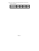
l The max. extensible coaxial cable length between camera and the monitor is shown below. Coax cable type Recommended max.
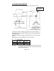
3. View angle and focus Adjustment Open the Dome Cover to adjust the angle of view (Zoom) and focus Zoom and Focus Adjustment To adjust focus and the viewing angle (Zoom) you have to loosen the adjustment lever by turning left, afterwards you can slide the adjustment lever right and left. Adjust at first the viewing angle and afterwards the focus to get a sharp picture. After adjustment fix the adjustment lever by turning right. Min. – max. viewing angle Max.
SSPECIFICATION Model Name Signal Standard Objective CCD – Chip Scanning System Scanning Frequency Total Pixels Effective Pixels Horizontal Resolution Electronic Shutter Automatic Iris Control S/N Ratio Sensitivity Sync System White Balance Function Video Output Power Source Power Consumption Operating Temperature Operating Humidity Dimensions (W x H x D mm) Weight (without Lens) Approvals BDC4803VFD PAL f : 4 – 8 mm 1/3” Super HAD CCD 2:1 Interlaced H: 15.625 kHz V: 50 Hz 795 (H) x 596 (V) app. 470.
ADDRESS (Technical specifications subject to change. No liability will be assumed for printing errors or other errors.