
User manual


3. WIRING
3-11
3
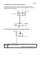
3.3.4 Wiring of the speed command input terminals
Use shielded or twisted shielded cables for wiring. Connect one shield sheath to
the terminal 5. Leave the other shield sheath open.
The following diagram shows the wiring of the terminal 2.
The same wiring also applies to the other terminals.
Drive unit
10
2
5
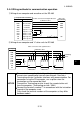
3.3.5 Wiring of the transistor output terminals
The terminal SE is a common terminal.
RUN
FU
SE
1
2
9
R
R
R
R
DC24V
Drive unit
When driving a coil load such as a relay coil, always connect the following diode.
Connect the diode with correct polarity. Opposite polarity will cause the drive unit
to fail.
Drive unit
DC24V
RUN
SE
Relay
NOTICE
Terminal SE is isolated from terminals SD and 5. Do not connect
them each other.