
- Mitsubishi Digital Electronics VCR User Manual


83
8. Printing Procedures (Special prints)
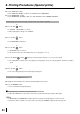
TIMING CHART
Input signal level : TTL
Input timing : 1 word 38.4 ms
Example: print code = 13=010011
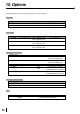
External REMOTE 1 terminal on the rear panel
• The pin number on the positive pin is shown below.
1 External remote terminal Signal allocation Connector REMOTE 1
Pin No.
1
2
3
Function
Ground
MEMORY
BUSY
Description
Earth
Memory: When the signal becomes “LOW” from “HIGH”, the image is stored
in memory. (When the signal has been “LOW” for 60msec. or more, the image
is stored in memory.)
When “REMOTE BUSY” is set to “HIGH”
“HIGH” : The VCP cannot accept the remote signal.
“LOW” : The VCP can accept the remote signal.
The signal becomes “HIGH” in the following cases;
(1) During initialization after the VCP has been switched on
(2) For about 1 sec. after the INPUT SELECT switch has been set
(3) During displaying the menu screen
(4) When the image cannot be stored in memory
1.6 ms
0.4 ms
Input timing : Code : “0”
3.2 ms
0.4 ms
Input timing : Code : “1”
110010
132
1
3
2