COLOUR VIDEO COPY PROCESSOR MODEL CP900E OPERATION MANUAL THIS OPERATION MANUAL IS IMPORTANT TO YOU. PLEASE READ IT BEFORE USING YOUR COLOUR VIDEO COPY PROCESSOR. This video copy processor complies with the requirements of the EC Directive 89/336/EEC, 73/23/EEC, 93/42/EEC and 93/68/EEC.
CONTENTS Contents ................................................................................................ Safety precautions ................................................................................ Special features .................................................................................... Unpacking ............................................................................................. Features and functions ....................................................................
SAFETY PRECAUTIONS In the interest of safety, please observe the following precautions: POWER REQUIREMENT PRECAUTIONS This Colour Video Copy Processor is designed for operation on 220-240V, 50Hz AC. Never connect to any outlet or power supply having a different voltage or frequency. WARNING: THIS APPARATUS MUST BE EARTHED. AVERTISSEMENT: CET APPAREIL DOIT ETRE MIS A LA TERRE. FEATURES PROTECTIVE MEASURES IF ABNORMALITIES ARISE, ....
SAFETY PRECAUTIONS INSTALLATION LOCATIONS MAINTAIN GOOD VENTILATION Ventilation slots and holes are provided on this unit. Place the unit on a hard and level surface and locate at least 10 cm from walls to insure proper ventilation. When putting the unit on the system rack, take a space between the unit and the back of the rack. UNSUITABLE LOCATIONS Avoid shaky places or hot-springs areas where hydrogen sulfide and acidic ions are likely to be generated.
TECHNICAL DESCRIPTIONS PRECAUTIONS The supplier will make available on request such circuit diagrams, component part lists, descriptions, calibration instructions or other information which will assist the USER’s appropriately qualified technical personnel to repair those parts of the EQUIPMENT which are classified by the manufacturer as repairable.
SPECIAL FEATURES SPECIAL FEATURES AVAILABLE IN VARIOUS MEDICAL FIELDS, INCLUDING ENDOSCOPY DIAGNOSIS 3 kinds of colouring characteristics (gamma curve) are employed, which are the best for medical diagnostic devices, including endoscope requiring precise images and ultrasound diagnostic equipment etc. The colour is reproducible for each diagnostic equipment with easy operation. Each gamma curve is adjustable for each user flexibly.
UNPACKING UNPACKING PRECAUTIONS Take the unit out of the box by the following procedures. Make sure to check the contents. Open the top of the box. 2 Remove the cushion with contents. 3 Take the unit out of the box carefully. 4 Unwrap the packing. O R DE O V I SS UR CE LO RO C O PY P CO 1 FEATURES O R DE O VI SS UR CE LO PRO CO PY CO Be careful not to drop the contents. CONNECTIONS PREPARATION Make sure to keep the unit horizontally.
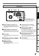
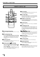
FEATURES & FUNCTIONS FRONT PANEL 2 3 45 6 7 8 1 D 9 A B C 1 POWER BUTTON(INDICATOR) 7 MEMORY BUTTON 2 LCD (LIQUID CRYSTAL DISPLAY) 8 PRINT BUTTON 3 MENU BUTTON 9 PRINT OUTLET Press to turn on power. Press again to turn off power. When the power is turned on, the indicator illuminates. Indicates input signal settings and various function modes and settings. Use Menu on the monitor or LCD for setting functions. See pages 36 - 37. Press for colour adjustment.
1 2 REMOTE 3 4 6 S-VIDEO IN RGB VIDEO 75Ω/HIGH 75Ω HIGH IMPEDANCE S-VIDEO OUT R G/G+SYNC B IN 7 OUT 8 FEATURES RS-232C 5 PRECAUTIONS REAR PANEL Y/SYNC 75Ω/HIGH 75Ω HIGH SYNC AC LINE 9 75Ω HIGH 1 REMOTE TERMINAL 2 (MINI DIN 8 PIN) Memorizing images and printing is available by the remote signal inputted through this terminal. It is necessary to make a circuit for remote control unit to use the function. See pages 32-33.
FEATURES & FUNCTIONS REMOTE CONTROL UNIT 1 2 5 SET BUTTON DISPLAY 9 COLOR ADJUST PROG. FIELD /FRAME 6 STOP BUTTONS 4 Press to cancel the printing process and start mechanical initializing. When pressing these buttons during displaying MAIN MENU, SERVICE MENU will be displayed. PRINT Q' ty MENU SET CLEAR 5 7 MEMORY PAGE BUTTON STOP 12 13 14 3 + - 10 11 Press to go to SAVE PRG. Repress to memorize the values and exit the MENU mode. See page 34-35.
CONNECTIONS PRECAUTIONS The functions of this unit can be set by the menu screens displayed on the monitor. • Connection with a monitor • Connection with VIDEO/S-VIDEO signal equipment • Connection with RGB analog signal equipment • Connection with RS-232C equipment Connect this unit with a monitor to check the images to be printed and the images stored in memory. The following examples show the connections with a video signal, S-video signal,RGB analog signal and RS-232C equipment.
CONNECTIONS 3 Press 4 Press } button to select INPUT menu. ] button. INPUT menu is displayed. Set the monitor polarity with “IN SYNC” on this menu. 5 Press { or } button to select “IN SYNC”. The sync. signal level being selected, for example, “ttl” is displayed. 6 Set the sync. signal level according to the equipment to be connected. Press [ or ] button to select “ttl”, “sog” or “0.3v”. ttl sog 0.3v Inputs the TTL level sync signal. Inputs the Sync. On Green level sync signal. Inputs the 0.
F Press { or } button to select “RGB SOG ”. [ or ] button to select “on” or “off”. PRECAUTIONS E Press FEATURES You can select whether Sync. ON Green signal is added to the output signal or not. When “on” is selected, Sync. ON Green signal is output and when “off” is selected, only Green signal is output. Select “on” or “off” according to the monitor to be connected. off Only Green signal is output. on Sync. On Green signal is output. G Press SET button.
CONNECTIONS CONNECTION WITH RGB ANALOG SIGNAL EQUIPMENT Make sure to turn off the power before setting. (EXAMPLE) RGB analog signal equipment To RGB analog input terminals ( SCAN START ) 75Ω/HIGH 75Ω HIGH IMPEDANCE S-VIDEO OUT IN R G/G+SYNC B n c RESET WHITE BALANCE / G/G+SYNC. S-VIDEO IN RGB VIDEO . BRIGHTNESS b x BLUE z R RS-232C SCAN SPEED OFF H+V-SYNC. REMOTE v 10 KEY POWER ON B VCP , GREEN REPLAY Connection is not required for SYNC ON G CONTRAST RED m H+V-SYNC.
PRECAUTIONS CONNECTION WITH RS-232C EQUIPMENT This unit can controlled through a RS-232C port with custom software. (Image data can not be input.) For the protocol, consult your dealer. Make sure to turn off the power before setting. 2 RS-232C TERMINAL SIGNAL 1 25 14 FEATURES Pin number 13 To RS-232C terminal (RS-232C) To RS-232C treminal RS-232C S-VIDEO IN RGB VIDEO R G/G+SYNC IMPEDANCE Pin No.
CONNECTIONS 4 Press ] button. RS232C menu is displayed. Set “BAUD RATE” on this menu. 5 Press { or } button to select “BAUD RATE”. The setting BAUD RATE (e.g. 1200) will be displayed. 6 Press or ] button to select “1200”, “2400”, “4800” or “9600” (bit/s). 7 Press 8 Press [ { or } button to select “COMMAND TYPE”. [ or ] button to select “a” , “b” or “c” . Select “a” for normal setting. Depending on the connected equipment, select “b” or “c”. 9 Press SET button. SERVICE MENU is displayed.
BEFORE OPERATION PRECAUTIONS Before printing, 1. Unlock the printing unit. (See below) 2. Install the print paper and ink cassette. (pages 17-21) PAPER SHEET SET When using this unit for printing, make sure to use the following types of paper sheet and ink sheet set.
BEFORE OPERATION 2 INSTALLATION OF PRINT PAPER Do not remove the seal on the print paper yet. When using thermal paper, remove the seal as shown on the previous page. Gear Seal 1 Insert the print paper roller with gear on the left. Press the folder 2 1 as shown right, and set the print paper roller. 1 Front side 2 Set the other side of roller without gear.
2 PRECAUTIONS ON SETTING THERMAL PAPER PRECAUTIONS When setting the thermal paper, observe the following precautions to prevent paper jam. • Do not use defective paper. Do not use the bent or wrinkled paper. • Adjust the paper position correctly. FEATURES When the paper is fed out skewed from the print exit, adjust the paper position so that it is fed out straight. • Do not slack the roll paper. Set the paper tightly to remove any slack. CONNECTIONS PREPARATION • Make the paper side even.
BEFORE OPERATION • NOTE Do not remove the IC chip or IC holder from the ink sheet. Removal of the IC will stop the printer from functioning correctly. • Set the projected part of the IC holder to the correct position as shown below. IC holder Projected part 2 INSTALLING THE INK CASSETTE 1 Eliminate any slack of the ink sheet. Hold the colored roller and turn the white roller. 2 Insert the ink cassette with the ink sheet into its compartment.
• • PRECAUTIONS • 3 4 NOTE Make sure to press MONITOR button first for operating and . Pressing MEMORY button first operates to memorize the images. When exchanging the printing paper or ink cassette during using the unit, the recorded images may be erased by pressing MEMORY button first. Do not feed the print paper more than 2 times. Doing so will not allow the number of prints indicated on page 17 to be printed. When thermal paper is running out, red lines appear on both sides of the paper.
PRINTING (BASIC) BEFORE PRINTING DISPLAY PROG. COLOR ADJUST FIELD /FRAME 2 SELECTING FIELD/FRAME PRINT Q' ty MENU Press FIELD/FRAME button on the remote control unit to select “FIELD” or “FRAME”. • Select “FRAME” for a high resolution still image printing. • Select “FIELD” for a picture of quickly moving objects. When “FIELD” is selected, the print image will be lower in resolution. • The selected mode is displayed on the monitor screen and LCD of this unit.
memorize the setting. The program is replaced. In case of keeping the stored program, do not select the program number in which the setting is stored. 6 Press SET button. PRECAUTIONS 5 Press [, ] button to select one of the program number (1-3) to MAIN MENU INPUT VIDEO / S-VIDEO / RGB COLOR ADJ LAYOUT PRINT COMMENT MEMORY POSITION SAVE PRG 1 / 2 / 3 / CANCEL The source image is displayed. FEATURES The selecting of input signal is completed.
PRINTING (BASIC) 5 Press SET button. • • MAIN MENU is displayed. “SAVE PRG 1/2/3/CANCEL” is selected. • This menu lets you select a program memory (1-3) to store your new settings. 6 Press [, ] button to select one of the program memory (1-3) to memorize the setting. The program is replaced. In case of keeping the stored program, do not select the memory number in which the setting is stored. When “CANCEL” is selected, the settings are not memorized.
2 MEMORIZING AND PRINTING AN IMAGE • PRECAUTIONS 1 Display the image which you wish to print. The memory page can be changed by pressing MEMORY PAGE button on the remote control unit. 2 Press MEMORY button. The selected page is shown in yellow. • When pressing MONITOR button to show “MEMORY” on monitor display, the image on the selected memory page will be displayed on monitor. FEATURES • 3 Press PRINT button. • • The image displayed on the monitor will be printed.
PRINTING (BASIC) 2 NUMBER OF MEMORY PAGES As this unit has 1280 pixel x 600 lines x 3 frames of memory, the following memory operations are available.
2 MULTIPLE COPY OR CONTINUOUS PRINTING printing until the paper or ink sheet is used up. Multiple quantity printing can be cancelled if needed. No. of print setting PRG. 1 Q'ty 1 1 Press PRINT Q’ty {,} button to set the number of sheets to be VIDEO The number of prints is displayed on the monitor screen. The number will increase by pressing PRINT Q’ty and decrease by pressing • PRINT Q’ty . The number switches in the order of; [ABC]FRAME LIVE FEATURES printed.
PRINTING (SPECIAL) Various types of printing are available by setting on the menu screen (MAIN MENU and SERVICE MENU). In this section, some examples of special prints are given. For each setting, see pages 34-37. MULTI PRINT MULTI PRINT is the function which 2, 4 or 16 images can be printed on a sheet. Use LAYOUT of MAIN MENU for setting. For the setting, refer to page 40-41. For PHOTO1 setting, refer to “Photo print” on page 30.
2 WHEN SETTING TO MODE : DIFF, IMAGES :4; PRECAUTIONS Repeat the following procedure to store the set number of images in memory. 1 Press DISPLAY button to display the set condition. 2 Press MONITOR button and select the source image (“LIVE” is displayed on the monitor.) to display the image to be stored. • FEATURES 3 Press MEMORY button to store the image to be printed.
PRINTING (SPECIAL) SEPARATE PRINT • • The SEPARATE print is a function to insert a white frame between 2 or more images. Use LAYOUT2 of SERVICE MENU for setting. See page 48. NOTE The amount of white frame in multi print is different between on the monitor and the printed image. The image size changes according to “SIZE” of LAYOUT menu. The setting just before printing applies to all the multi print images.
The image can be stored in memory by sending the remote signal through the external remote terminal on the rear panel. When the MEM&PRN(MEMORY & PRINT) function is set to ON, the image will be printed after being stored in memory. • Make out the necessary circuit to use this function by referring to the following. JACK) Pin No. 1 2 BUSY1 Description Earth Memory : When the signal becomes “LOW” from “HIGH”, the image is stored in memory.
PRINTING (SPECIAL) EXTERNAL REMOTE TERMINAL 2 12 The image can be stored in memory and printed by sending the remote signal through the external remote terminal on the rear panel. • Make out the necessary circuit to use this function by referring to the following. 2 EXTERNAL REMOTE TERMINAL SIGNAL ALLOCATION (MINI 34 67 8 DIN8PIN) Pin No. 1 2 Function Description Ground MEMORY Earth Memory : When the signal becomes “LOW” from “HIGH”, the Pin No. Circuit inside the VCP image is stored in memory.
PRECAUTIONS 2 PIN NO. 6 REMOTE TERMINAL 1.6 ms (T2) By sending the following remote control codes from pin No.6, the same functions as the wired remote control unit supplied can be controlled. 01: [ button 02: { ] button 03: } button 04: { button 0C: PRINT Q’ty 0D* 0E*: SET button 12*: PROGRAM button 13*: PRINT button 0F*: STOP button 15*: FIELD/FRAME button 16*: COLOR ADJ button 17*: MEMORY button 1C*: MEMORY PAGE button 18*: DISPLAY button 1D*: MONITOR button 0.4 ms (T1) } button 3.
SETTING THE FUNCTIONS (MENU CHART) MONITOR DISPLAY CHART COLOR ADJ SELECT COLOR/B&W BRT : 0 CONT : 0 R-SUB : 0 C G-SUB : 0 M B-SUB : 0 Y CENTER CANCEL OPERATION p is reference page. Press [ , ] button to change the value, select the mode or switch the item. R G B Select an item with { ,} button. Monitor display is the name of button on remote control unit. is the name of button on front panel. *1 When going back to MAIN MENU or SERVICE MENU without saving the setting, press MENU button.
System setting display SYSTEM SETUP INCREMENT OFF/PART/PAGE BUZZER OFF/T1/T2 REMAINING Q'ty 10 REMAIN NOTICE OFF/BZ/PRN/B&P REMAINING SCREEN OFF/ON ERROR SCREEN OFF/ON AUTO FEED&CUT OFF/ON THERMAL OFF/ON PAPER HOLD OFF/ON INIT PROG ALL/MAIN/SERVICE INITIALIZE OFF/GO[SET] Does not display when selecting THERMAL : ON Only OFF is available when selecting THERMAL : ON AUTO CUT OFF/ON is displayed when selecting THERMAL : ON p47 Gamma level setting display GAMMA ADJ INIT [CLEAR] COLOR ALL/EACH
SETTING THE FUNCTIONS (MENU CHART) LCD DISPLAY CHART OPERATION LCD display The menus in the broken lines are indicated by{ ,} button. MC:SELECT color p 0 0 0 0 0 [>] [>] BRT CONT R-SUB G-SUB B-SUB CENTER CANCEL is reference page. Press [ , ] buttons to change the value, select mode or switch the item. (The item indicated by switching is shown in light character in this chart.) is the name of button on remote control unit. is the name of button on front panel.
PRECAUTIONS p46 System setting display SS;INC off off 10 off off off off off off all off part page tone1 tone2 0~20 buz prn b&p on on on on on main ser go[set] Does not display when selecting THERMAL : on Only off is available when selecting THERMAL : on AUTO CUT off or on is displayed when selecting THERMAL : on Displays only when selecting COLOR:each p47 Gamma level setting display SG;COLOR Layout setting display 2 SL:PRN VAREA 0 SEPARATE MARGIN CUT off off all SELECT HI MID LOW POINT LOW P
ADJUSTMENTS & SETTINGS (MAIN MENU) MAIN MENU ITEMS MAIN MENU is used to open sub-menus. The functions are set with the following 6 menus. The settings can be saved by SAVE PRG.
5 Press [ or ] button to select an item or change value. “SAVE PRG 1/2/3/CANCEL” is displayed. This menu lets you select a program memory (1-3) to store your new settings. 7 Press AUTO/S OFF/OFF(PRN SELECT)/ON SAME/DIFF/PHOTO1 2/2S/4/16 W/M/N/USER OFF/W/M/N> 0 (0~ -48)> 0 (0~ -48)> 0 (0~ -63)> 0 (0~ -63)> FEATURES 6 Press SET button. LAYOUT MODE MULTI MODE IMAGES SIZE
ADJUSTMENTS & SETTINGS (MAIN MENU) COLOR ADJ Colour adjustment display • The colour of the source image and memorized image can be adjusted. SELECT COLOR B&W Selects colour print or black and white print. Colour print Black and white print (The monitor shows in colours.) BRT(Bright) Adjusts brightness of the printing image. (The whole image will be adjusted.) CONT (Contrast) Adjusts contrast of the printing image. (The image will be adjusted based on the black level.
IMAGES PRECAUTIONS MODE Selects print mode SAME Prints images of the same scenes on a sheet. DIFF (Different) Prints images of different scenes on a sheet. PHOTO1 Prints images in Photo mode. • This menu is displayed only when MULTI : ON is selected. Selects the number of images on a sheet. Is displayed when setting MULTI to “ON”. 2-images on a sheet. (2 S-size images can be printed in L size print. However, the top and bottom of the image will be clipped.) 2S 2 reduced images on a sheet.
ADJUSTMENTS & SETTINGS (MAIN MENU) PRINT Print setting display GRAD (Gradation) Adjusts the gamma curve of images. Selects the gamma curve among 3 kinds of the settings. ES Mainly when connecting to endoscope ECHO Mainly when connecting to ultrasound diagnostic equipment NOR Mainly when connecting to other equipment • Only NOR is available when using CK900S4P, CK900L4P, CK900S4P(HX)EU or CK900L4P(HX)EU or selecting THERMAL : ON.
PRECAUTIONS COMMENT Comment making display COMMENT OFF/ON[SET]/ADJ/DATA This menu is used to enter a comment. 1 Comment mode Selects to display the comment or not. Does not display the comment. ON[SET] Displays the comment. When pressing SET button during selecting ON, the editing display ADJ will be shown. Prints the set value made on APT, COLOR ADJ and ANALOG COLOR DATA ADJ menu.
ADJUSTMENTS & SETTINGS (MAIN MENU) 5 Repeat2steps 2 to 4 to complete a comment. • • • Skip if you do not change the cursor position. Only one comment can be stored regardless of the program number you chose in SAVE PRG. Same comment will be stored in PRG.1 through PRG3. Different comments cannot be stored in each program. When printing in FIELD mode, the comment is a little lower in quality.
ADJUSTMENTS & SETTINGS (SERVICE MENU) SYSTEM SERVICE MENU SYSTEM GAMMA ADJ LAYOUT 2 ANALOG COLOR ADJ INPUT OUTPUT KEY SET RS232C REMOTE PREVIOUS ERROR SAVE PRG 1 / 2 / 3 / CANCEL FEATURES Sets page increment, buzzer and remaining of ink sheet, selects thermal paper. GAMMA ADJ Sets gamma curve level. LAYOUT2 Adjusts print layout setting. ANALOG COLOR ADJ Adjusts analog input signal image. INPUT Sets even/odd number of FIELD, adjusts display, input signals, etc.
ADJUSTMENTS & SETTINGS (SERVICE MENU) SYSTEM SETUP System setting display INCREMENT OFF PART PAGE BUZZER OFF T1 T2 REMAINING Q’ty 0 ~20 Page increment is not available. Every time pressing MEMORY button, memory part goes to the next part and image will be memorized on it. The memory page does not go to the next. When MULTI:OFF, this mode works and same as PAGE mode. Every time pressing MEMORY button, memory page goes to the next page and image will be memorized on it.
• • • • Sets to hold the printed paper or not. Printed paper is cut and released. Printed paper is held at the print outlet after cut. Pull the paper out when necessary. When selecting THERMAL : ON, this menu changes to AUTO CUT. It is recommended not to leave the printed paper holding at the print outlet. Some malfunction may occur. Do not turn off the power while holding paper. When PAPER HOLD is set to ON, MENU button and COLOR ADJ button on the remote control unit are not avilable.
ADJUSTMENTS & SETTINGS (SERVICE MENU) Hi/Mid/Low Adjusts the colour depth of image by selected point. POINT(Hi/Mid/Low) Selects the point to adjust the colour depth. (EXAMPLE) Pointing lighter colour much lighter; Set the setting level for POINT(Hi) and Hi higher. NOTE It takes time to set the gamma value by CPU. Wait until the normal display is shown after pressing SET button. It may also take time to switch the program when the value of gamma setting is changed.
• Set this menu before memorizing image. FIELD The odd and even field lines will be reversed depending on the input interlaced signal. Printing image is not clear so that the odd INPUT FIELD AFC AGC DCF IN SYNC PRECAUTIONS INPUT Input signal setting display NOR/REV OFF/ON OFF/ON OFF/ON TTL/SOG/0.3V NOR(Normal) REV(Reverse) FEATURES and even field lines may be reversed depending on the input interlaced signal. In this case, FIELD is set to “REV”.
ADJUSTMENTS & SETTINGS (SERVICE MENU) OUTPUT Output signal setting display MONI R-SUB Adjusts red-subcontrast on the monitor. Red is added with ] and blue is added with [. MONI B-SUB Adjusts blue-subcontrast on the monitor. Blue is added with ] and yellow is added with [. LIVE SEL(Live select) ANA(Analog) DIG(Digital) CONVERT OUTPUT MONI R-SUB MONI B-SUB LIVE SEL CONVERT MEMORY SYNC OUT SYNC
after the image is stored in the memory. In case of multi image of different scenes, printing will be done after the last image is stored in OFF ON R1 OFF PART PAGE The next image is overlaid in the memory. The next image can not be overlaid in the memory when all parts of a page become full. To overlay a new image, print the memorized image. The next image can not be overlaid in the memory when all pages become full. To overlay a new image, print the memorized image.
ADJUSTMENTS & SETTINGS (SERVICE MENU) RS232C SET RS-232C signal setting display • This menu does not work when selecting THERMAL : ON or MULTI : OFF(PRN SELECT). BAUD RATE Set the baud rate of RS-232C. Set the baud according to the connecting device. COMMAND TYPE Sets the command type of RS-232C. Selects the command type of RS-232C to control this unit.
2 SYNCHRONOUS SETTING FOR MEMORY PRECAUTIONS STROBE : 1V, BUSY LEVEL: HIGH in REMOTE SET of SERVICE MENU V SYNC Image meorizing BUSY OUTPUT a a=approx.820 µsec. STROBE : 2V, BUSY LEVEL: HIGH in REMOTE SET of SERVICE MENU V SYNC FEATURES Image memorizing BUSY OUTPUT The numbers in the above figures are just references. The timing may be different according to the setting. CONNECTIONS PREPARATION PREVIOUS ERROR Error display This function displays the most recent types of error.
ERROR MESSAGES & COUNTERMEASURES ERROR MESSAGES If for some reason printing is not possible or error occurs during printing, the error message will be displayed on the monitor screen or LCD. In this case, follow the procedure described below. Error messages Causes DOOR OPEN The printing mechanism is not locked CHANGE PAPER completely. Paper is used up. Countermeasures • Insert the printing mechanism until it is locked in the unit. • Set a new roll of paper. Refer to pages 17-18.
BEFORE CALLING FOR SERVICE Use the following troubleshooting chart to try to resolve any apparent defect in operation. If you are unable to resolve the PRECAUTIONS 2 problem, unplug the power cord and contact your dealer. Symptom Check and Remedy No power (when POWER lamp does not illuminate) Is the power cord plug disconnected from the outlet? →Connect the power cord plug to the outlet firmly. No image appears on the monitor. FEATURES After tuning the power off, wait for approx. 2 minutes.
ERROR MESSAGES & COUNTERMEASURES Symptom Check and Remedy The stored image in the memory cannot be Is the S size ink sheet installed when selecting “S” in MODE : AUTO/S? Or enlarged to fill the maxim print area. is the L size ink sheet installed when selecting “AUTO” in MODE : AUTO/S? →Check the current setting. Refer to pages 23-24. Is the paper size set to “N” in the size setting in LAYOUT menu? →Set the size to “M” or “W”. Refer to pages 34, 41.
OVERCOMING PAPER JAMS PRECAUTIONS 1 Press OPEN button to pull out the printing mechanism. When it is not working, turn off the power once. Then try to press OPEN button again. FEATURES 2 Remove the ink cassette with ink sheet. CONNECTIONS PREPARATION 3 Remove the print paper as shown right. 2 1 4 Cut the defective part of the print paper with scissors. PRINTING 5 Cut both edges of the print paper. ADJUSTMENTS 6 Install the print paper. (Refer to pages 17-18.
CLEANING CLEANING A small amount of alcohol Cleaning as indicated below will help maintain stable printer operation and extend the printer’s life. Preparations Alcohol (isopropyl alcohol) Cleaning part How to hold tissue paper Tissue paper (Fold in half about 4 times, and use the folded side to clean.) Cotton buds Cleaning kit (Option)* Other : Cleaner pen (Option)* *Please ask the dealer about options. Cleaner pen (Option) Make sure to turn off the power before cleaning.
SPEC & OPTIONS SPECIFICATIONS PRECAUTIONS Class Model Printing method FEATURES Colour Video Copy Processor CP900E Sublimation Dye Thermal 3 colour faces progressive printing (yellow, magenta and cyan) and surface lamination Print quality Dot resolution Max. 1280 x 600 pixels (S size / FAST mode) Number of grades 256 (8 bits) for each colour ( About 16.7 million colours) Printing time* L size Approx. 22 sec./sheet (When using CK900L / 1-image/FAST mode) S size Approx. 12 sec.
Mitsubishi Electric Europe B.V. UK Branch Travellers Lane, Hatfield, Herts. AL10 8XB, England, U.K. Phone (1) 707 276100 FAX (1) 707 278755 German Branch Gothaer Strasse 8, Postfach 1548, 40880 Ratingen 1, Germany Phone (2102) 4860 FAX (2102) 486-732 French Branch 25, Boulevard des Bouvets - 92741 NANTERRE cedex Phone (01) 55.68.55.00 FAX (01) 55.68.57.