ENGLISH HC100 This User Manual is important to you. Please read it before using your projector.
CAUTION RISK OF ELECTRIC SHOCK DO NOT OPEN CAUTION: TO REDUCE THE RISK OF ELECTRIC SHOCK, DO NOT REMOVE COVER (OR BACK) NO USER-SERVICEABLE PARTS INSIDE REFER SERVICING TO QUALIFIED SERVICE PERSONNEL. The lightning flash with arrowhead symbol within an equilateral triangle is intended to alert the user to the presence of uninsulated “dangerous voltage” within the product’s enclosure that may be of sufficient magnitude to constitute a risk of electric shock.
Important safeguards ......................................................................................................................4 Preparating your projector ..............................................................................................................6 Using the remote control .................................................................................................................9 Setting up your projector...................................................................
Important safeguards Please read all these instructions regarding your projector and retain them for future reference. Follow all warnings and instructions marked on the projector. 10. Power sources This projector should be operated only from the type of power source indicated on the marking label. If you are not sure of the type of power, please consult your appliance dealer or local power company. 11.
Do not operate if smoke, strange noise or odor comes out of your projector. It might cause fire or electric shock. In this case, unplug immediately and contact your dealer. Never remove the cabinet. This projector contains high voltage circuitry. An inadvertent contact may result in an electric shock. Except as specifically explained in the Owner's Guide, do not attempt to service this product yourself. Please contact your dealer when you want to fix, adjust or inspect the projector.
Preparating your projector Checking accessories The following accessories are provided with this projector. Check to be sure that all of the accessories are packed in the package.
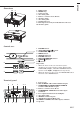
12 4 1 FOCUS ring 2 ZOOM ring 3 Control panel 4 Air outlet grille 5 Remote control sensor (Front) 6 Air inlet grille 7 Air outlet grille 8 Terminal board 9 Kensington Security Lock Standard connector 10 Air inlet grille 3 5 6 8 7 9 10 Control area 5 1 6 2 7 3 8 4 9 1 2 3 4 5 6 7 8 9 POWER button AUTO POSITION / { button COMPUTER / $ button MENU button STATUS indicator POWER indicator KEYSTONE/ENTER button VIDEO/ % button } button Important: • While the menu or the screen for the keystone ad
Preparating your projector (Continue) Bottom side 1 Adjustment foot (Front) 2 Lamp cover 3 Adjustment feet (Rear) 1 2 Caution: Do not replace the lamp immediately after using the projector because the lamp would be extremely hot and it may cause burns. 3 Remote control 15 ON POWER OFF 1 2 3 4 DVI-D (HDCP) COMPONENT DVI COMP VIDEO 14 13 S-VIDEO 12 COMPUTER PC 11 ENTER 5 MENU ASPECT 10 COLOR TEMP 6 7 C.T. AUTO POSITION A.P.
Operational range of the remote control • Keep the remote control photo-sensor out of direct sunlight or fluorescent lamp light. • Keep the remote control photo-sensor at least 2 m away from fluorescent lamps. Otherwise, the Rear of projector Front of projector remote control may malfunction. • If there is an inverter-operated fluorescent lamp near the remote control, the remote control operation may become unstable.
Setting up your projector Setting up the screen Install the screen perpendicularly to the projector. If the screen can not be installed in such a way, adjust the projection angle of the projector. (See below.) • Install the screen and projector so that the projector’s lens is placed at the same height and horizontal position of the screen center. • Do not install the screen where it is exposed to direct sunlight or lighting.
ENGLISH Screen size and projection distance Refer to the following table to determine the screen size. Center of the lens Hd B (Height of the projected image) Screen size A (Width of the projected image) D Projected distance (L) D B (Height of the projected image) Screen size (Height of the screen) C When the aspect ratio of the screen is 4:3, the positional relation between the projected image and the screen is as shown on the right. Refer to the following table for installation.
Viewing video images A. Connecting the projector to video equipment Preparations: • Make sure that the power of the projector and that of the video equipment are turned off.
Video player, or the like To audio output terminals 3 To video output terminal 4 COMPONENT VIDEO IN VIDEO 1 To terminal Audio/video cable 1. Connect one end (yellow) of the supplied audio/video cable to the VIDEO terminal of the projector. 2. Connect one end (white and red) of the supplied audio/ video cable to the audio input terminals (L/MONO, R) of the projector. 3. Connect the other end (yellow) of the audio/video cable to the video output terminal of the video equipment. 4.
Viewing video images (continued) Connecting to video equipment having a DVI-D terminal You can project high-quality images by connecting the DVI-D terminal of this projector to video equipment having a DVI-D output terminal. In addition, this projector supports HDCP and is able to receive encrypted digital video data that are output from DVD players.
ENGLISH C. Projecting images Preparation: • Remove the lens cap. • Turn on the power of the connected video equipment. FOCUS ring ON POWER OFF ON ( I ) button ZOOM ring DVI-D (HDCP) COMPONENT DVI COMP VIDEO COMPUTER S-VIDEO PC COMPONENT button VIDEO button S-VIDEO button ENTER MENU ASPECT COLOR TEMP POWER button POWER C.T. STATUS AUTO POSITION GAMMA VOLUME A.P. VIDEO button 1. Confirm the POWER indicator lights up red.
Viewing video images (continued) ON POWER OFF OFF ( ) button DVI-D (HDCP) COMPONENT DVI COMP VIDEO COMPUTER POWER button POWER STATUS S-VIDEO PC ENTER MENU ASPECT COLOR TEMP C.T. AUTO POSITION GAMMA VOLUME A.P. To stop projecting: 8. Press the POWER button on the projector or the OFF ( ) button on the remote control. • A confirmation message is displayed. • To cancel the procedure, leave the projector for a while or press the MENU button. 9.
You can change the aspect ratio of the input video signal (or the ratio of width to height of the image). Change the setting according to the type of the input video signal. 4:3 Original image size Projects images with an aspect ratio of 4:3 when the input signal is 4:3 image. EXPAND 16 : 9 Projects images with an aspect ratio of 16:9. Projects images in the CinemaScope size or Vista size together with subtitles.
Viewing computer images A. Connecting the projector to a computer Preparation: • Make sure that the power of the projector and that of the computer are turned off. • When connecting the projector to a desktop computer, disconnect the RGB cables that are connected to the monitor. For analog connection: 1. Connect one end of the supplied RGB cable to the COMCOMPUTER IN/ PUTER IN/COMPONENT VIDEO IN terminal of the COMPONENT VIDEO IN projector. 1 2 to monitor port RGB cable COMPONENT VIDEO IN 2.
ENGLISH C. Projecting images Preparation: • Remove the lens cap. • Turn on the power of the connected computer. FOCUS ring ON POWER OFF ON ( I ) button DVI-D(HDCP) button COMPUTER button ZOOM ring DVI-D (HDCP) COMPONENT DVI COMP VIDEO COMPUTER S-VIDEO PC ENTER MENU POWER button ASPECT COLOR TEMP POWER STATUS C.T. AUTO POSITION GAMMA VOLUME A.P. COMPUTER button 1. Confirm the POWER indicator lights up red.
Viewing computer images (continued) ON POWER OFF OFF ( ) button DVI-D (HDCP) COMPONENT DVI COMP VIDEO COMPUTER POWER button POWER STATUS S-VIDEO PC ENTER MENU ASPECT COLOR TEMP C.T. AUTO POSITION GAMMA VOLUME A.P. To stop projecting: 8. Press the POWER button on the projector or the OFF ( ) button on the remote control. • A confirmation message is displayed. • To cancel the procedure, leave the projector for a while or press the MENU button. 9.
ENGLISH Menu operation • Menus are not displayed when no signal is supplied to the projector. IMAGE CONTRAST BRIGHTNESS CineRichColor *1 sRGB COLOR TEMP. *1 *1 COLOR TINT *1 *2 *2 SHARPNESS GAMMA MODE *1 INSTALLATION KEYSTONE AUTO POWER ON AUTO POWER OFF SPLASH SCREEN BACK COLOR LAMP MODE IMAGE REVERSE FEATURE MENU POSITION CINEMA MODE *3 VIDEO SIGNAL *4 *2 ASPECT PASSWORD FUNCTION LANGUAGE RESET ALL SIGNAL HORIZ.POSITION*7 VERT.POSITION *7 *6 FINE SYNC.
Menu operation (continued) Available settings in the menus Set the following items on their relevant menus. 1. IMAGE menu opt. 2.INSTALLATION menu opt. SVGA60 IMAGE 0 KEYSTONE BRIGHTNESS 0 CineRichColor AUTO AUTO POWER ON AUTO POWER OFF sRGB COLOR TEMP. OFF ON 6200K SPLASH SCREEN BACK COLOR COLOR 0 LAMP MODE TINT 0 IMAGE REVERSE SHARPNESS 0 GAMMA MODE opt. MENU POSITION 0 OFF OFF ? ON OFF AË opt. SVGA60 SIGNAL 1. HORIZ. POSITION 0 CINEMA MODE AUTO VERT.
VIDEO SIGNAL ASPECT OFF 8 positions AUTO 4:3 16:9 EXPAND PASSWORD FUNCTION LANGUAGE RESET ALL 10 languages 4. SIGNAL Menu ITEM SETTING HORIZ. POSITION * VERT. POSITION * FINE SYNC. TRACKING COMPUTER INPUT RGB YCBCR/YPBPR SET UP OFF 3.5%/7.5% HOLD USER CLAMP POSITION/ CLAMP WIDTH LPF • • • • FUNCTION Use to change the position of the menu. The film mode will be automatically activated when a film source signal is inputted. The film mode will not be activated.
Adjusting projected images To adjust the brightness (CONTRAST and BRIGHTNESS): You can make adjustments for the brightness of the projected image using the menu. (See Page 21 for menu setting.) 1. Display the IMAGE menu. 2. Select CONTRAST or BRIGHTNESS by pressing the { or } button. 3. Adjust the selected item by pressing the $ or % button. To cancel the menu: 4. Press the MENU button. CONTRAST Select to adjust the contrast of the image.
ENGLISH To adjust the tone of white (COLOR TEMP.): You can select a preset color temperature (white tone) using the menu. (See Page 21 for menu setting.) 1. Display the IMAGE menu. 2. Select COLOR TEMP. by pressing the { or } button. 3. Select your desired color temperature by pressing the { or } button. To cancel the menu: 4. Press the MENU button.
Adjusting projected images (continued) This projector automatically and properly projects video signals supplied from the computer. However, some video signals may not be projected, depending on the type of the computer. In such a case, press the AUTO POSITION button. (See Page 20.) When the signal is still not projected properly, adjust the projected image using the SIGNAL menu. How to adjust the image supplied from the computer using the menu: Carry out the following procedures according to the symptoms.
Password function This projector is equipped with the password function that is designed for wrong operation by children and restriction on operation by other than specified users. MENU ACCESS ............ All the buttons except for the POWER button on the projector are disabled. (The buttons on the remote control are enabled.) You can use this mode as a measure of prevention of wrong operation by children and restriction on operation by other than specified users. To enable the password function: 1.
Replacing the lamp This projector is equipped with a lamp to project images. This lamp is a consumable. It may burn out or its brightness may decrease during use. In such cases, replace the lamp with a new one as soon as possible. Be sure to replace the lamp with a new lamp separately sold that is exclusive to this projector. Contact your dealer for purchase of the lamp. WARNING: • Be careful not to drop the lamp fixing screws into the inside of the projector.
ENGLISH To replace the lamp: 1. Reverse the projector gently. (b) (a) 2. Loosen the screw (a) using a Phillips screwdriver (+), and remove the lamp cover (b). 3. Loosen the screws (c) using a Phillips screwdriver (+). 4. Pull up the handle. 5. Pull out the lamp box by the handle while holding the projector. • Pull the lamp box out of the projector slowly. If it is pulled out quickly, the lamp may break scattering glass fragments.
Asking for installation To view images projected by the ceilingmounted projector from the front: When the projector is installed on the ceiling, the special ceiling mount bracket, which is separately sold, is required. Be sure to ask a certified installation specialist for installation of the projector. Contact your dealer for details.
Before asking for repair of the projector, check the following. If the symptom persists, stop using the projector, be sure to unplug the power plug, and then contact your dealer. No image appears on the screen. Problem Solution Power can not be turned on. • Check whether the indicators are on or off and how they are lightning. POWER STATUS Off Off Solution • Connect the power cord to the projector. • Plug the power cord into a wall outlet.
Troubleshooting (continued) No image appears on the screen. (Continued) Problem Solution "NO SIGNAL" is displayed. • Turn on the power of the connected device, or check whether there is something wrong with the connected device. • Check whether the external device outputs signals. (Check this especially when the external device is a notebook computer.) • Check that the cable connected to the external device isn't defective.
ENGLISH Others Problem Solution The exhaust vents emit warm air. • This air comes out after cooling the inside of the projector. You may feel hot, but this is not a malfunction. No audio is output. • Check that the volume isn't set to low. The menu can't be used. • The microcomputers inside the projector may be wrongly operating because of noise. ➔ Press the POWER button to turn off the lamp and unplug the power cord from the wall outlet. Wait about 10 minutes, plug the power cord in, and try again.
Indicators This projector has two indicators, each of which shows the operation condition of the projector. The following offer solutions to possible problems. If these problem persist, turn the projector off and consult your dealer. POWER indicator STATUS indicator Normal condition POWER STATUS Steady red Off Steady green Blinking green Steady green Steady green CONDITION NOTE Stand-by Lamp stand-by (about 1 minute) The POWER button cannot be used to switch between on and off. The power is on.
The specifications and outside appearance of the projector are subject to change without prior notice. DLP™ projector HC100 0.55-inch Single chip DMD (Aspect ratio 16:9) Pixel 854 x 480 = 409920 pixels F 2.4 - 2.7 f= 19 - 23 mm Projection lens 200 W Light-source lamp 40" min. to 300" max. (Projection distance 1.4 to 10.
Specifications (continued) Specification of RGB signals in each computer mode of the projector Signal mode Resolution (H x V) – – – – – – – – 640 x 400 640 x 400 640 x 400 640 x 480 640 x 480 640 x 480 640 x 480 800 x 600 800 x 600 800 x 600 800 x 600 800 x 600 1024 x 768 1024 x 768 1024 x 768 1024 x 768 640 x 480 832 x 624 1024 x 768 1024 x 768 TV60, 480i(525i) TV50, 576i(625i) 1080i 60 (1125i 60) 1080i 50 (1125i 50) 480p (525p) 576p (625p) 720p 60 (750p 60) 720p 50 (750p 50) PC98 CGA84 CGA85 VGA60 VGA72
MITSUBISHI Projector Contact Information North America Asia MESCA (Mitsubishi Electric Sales Canada Inc.) http://www.mitsubishielectric.ca Information Technologies Group, 4299 14th Avenue, Markham, Ontario L3R 0J2, Canada Sales Phone :+1-(905) 475-7728 Fax :+1-(905) 475-7958 E-mail :projectors@mitsubishielectric.ca Technical Phone :+1-(905) 475-7728 Fax :+1-(905) 475-7958 Customer Care E-mail :support@mitsubishielectric.