
- Mitsubishi Digital Electronics DVR User Manual

22
••••••••••••••••••••••••••••••••••••••••••••••••••••••••••••••••••••••••••••••••••••••••••••••••••••••••••••••••••••••••••••••••••••••••••••
•
/ Initial settings
AUTO SET UP (continued)
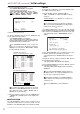
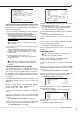
8. Turn the SHUTTLE ring clockwise.
• The <AUTO RECORD SETTING> screen appears.
• The period of the record can be set.
• Setting of AUTO RECORD SETTING ( default : “24H” )
“24H”, “48H”, “72H”, “96H”, “120H”, “144H”, “1WEEK”,
“2WEEK”, “3WEEK”, “1MONTH”, “2MONTH”, “3MONTH”,
“4MONTH”, “5MONTH”, “6MONTH”, “1YEAR”
<AUTO RECORD SETTING>
>>
RECORDING CYCLE 24H
EXECUTE
JOG :SELECT
SHUTTLE>>:EXECUTE
9. Repeat steps 3 and 4 to set.
10. Turn the JOG dial to move the cursor to “EXECUTE”, and
turn the SHUTTLE ring clockwise.
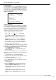
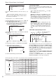
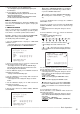
• The <RECORD SETTING> screen appears.
• The recording interval and recording picture quality of
normal recording and alarm recording corresponding to each
camera numbers can be set in this screen.
The <RECORD SETTING> screen consists of 2
pages. The second page is displayed by turning the
JOG dial to move the cursor to “NEXT PAGE”, and turn
the SHUTTLE ring clockwise.
9
7
4
5
6
1
2
3
8
<RECORD SETTING>
ALARM
NO PPS GRADE A-PPS A-GRADE
>>
15P SUPER 15P SUPER
------ SUPER ------ SUPER
------ SUPER ------ SUPER
15P SUPER 15P SUPER
------ SUPER ------ SUPER
------ SUPER ------ SUPER
------ SUPER ------ SUPER
------ SUPER ------ SUPER
------ SUPER ------ SUPER
NEXT PAGE
<RECORD SETTING> 1/2
Camera selection during alarm recording
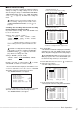
<RECORD SETTING> 2/2
10
11
13
14
15
16
12
<RECORD SETTING> ALARM
NO PPS GRADE A-PPS A-GRADE
>>
------ SUPER ------ SUPER
15P SUPER 15P SUPER
------ SUPER ------ SUPER
------ SUPER ------ SUPER
15P SUPER 15P SUPER
------ SUPER ------ SUPER
------ SUPER ------ SUPER
<ESTD REC> D H M
PRESS POWER BUTTON TO EXIT
According to the number of the cameras connected
and the value of “RECORDING CYCLE”, the most suit-
able setting of the “PPS”, “A-PPS”, “GRADE” and “A-
GRADE” are set automatically.
11. When the setting is complete, press the POWER button.
• “SETTING UP...” is displayed on the screen, and the unit
starts-up.
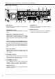
■ INITIALIZATION
The <INITIALIZATION> setting is used to select the mode of
peripheral recording devices connected to SCSI connector
ID4•ID5, to make HDD SETTING, and to initialize the HDD.
♦ ID4•ID5
The peripheral recording device connected to ID4•ID5 can be
set to HDD or Archive/Copy device.
Setting of “ID4•ID5” ( default : “ARCHIVE•COPY” )
“HDD” : Set ID4•ID5 to recognize the HDD for capacity
expansion.
“ARCHIVE•COPY” : Set ID4•ID5 to recognize the
ARCHIVE•COPY device.
The maximum capacity for peripheral recording de-
vices connected to the SCSI will differ according to SCSI
number chart setting (
page 21).
1. Turn ON the MAIN switch on the rear of the unit, and wait
until the ACCESS indicator goes off. Hold down the REC/STOP
button, and press the POWER button on the front of the unit.
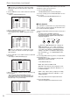
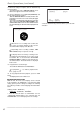
• The unit starts-up, and the <INITIALIZATION> screen is
appears.
<INITIALIZATION>
>>
ID4•ID5 ARCHIVE•COPY
HDD SETTING NORMAL
BOOT UP DELAY 30S
POWER OFF
INITIALIZATION
ALL DATA WILL BE ERASED
WHEN PROCEED INITIALIZATION
2. In the <INITIALIZATION> screen, confirm the cursor is next
to “ID4•ID5”, and turn the SHUTTLE ring clockwise.
• The background of the “ARCHIVE•COPY” turns red and
flashes.
3. Display the desired setting by turning the JOG dial, and
turn the SHUTTLE ring clockwise.
• The setting is made, and the display stops flashing.
4. Select “INITIALIZATION” by turning the JOG dial, and turn
the SHUTTLE ring clockwise.
• The setting is made, and the display returns to normal after
initialization.
Performing “INITIALIZATION” initializes all data on
the HDD. It deletes the complete ALARM LIST, and
the next entry is registered from 00001.
Changing the “ID4•ID5” from “ARCHIVE•COPY” to
“HDD”, and vice versa will cause the Timer program to
completely reset.
Select “POWER OFF” to abort initialization.