
- Mitsubishi Digital Electronics DVR User Manual

24
•••••••••••••••••••••••••••••••••••••••••••••••••••••••••••••••••••••••••••••••••••••••••••••••••••••••••••••••••••••••••••••••••••••••••••••
•
Basic Operations
■ Multiplexer functions
Buttons on the front of the unit can be used to perform
some of the multiplexer functions.
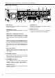
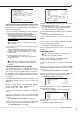
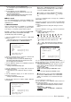
♦ Multiplexer buttons
MOVE buttons
2. SPLIT/SEQUENCE buttons
3. ZOOM button
1. Camera number buttons (1 to 16)
SPLIT/
SEQUENCE
ZOOM
16
0
1. Camera number buttons (1 to 16)
Video images of cameras connected to CAMERA IN ter-
minals 1 to 16 on the rear of the unit are displayed.
Live or pre-recorded video images of specific
channels are displayed when it’s camera button is
pressed.
2. SPLIT/SEQUENCE button
The screen switches in order of SPLIT16, 2 types of SPLIT9
SCREEN SETTING (a, b), 4 types of SPLIT4 SCREEN
SETTING (a, b, c and d), SPLIT9 SEQUENTIAL, SPLIT4
SEQUENTIAL, and SINGLE SEQUENTIAL set in the
<MPX DISPLAY SETTINGS> screen (SEQUENTIAL dis-
play is skipped during playback).
Pressing the OUTPUT B button on the front of
this unit can switch the operation of camera number
buttons and the SPLIT/SEQUENCE button to the
screen of the monitor connected to the OUTPUT B
connector. Pressing the OUTPUT A button can
switch to the screen of the monitor connected to
the OUTPUT A connector.
3. ZOOM button
When this button is pressed during single screen display,
magnification 100% screen appears and the magnifica-
tion center point (X) is displayed at the center. Pressing
the button again will switch the magnification to 200% and
then 400%. By pressing the MOVE buttons, the magnified
screen can be moved vertically/horizontally with the cen-
tre point as the axis (
see “ZOOM button operations”,
page 40).
When the ZOOM button is pressed, camera number
buttons 1 to 4 move the “X” in the display area.
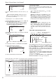
■ Menu settings
The operational conditions of this unit can be set via the
menu screens as needed. Although the method will differ
slightly depending on the menu screen, the basic setting
method of using the JOG dial and SHUTTLE ring will re-
main the same. e.g. setting the display mode.
SHUTTLE ring
JOG dial
Example : Set DISPLAY MODE to “3” ( default : “1” ).
1. Set the MAIN switch on the rear of the unit to ON. Press
the POWER button on the front after the ACCESS indicator
turns off.
• “SETTING UP...” appears on the screen and the unit is
booted.
• POWER button operation will not be accepted while the
ACCESS indicator is flashing. Press the POWER button after
the indicator turns off.
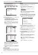
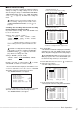
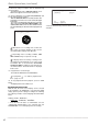
2. After boot-up, press the SET UP button inside the door on
the front of the unit.
• The <SETTINGS> screen appears.
<SETTINGS>
>>
TIME DATE/DISPLAY SETTINGS
MPX DISPLAY SETTINGS
MOTION DETECTION SETTINGS
RECORD SETTINGS
TIMER PROGRAM SETTINGS
INITIAL SET UP/INFORMATION
QUICK SETTINGS
MEMO:
When the SET UP button is pressed and the
menu screen appears, the background darkens and
the displayed characters become easier to see.
3. Check to see that the cursor (>>) is positioned at “TIME
DATE/DISPLAY SETTINGS”, and then turn the SHUTTLE ring
clockwise.
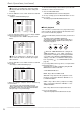
• The <TIME DATE/DISPLAY SETTINGS> screen appears (
see page 37).
<TIME DATE/DISPLAY SETTINGS>
>>
TIME DATE ADJUST
DISPLAY MODE 1
CLOCK LOCATION SETTING
CAMERA DISPLAY NUMBER
CAMERA TITLE/MEMO SETTING
DUPLEX MODE DISPLAY BOTTOM
<MODE 1>
01-01-2003 00:00:00
4. Turn the JOG dial to move the cursor to “DISPLAY MODE”
and turn the SHUTTLE ring clockwise.
• The background of the “DISPLAY MODE” setting turns red
and flashes.
Turning the JOG dial clockwise, the cursor (>>)
moves down. Turning counterclockwise, the cursor
(>>) moves up.
5. Turn the JOG dial to display “3”.
• The display mode sample on the bottom of the screen
changes to <MODE 3>.
6. Turn the SHUTTLE ring clockwise.
• The setting is confirmed and flashing stops.
• To continue with other settings, repeat steps 4 and 5.
Turning the SHUTTLE ring clockwise while the
setting is flashing, will keep the set settings.
To exit the screen, turn the SHUTTLE ring
counterclockwise.