
- Mitsubishi Digital Electronics DVR User Manual

47
••••••••••••••••••••••••••••••••••••••••••••••••••••••••••••••••••••••••••••••••••••••••••••••••••••••••••••••••••••••••••••
Operations
<RECORD SETTINGS>
■ Settings concerning normal recording and
alarm recording
This unit allows per camera independent settings for nor-
mal recording and alarm recording. By this, more detailed
settings are possible such as changing the recording inter-
vals of the camera inputting the alarm signals while main-
taining the normal recording settings of normal cameras.
Certain settings and mode changes are limited
during Alarm recording. Pressing the ALARM INTER-
RUPT button halts additional alarm inputs, and stops
recording.
During recording, the setting in the <RECORD
SETTING> screen cannot be changed.
When the cameras for recording has no input
video signal, a warning display of “NO SIGNAL” ap-
pears (for details,
see “Warnings and CALL OUT
output” pages 96, 97).
■ Recording mode settings for normal
recording and alarm recording
Setting of the camera number for normal recording and alarm
recording, the TRIGGER for alarm recording, the recording in-
tervals and recording picture quality for normal recording and
alarm recording and whether to perform pre-alarm recording
for alarm recording can be set here (for normal recording,
see “Basic manual recording” pages 27, 28). Pre-alarm record-
ing is a function to start recording before the ALARM IN termi-
nal on the rear of the unit is grounded or motion is detected (for
details concerning pre-alarm recording, see page 72).
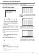
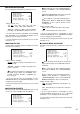
<RECORD SETTINGS>
>>
ALARM SETTING
RECORD SETTING
ALARM REC DURATION 5S
MOTION DET REC ALARM
ARCHIVE OVERWRITE OFF
ARCHIVE MEDIA AUTO EJECT OFF
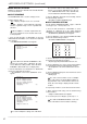
1. Press the SET UP button
}
<SETTINGS>
}
Select “ALARM
SETTING” in the <RECORD SETTINGS> screen and turn the
SHUTTLE ring clockwise.
• The <ALARM SETTING> screen appears.
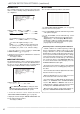
<ALARM SETTING>
ALARM RECORD CAMERA TRIGGER
>>
1 --------------- EXT
2 - -------------- EXT
3 -- ------------- EXT
4 --- ------------ EXT
5 ---- ----------- EXT
6 ----- ---------- EXT
7 ------ --------- EXT
8 ------- -------- EXT
9 -------- ------- EXT
NEXT PAGE SHUTTLE<<:BACK
9
7
4
5
6
1
2
3
8
<ALARM SETTING> 1/2
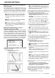
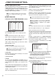
<ALARM SETTING> 2/2
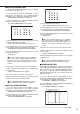
<ALARM SETTING>
ALARM RECORD CAMERA TRIGGER
>>
10 --------- ------ EXT
11 ---------- ----- EXT
12 ----------- ---- EXT
13 ------------ --- EXT
14 ------------- -- EXT
15 -------------- - EXT
16 --------------- EXT
EMR
SHUTTLE<<:BACK
10
10
11
11
13
14
14
15
15
16
16
12
12
10
10
11
11
13
14
14
15
15
16
16
12
12
9
7
4
5
6
1
2
3
8
The <ALARM SETTING> screen consists of 2
pages. The second page is displayed by turning the
JOG dial to move the cursor to “NEXT PAGE”, and
turn the SHUTTLE ring clockwise.
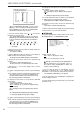
2. (When setting the alarm recording camera and trigger • • • )
Turn the JOG dial to select the desired alarm camera channel
number and turn the SHUTTLE ring clockwise.
• The first item from the left side in the “ALARM RECORD
CAMERA” setting display reverses in color.
• The camera numbers are lined in order of the number from
“
1
” to “
16
”.
• Multiple cameras can be entered to record when trigger.
When you turn the JOG dial counterclockwise, the
camera number setting or the TRIGGER setting will
reverses in color in order such as
1
, EXT,
16
,
15
• • • .
3. Turn the JOG dial to display the desired camera number
reversed in color and turn the SHUTTLE ring clockwise.
• The background of setting turns red and flashes.
While the setting is flashing, the setting screen can-
not be exited even when pressing the SET UP button.
4. Turn the JOG dial to display the desired setting and turn the
SHUTTLE ring clockwise.
• The setting is confirmed and flashing stops. Multiple camera
numbers can be selected for one alarm camera channel
number.
5. Turn the JOG dial clockwise to display “TRIGGER” setting
reversed in color and turn the SHUTTLE ring clockwise.
• The background of setting turns red and flashes.
6. Turn the JOG dial to display the desired setting and turn the
SHUTTLE ring clockwise.
• The setting is confirmed and flashing stops.
• Setting of “TRIGGER” ( default : “EXT” )
“EXT” : Alarm recording can only be started when the ALARM
IN terminal is grounded.
“MD&EXT” : Alarm recording can be started when the ALARM
IN terminal is grounded and the motion is detected
simultaneously.
“MD/EXT” : When the ALARM IN terminal is grounded or
motion is detected alarm recording is started.
“MD” : Alarm recording can only be started when the motion
is detected.
When you select and set the “TRIGGER” setting
to MD, MD/EXT or MD&EXT, the motion detection
function will be active and any setting changes can
not be accepted. Please use the ALARM INTER-
RUPT button to change the setting.
7. When the setting is complete, turn the SHUTTLE ring
counterclockwise.
• The cursor moves to the camera number on the left.
• When continuing with other camera number settings, turn
the JOG dial to move the cursor to the desired camera number
and repeat steps 2 ~ 7 to perform the settings.
8. (When setting the camera selection during alarm recording • • • )
Press the SET UP button
}
<SETTINGS>
}
Select “RECORD
SETTING” in the <RECORD SETTINGS> screen and turn the
SHUTTLE ring clockwise.
• The <RECORD SETTING> screen appears.