
- Mitsubishi Digital Electronics DVR User Manual


59
59
••••••••••••••••••••••••••••••••••••••••••••••••••••••••••••••••••••••••••••••••••••••••••••••••••••••••••••••••••••••••••••
Operations
1. Press the SET UP button
}
<SETTINGS>
}
Select
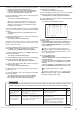
“COMMUNICATION PORT SETTINGS” in the <INITIAL SET UP/
INFORMATION> screen and turn the SHUTTLE ring clockwise.
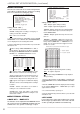
• The <COMMUNICATION PORT SETTINGS> screen appears.
<COMMUNICATION PORT SETTINGS>
>>
RS-232C
ETHERNET
♦ RS-232C
Settings for the communication device connected to this
unit is set.
• MODE
This unit can be controlled from a PC connected to the
RS-232C terminal. Comments can also be inputted from
a PC for recording of comments along with the video.
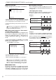
<RS-232C>
>>
MODE REMOTE A
SETTINGS
Setting ( default : “REMOTE A” )
“REMOTE A” : This unit can be controlled from a PC
and every status information is returned from the unit.
“REMOTE B” : This unit can be controlled from a PC
and from the unit when the status for command is
changed.
“REMOTE C” : This unit can be controlled from a PC
with no status information.
“OFF” : This unit cannot be controlled from a PC.
1. Press the SET UP button
}
<SETTINGS>
}
<INITIAL SET
UP/INFORMATION>
}
<COMMUNICATION PORT
SETTINGS>
}
Select “MODE” in the <RS-232C> screen.
Display the desired setting and confirm.
2. Turn the SHUTTLE ring counterclockwise or press the SET
UP button to exit.
• SETTINGS
RS-232C settings can be made when setting “MODE”
above to “REMOTE A”, “REMOTE B” or “REMOTE C”.
Set the settings for the RS-232C of the DVR and
PC the same.
Setting of “TRANSMISSION MODE” ( default : “9600” )
“1200”, “2400”, “4800”, “9600”, “19200”
Setting of “DATA BIT LENGTH” ( default : “8BIT” )
“8BIT”, “7BIT”
Setting of “PARITY BIT” ( default : “NONE” )
“NONE”, “ODD”, “EVEN”
Setting of “STOP BIT LENGTH” ( default : “1BIT” )
“1BIT”, “2BIT”
Setting of “DELIMITER” ( default : “CR” )
“CR”, “CR•LF”
1. Set “MODE” in the <RS-232C> screen to “REMOTE A”,
“REMOTE B” or “REMOTE C”.
2. Select “SETTINGS” and turn the SHUTTLE ring clockwise.
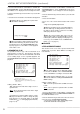
• The <RS-232C SETTINGS> screen appears.
<RS-232C SETTINGS>
>>
TRANSMISSION MODE 9600
DATA BIT LENGTH 8BIT
PARITY BIT NONE
STOP BIT LENGTH 1BIT
DELIMITER CR
3. Select the setting to change and turn the SHUTTLE ring
clockwise.
• The background of the setting turns red and flashes.
4. Display the desired sub item and turn the SHUTTLE ring
clockwise.
• The setting is confirmed and flashing stops.
5. To make additional changes, repeat steps 3 and 4.
6. Turn the SHUTTLE ring counterclockwise or press the SET
UP button to exit.
♦ ETHERNET
The IP address used to specify the connected recorder, sub
net mask setting, and MAC address are referenced below.
Do not assign “000.000.000.000” IP address. And
do not assign it as the broadcast address. If this ad-
dress were to be assigned, we could not guarantee
communications or any other functions of the recorder
unit.
1. Press the SET UP button
}
<SETTINGS>
}
<INITIAL SET
UP/INFORMATION>
}
Select “ETHERNET” in the
<COMMUNICATION PORT SETTINGS> screen and turn the
SHUTTLE ring clockwise.
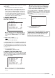
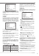
• The <ETHERNET> screen appears.
<ETHERNET>
>>
IP ADDRESS 192.168.000.100
SUB NET MASK 255.255.255.000
GATEWAY 000.000.000.000
E-MAIL ADDRESS
SERVICE PORT SETTING
ALARM NOTIFICATION SETTING
<MAC ADDRESS>
08-00-70-2E-3F-FF
PLEASE PRESS SET UP BUTTON
TO APPLY NEW SETTING
2. Select the setting you wish to alter by turning the JOG dial
and then turn the SHUTTLE ring clockwise.
• The left most number of the setting will reverse in color.
3. Turn the JOG dial to reverse display the number you wish
to alter and turn the SHUTTLE ring clockwise.
• The background of the selected number turns red and flashes.
4. Turn the JOG dial to display the desired number and turn
the SHUTTLE ring clockwise.
• The setting is confirmed and flashing stops.
5. Repeat steps 2 ~ 4 to change the other numbers.
The setting can not be changed during the record.
Stop recording to change the setting.
When a change is made to setting, the power turn
off automatically, then the unit will boot up.