
- Mitsubishi Digital Electronics DVR User Manual


60
••••••••••••••••••••••••••••••••••••••••••••••••••••••••••••••••••••••••••••••••••••••••••••••••••••••••••••••••••••••••••••••••••••••••••••
When a change is made to “IP ADDRESS”, “SUB
NET MASK”, “GATEWAY” turn the SHUTTLE ring
counterclockwise to get the cursor back to the left of the
setting on the screen. Press SET UP apply new change.
• E-MAIL ADDRESS
The setting of “SMTP SERVER”, “RECORDER ID” and
“USER ADDRESS” is referenced below.
The DVR’s DX-PC25 software is required to input
“SMTP SERVER”, “RECORDER ID” and “USER AD-
DRESS”. Please refer to the instruction manual of the
software.
1. Press the SET UP button
}
<SETTINGS>
}
<INITIAL SET
UP/INFORMATION>
}
<COMMUNICATION PORT SETTING>
}
select “E-MAIL ADDRESS” in the <ETHERNET> screen.
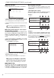
• The <E-MAIL ADDRESS> screen appears.
<E-MAIL ADDRESS>
SMTP SERVER
RECORDER ID
USER ADDRESS
1
2
3
4
5
“E-MAIL ADDRESS” is displayed only for 20 char-
acters from the beginning.
• SERVICE PORT SETTING
The port number can be set here to connect personal
computer.
Do not change the setting without sufficient knowl-
edge about the network setting.
When performing other setting except “WEB”, the
DX-PC25 software is required. Please refer to the in-
struction manual of the software.
1. Press the SET UP button
}
<SETTINGS>
}
<INITIAL SET
UP/INFORMATION>
}
<COMMUNICATION PORT
SETTINGS>
}
select “SERVICE PORT SETTING” in the
<ETHERNET> screen.
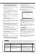
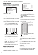
• The <SERVICE PORT SETTING> screen appears.
<SERVICE PORT SETTING>
>>
WEB •00080
USER ACCESS 53705
SUPER USER 53706
LIVE USER1 53707
LIVE USER2 53708
LIVE USER3 53709
LIVE USER4 53710
2. Turn the JOG dial to select the desired setting and turn the
SHUTTLE ring clockwise.
• The first figure of the port number reverses in color.
3. Turn the JOG dial to display the desired figure reversed in
color, and turn the SHUTTLE ring.
• The background of the selected figure turns red and flashes.
4. Turn the JOG dial to display the desired port number and
turn the SHUTTLE ring clockwise.
• The setting is confirmed and stops flashing.
When change to “WEB” setting, the “ • ” situated on
the left of the port number turns its color from green to red.
5. To change other settings repeat steps 2 ~ 4.
6. Return to the <ETHERNET> screen by turning the SHUTTLE
ring and press the SET UP button to exit if no changes are made.
7. When settings are changed, press the SET UP button for 1
second, the unit will reset and turn back on automatically.
• ALARM NOTIFICATION SETTING
Setting the transmission of warning signals or other sig-
nals when status changes such as a activation of a rear
terminal or when initiating the recording.
The specific software is required. Please refer to
the instruction manual of the software.
Issuing of reports to broadcast addresses is not
supported.
1. Press the SET UP button
}
<SETTINGS>
}
<INITIAL SET
UP/INFORMATION>
}
<COMMUNICATION PORT
SETTING>
}
select “ALARM NOTIFICATION SETTING” in
the <ETHERNET> screen.
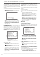
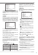
• The <ALARM NOTIFICATION SETTING> screen appears.
<ALARM NOTIFICATION SETTING>
NO IP ADDRESS TARGET OWN
>>
1 000.000.000.000•55111 01111
2 000.000.000.000•55111 01112
3 000.000.000.000•55111 01113
4 000.000.000.000•55111 01114
5 000.000.000.000•55111 01115
WARNING OFF
ALARM SENS OFF
REC MODE OFF
RETRY TIME 10S
2. (Select the IP ADDRESS number of connected PC, the
port setting number, etc. • • • )
Turn the JOG dial to select the desired setting number and
turn the SHUTTLE ring clockwise.
• The left most figure of the port number reverses in color.
3. Turn the JOG dial to display the desired figure of numbers
of IP ADDRESS, TARGET PORT and OWN PORT reversed
in color and turn the SHUTTLE ring.
• The background of the desired figure turns red and flashes.
4. Turn the JOG dial to display the desired number and turn
the SHUTTLE ring clockwise.
• The setting is confirmed and stops flashing.
When TARGET PORT number is set to 00000 -
01023, the “ • ” situated on the left of the value turns red
from green, and in case of 01024 - 49151 turns yellow.
5. To change other setting number repeat steps 2 ~ 4.
6. (Enter the IP address of the PC which is to recive the alarm
notification • • • )
Turn the JOG dial to select the desired setting and turn the
SHUTTLE ring clockwise.
• The background of the setting turns red and flashes.
Setting of “WARNING” ( default : “OFF” )
“ON” : Transmits warning message to connected PC.
E-mail is sent to address displayed on “USER AD-
DRESS” of the <E-MAIL ADDRESS> screen.
“OFF” : Does not transmit.
<INITIAL SET UP/INFORMATION> (continued)