User Guide FC810 microATX Motherboard www.trimond.
Document History 1.0 First release April 99 Trademarks mentioned within this document are the properties of their respective owners. Details available on request. Information contained in this document is subject to change without notice and does not represent a commitment on the part of Mitsubishi Electric Motherboard Division.
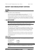
This product contains a lithium battery. Do not use a metal or other conductive implement to remove the battery. If a short-circuit is made between its positive and negative terminals the battery may explode. Replace a discharged battery with one of the same type; another type may explode or ignite. Follow the instructions contained in section 3 of this document to replace the battery.
This product complies with the American Safety Standard UL1950.
1 Overview 8 Motherboard Features...................................................................................................................... 9 Configuration Options ................................................................................................................... 10 Build-time ................................................................................................................................
Additional I/O................................................................................................................................ 21 IDE Disk Controller................................................................................................................. 21 Universal Serial Bus (USB) ..................................................................................................... 21 Security...........................................
USB Ports 0 and 1.................................................................................................................... 38 Serial Port 1 (9 way D-type) .................................................................................................... 38 VGA (15 way D-type) ............................................................................................................. 39 Parallel Port (25 way D-type) ................................
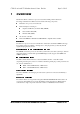
FC810 microATX is a Celeron™ processor-based microATX profile motherboard. The design of FC810 microATX is based around the following components. Intel Celeron™ processor in Socket 370 Intel 810 Chipset consisting of :- Graphics and Memory Controller Hub (GMCH) I/O Controller Hub (ICH) Firmware Hub (FWH) AC’97 audio controller Intel 82559 IEE802.
Form factor microATX, 9.6" wide x 7.8" deep. ATX 2.01 compliant. Processor Socket370 with the VRM8.2 regulator on motherboard. Accepts 66/100Mhz Celeron™ processors Core logic Intel 810 Cache L2 cache included on processor module. Memory – RAM Memory sockets accept 168 pin un-buffered PC100 SDRAM modules.
The following items can be configured at build-time and cannot be modified by the user. Integrated Graphics Controller 4Mb Display Cache Ethernet controller/ connector MIDI / Game Port features AC’97 Audio Hardware monitoring functions (Super I/O) Please contact Mitsubishi Electric Motherboard Division to determine available configurations. The user can configure the following items.
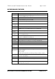
CPU SOCKET 370 IC10 SYSTEM BUS 4MB DISPLAY CACHE IC 14 /16 GMCH IC15 DIMM MODULES MM 1,2 FWH IC21 HUB LINK AUDIO AC'97 IC 3 ICH IC13 IDE PL22 / 16 SUPER I/O IC23 FLOPPY PL21 SERIAL PL2 LPC BUS USB PL4 PCI CONN 4 PL13 RJ45 PL4 KEYBOARD MOUSE PL1 PARALLEL PL2 PCI BUS GAME/MIDI PL3 82559 LAN IC11 PCI CONN 1 PL10 PCI CONN 2 PL11 MITSUBISHI ELECTRIC MOTHERBOARD DIVISION PCI CONN 3 PL12 PAGE 11 OF 45
Warning Static electricity can cause permanent damage to electronic components. You should be aware of this risk, and take precautions against the discharge of static electricity.
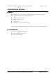
1 Chasis Intrusion Header PL17 15 Graphics and memory controller hub (GMCH) C RJ45 2 Hard Switch PSU jumper PL18 16 4MB display cache D USB (Dual) 3 Front panel 17 PCI expansion slots PL10,11,12,13 E Serial Port 1 4 Floppy disk PL21 18 Debug connector PL15 F VGA 5 Main power PL19 19 System fan power PL9 G Parallel 6 Primary IDE Controller PL22 20 CPU fan power PL8 H Line output 7 Secondary IDE Controller PL16 21 Processor
Caution Care must be taken in the purchase of upgrade parts to ensure both compatibility with the system and the compliance with appropriate approvals and certification, e.g. CE marking within Europe. Using non-approved parts may invalidate your warranty and system approvals.
! Do not use excessive force. If the module will not fit easily, remove it and start again. The DIMM is inserted vertically and held in place by the clips at each end. " ! Do not use excessive force. If the module will not come free easily, check that the holding clips are clear of the module ends. Press the tabs on both of the socket’s end clips at the same time. This releases the DIMM and lifts it partly out of the socket.
# $ 1. Hold the processor by the edges – avoid touching the pins on the underside The processor and socket and keyed to ensure the processor is installed in the correct orientation. It will only fit into the socket one way. 2. When the processor is securely in place close the clip on the socket. Do not use excessive force. 3. Refit the heatsink/ fan making sure it is correctly and fully seated on the processor.
The FC810 microATX motherboard accepts the following Celeron™ processors operating at a bus speed of 66 or 100MHz. 266 4.0 66 300 4.5 66 333 5.0 66 366 5.5 66 400 6.0 66 433 6.5 66 466 7.0 66 500 5.0 100 550 5.5 100 600 6.0 100 The processor core voltages are generated by switched-mode regulators on the motherboard to the Intel VRM8.2 specification.
PCI Bus – supports Rev 2.2 spec and 4/ 6 (optional) master devices Dual UltraDMA33/ 66 (optional) IDE controller Dual USB controller (12Mbps or 1.
!% The BIOS is contained in a flash ROM device – Firmware Hub (FWH) soldered directly to the motherboard and includes the code listed below. The motherboard will automatically perform a BIOS recovery operation if it detects a valid recovery disk during the boot sequence. The BIOS ROM is accessed as a single linear region in the memory space from 4GB-128kB (0FFFE0000 0FFFFFFFFh) and copied at the top of ISA memory (0E0000 - 0FFFFFh).
The following audio connectors are supported. Rear 3.5mm jack microphone input with phantom power Rear 3.5mm jack LINE in Rear 3.
+ + This is EPP 1.9 and IEE1284 (ECP) compliant and is compatible with a standard (output only) PC parallel port as well as a bi-directional (PS/2 style) parallel port. There is a 25-way D-type connector on the rear panel. ! * Two UltraDMA33/ (66 - ICH1) IDE ports are provided with the controller integrated into the ICH. This allows for a maximum of four drives to be connected - two to each port.
$ , The motherboard supports an ACPI-compliant standby switch for use with a soft-switch power supply. The action of the switch is under a combination of hardware and software control and is summarised in the table below. The motherboard will power off regardless of the state of software if the switch is held down for more than 4 seconds.
There are three main elements to the optional system management hardware. MAX1617 Thermal Monitor PC87366 Super I/O Processor thermal diode ADCs -./.( A precise digital thermometer that reports both the CPU temperature and the temperature of itself – system temperature. It is accessed via the ICH SMbus interface. + 0(1// The National Semiconductor PC87366 provides the system monitor functions as described below.
+ ! ! " # INTA# Slots INTB# Slots INTC# Slots INTD# LAN & Slots + ! , # $ % $ $ % " $ " 0 0 0 Host-hub interface Bridge/ DRAM controller 0 1 0 GMCH internal graphics device 0 4 0 20 82559 LAN Controller 0 9 0 25 Slot 4 0 11 0 27 Slot 3 0 13 0 29 Slot 2 0 15 0 31 Slot 1 0 30 0 Hub in
+ ! & % 0 0 PCI slot 1 1 0 PCI slot 2 2 0 PCI slot 3 3 0 PCI slot 4 4 0 82559 LAN Controller " # " Note that the arbiter implements a round robin scheme and thus no request level has fixed priority over another.
BIOS (pronounced “bye-oss”) stands for ‘basic input/output system’. The BIOS mediates between the computer’s hardware – the processor, memory, and so on – and its software – the operating system and your programs. The BIOS program is kept in permanent, read-only memory or ROM (although if necessary it can be upgraded by an authorised maintainer). BIOS Setup is a helpful utility that forms part of the BIOS program.
' Minus (-) or F5 Select the previous value for the current field. Enter Make a selection from the menu bar or enter a sub-menu. Home or End Move the cursor to the top or bottom of the current menu. Page up or Page down Move the cursor to the next or previous page of the current menu. F9 Restore the default settings for the fields on the current menu. F10 Save the changes you’ve made and exit from BIOS Setup.
" +% # Whenever a recoverable (non-terminal) error occurs during POST, the BIOS displays an error message describing the problem (the most usual are described below). After some messages, you may be prompted to Press to resume, to enter Setup or just Press to enter Setup.
Operating system not found An operating system cannot be located either on a system diskette or on a hard disk. Start BIOS Setup and check that the diskette and/or hard disk drives are specified correctly. Parity check 1 xxxx or Parity check 2 xxxx Parity error found on the system (1) or I/O (2) bus. The BIOS attempts to locate and display the address xxxx. If it cannot locate the address, it displays “????”.
The BIOS also issues Port 80h codes that can be displayed using a suitable diagnostic card. The codes can be used to determine the failure.
( ' 36h Warm start shut down 37h Reinitialise the chipset (MB only) 38h Shadow system BIOS ROM 39h Reinitialise the cache (MB only) 3Ah Autosize cache 3Ch Advanced configuration of chipset registers 3Dh Load alternate registers with CMOS values 42h Initialise interrupt vectors 44h Initialise BIOS interrupts 45h POST device initialisation 46h Check ROM copyright notice 48h Check video configuration against CMOS 49h Initialise
( ' 70h Display error messages 72h Check for configuration errors 74h Test real- time clock 76h Check for keyboard errors 77h SMBus init devices 78h Initialise system monitor and check for intrusion 79h PCI audio init 7Ah Test for key lock on 7Ch Set up hardware interrupt vectors 7Eh Initialise coprocessor if present 80h Disable onboard Super I/ O ports and IRQs 81h Late POST device initialisation 82h Detect an
( ' A0h Set time of day A2h Check key lock A4h Initialise typematic rate A8h Erase F2 prompt AAh Scan for F2 key stroke ACh Enter SETUP AEh Clear IN POST flag B0h Check for errors B1h ROMPilot unload B2h POST done - prepare to boot operating system B4h One short beep before boot B5h Terminate QuietBoot B6h Check password (optional) B7h ACPI initialisation B8h Clear global descriptor table B9h Clean up all graphics BAh
( ' E6h Checksum BIOS ROM E7h Go to BIOS E8h Initialise Multi Processor E9h Set Huge Segment EAh Initialilze OEM special code EBh Initialise PIC and DMA ECh Initialise Memory type EDh Initialise Memory size EEh Shadow Boot Block EFh System memory test F0h Initialise interrupt vectors F1h Initialise Run Time Clock F2h Initialise video F3h Initialise beeper F4h Initialise boot F5h Clear Huge segment F6h Boot to Mini DO
The following codes are produced during the BIOS recovery sequence.
! " The motherboard power requirements are heavily dependent on system configuration and the software being used. The table below can be used as a guide to the likely power supply requirements. They are measured using a 400MHz Intel Celeron Processor and 2 memory modules running stress test software designed to yield worst case results. They should not, however, be regarded as maximum values. ") *+, *+, *-.
# ) + 34 !5 (Installation guide references A and B) 2 1 " CLK I/O Data clock 2 VCC O +5V Power 3 GND - Signal ground 4 NC - No connect 5 DATA I/O Serial data 6 NC - No connect 6 5 "789 (Installation guide reference C) 2 " 1 TX+ O Transmit Data + 2 TX- O Transmit Data - 3 RX+ I Receive Data + 4 NC - Not co
+ : . (Installation guide reference D) 4 1 USB Port 0 USB Port 1 1 4 2 1 " VCC O +5V Power 2 DATA- I/O Differential Serial Data - 3 DATA+ I/O Differential Serial Data + 4 GND - Signal ground + .
;2 .
+ + 49 $ (Installation guide reference G) 13 1 25 14 $ ! $ 1 STB# STB# 2 DATA0 DATA0 I/O 3 DATA1 DATA1 I/O 4 DATA2 DATA2 I/O 5 DATA3 DATA3 I/O 6 DATA4 DATA4 I/O 7 DATA5 DATA5 I/O 8 DATA6 DATA6 I/O 9 DATA7 DATA7 I/O 10 ACK# ACK# I 11 BUSY BUSY I 12 PE PE I 13 SLCT SLCT I 14 AFD# AFD# O 15 ERR# ERR# I 16 INIT# INIT# O 17 SLIN# SLIN# O 18 GND GND - 1
6 ! % 1<9 = * (Installation guide references I and H) 2 " Sleeve GND Tip Left channel Ring Right channel , ! 1<9 = * (Installation guide reference J) 2 " Sleeve GND Tip Mono input Ring Electret bias voltage ! !37 * .
, ! $ , 4 $ :<.> , (Installation guide references 1) 2 " 1 Switch input. Switch should be open when chassis is closed. 2 GND + ! * 8: $ $ :<.
$ :<.> , (Installation guide reference 3) 2 " 1 Power switch.
* 18 $ $ :<.
! 6!5 8 $ # +! , (Installation guide reference 23) 2 1 " LEFT I Left audio input 2 GND - Signal ground 3 GND - Signal ground 4 RIGHT I Right audio input ! 8 $ # +! , (Installation guide reference 24) 2 1 " LEFT I Left audio input 2 GND - Signal ground 3 GND - Signal ground 4 RIGHT I Right audio input !