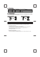
FX-485ADP COMMUNICATION ADAPTER FX0N-485ADPCOMMUNICATION ADAPTER USER'S GUIDE JY992D53201C This manual contains text, diagrams and explanations which will guide the reader in the correct installation and operation of the FX and FX0N, 485 communication adapters. It should be read and understood before attempting to install or use these units. Further information can be found in the FX PROGRAMMING MANUAL, FX and FX0/FX0N series hardware manuals.
INTRODUCTION 1 The adapter for FX-485ADP RS485 or the adapter for FX0N-485ADP RS485 (both called 485ADP hereinafter) is designed to link the data between PC and computer by using 485PC-IF. (1)Data exchange by request from computer Specified data can be exchanged by sending a request command from the computer to the PC. Except for few functions (global function, on-demand function), the program for data link is not needed at the PC side.
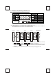
1.2 System configuration The system configuration of computer and PC is either 1 : 1 or 1 : n, and for communication with the computer, the RS-485 or RS-422 is used. (1) Computer and PC by 1 : 1 configuration , , , , , , , , , , , , , , , , , , FX,FX2C series PC , , , , , , Computer 485PC-IF 485ADP Station No.0 : : : : RS-232C interface RS-485 interface RS-232C cable RS-422 or RS-485 cable Max.
1.3 Applicable PCs For setting up the system, the 485ADP can be connected to the following PCs. PC version Remarks PC series FX0N-485ADP FX0N Ver. 1.20 or later Exclusive protocol format 1 and format 4 are supported. Ver. 3.30 or later Exclusive protocol format 1 and format 4 are supported. FX-485ADP FX , FX2C As for exclusive protocol formats (1, 4) , see the 485PC-IF manual. 1.
2.
2.
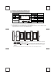
2.3 Terminating resistances The terminating resistances are resistances connected between terminals SDA and SDB, and between terminals RDA and RDB at both end stations of the circuit (or the interface when an interface such as 485PC-IF is used at both end stations), when connecting with the RS-485 or RS-422 circuit. For connection examples, see section 2.1 and 2.2.
SPECIFICATIONS 3 Environmental specifications Operating ambient temperature 0 to 55°C, storage temperature -20 to 70°C Humidity no condensation 35 to 85% RH (No condensation) Conforming to JIS C 0911. 10 to 55 Hz, 0.5 mm (max. 2G), 2 hr each in 3 axes; however, 0.5G Vibration resistance when mounting DIN rail. Shock resistance Conforming to JIS C 0912. 10G, 3 times each in 3 axes Noise immunity Noise voltage 1000V p-p, noise width 1µsec, period 30 to 100 Hz, by noise simulator.
COMMAND AND DEVICE RANGE 4 4.1 Computer commands Command Objective Number of processing points done by one communication device symbol FX, FX2C FX0N Function Symbol ASCII code BR WR BW WW BT WT 42H,52H To read out on/off state of bit device in batch in the unit of 1 point. To read out on/off state of bit device in batch in the unit of 57H,52H 16 points. To read out numerical data stored in word device in batch in the unit of 1 point.
5 DIAGNOSTICS In case of trouble, check the following points, and remedy according to the troubleshooting guide in the 485PCIF manual. (1) Power LED Lit : The extension cable is normally connected to the PC. Otherwise : The extension cable is not connected correctly, or external 24 V DC power supply is not functioning correctly. Check and connect correctly. (2) As for SD LED, RD LED, check and remedy according to the troubleshooting guide in the 485PC-IF manual.
START UP PROCEDURE 6 Prior to start of operation, follow the procedure below. As for detail of procedure, see the 485PC-IF manual.
Guidelines for the safety of the user and protection of the FX-485ADP, FX0N -485ADP communication adapter ● This manual has been written to be used by trained and competent personnel. This is defined by the European directives for machinery, low voltage and EMC. ● If in doubt at any stage during the installation of the FX-485ADP, FX0N-485ADP always consult a professional electical engineer who is qualified and trained to the local and national standards.