Analog-Digital Converter Module U User's Manual Analog-Digital Converter Module User's Manual Analog-Digital Converter Module User's Manual MODEL Q-A/D-U-S-E MODEL CODE 13JR03 SH(NA)-080055-C(0106)MEE HEAD OFFICE : MITSUBISHI DENKI BLDG MARUNOUCHI TOKYO 100-8310 TELEX : J24532 CABLE MELCO TOKYO NAGOYA WORKS : 1-14 , YADA-MINAMI 5 , HIGASHI-KU, NAGOYA , JAPAN When exported from Japan, this manual does not require application to the Ministry of Economy, Trade and Industry for service transaction pe
• SAFETY PRECAUTIONS • (Always read these instructions before using this equipment.) Before using this product, please read this manual and the relevant manuals introduced in this manual carefully and pay full attention to safety to handle the product correctly. The instructions given in this manual are concerned with this product. For the safety instructions of the PLC system, please read the user's manual for the CPU module to use.
[INSTALLATION PRECAUTIONS] ! CAUTION • Use the PLC in an environment that meets the general specifications contained in the user's manual of the CPU module to use. Using this PLC in an environment outside the range of the general specifications may cause electric shock, fire, malfunction, and damage to or deterioration of the product.
[STARTING AND MAINTENANCE PRECAUTIONS] ! CAUTION • Do not disassemble or modify the modules. Doing so could cause failure, malfunction injury or fire. • Switch all phases of the external power supply off when mounting or removing the module. Not doing so may cause failure or malfunction of the module. The system that uses the QnPHCPU allows you to change a module online. Note that there are restrictions on the modules that can be changed online and each module has a predetermined changing procedure.
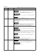
REVISIONS The manual number is given on the bottom left of the back cover. Print Date Dec., 1999 Oct., 2000 Manual Number Revision SH (NA)-080055-A First printing SH (NA)-080055-B Add the contents of the function version B. Correction About the Generic Terms and Abbreviations, Section 2.1, Section 3.1.3, 3.4.1, Section 4.3, 4.4.2, Section 5.2.1, 5.2.2, 5.3.3, 5.6.1 Partial addition Section 1.1, Section 3.1.1, 3.1.2, 3.2, 3.3.1, 3.3.2, Section 4.5, Section 7.2.3, 7.2.4 Addition Section 1.2, Section 2.
Print Date Feb., 2003 Manual Number SH (NA)-080055-F Revision Correction SAFETY PRECAUTIONS, Section 1.2, Section 2.1, Section 3.4.1 to 3.4.3, 3.4.15, Section 4.5, Section 5.1, 5.2.1, 5.2.2, 5.3.2, 5.6.1 to 5.6.3, Section 7.3.1, 7.3.3 to 7.3.6, Appendix 1.1, Appendix 1.2, Appendix 2.2, Appendix 2.3 Addition Section 5.6.4, 5.6.5 May, 2003 SH (NA)-080055-G Correction Section 2.2, Section 3.4.1, 3.4.2, 3.4.3, 3.4.14, 3.4.15, Section 4.5, 4.6, Section 5.3.
INTRODUCTION Thank you for purchasing the MELSEC-Q series PLC. Before using the equipment, please read this manual carefully to develop full familiarity with the functions and performance of the Q series PLC you have purchased, so as to ensure correct use. Please forward a copy of this manual to the end user. CONTENTS SAFETY PRECAUTIONS..............................................................................................................................A- 1 REVISIONS .................................
3.4.12 Maximum and minimum values storage area (buffer memory addresses 30 to 45: Un\G30 to Un\G45) ............................................................ 3-24 3.4.13 Mode switching setting (buffer memory addresses 158, 159: Un\G158, Un\G159).................... 3-25 3.4.14 Pass data classification setting (buffer memory addresses 200: Un\G200) (Q64AD only)......... 3-25 3.4.
7.3.1 When industrial shipment setting is used and initial setting was made with GX Configurator-AD ........................................................................................................................................................ 7 - 3 7.3.2 When industrial shipment setting is used and initial setting was made with sequence program. 7 - 8 7.3.3 When user range setting is used and initial setting was made with GX Configurator-AD (other system is available) .............................
Conformation to the EMC Directive and Low Voltage Instruction For details on making Mitsubishi PLC conform to the EMC directive and low voltage instruction when installing it in your product, please see Chapter 3, "EMC Directive and Low Voltage Instruction" of the User's Manual (Hardware) of the PLC CPU to use. The CE logo is printed on the rating plate on the main body of the PLC that conforms to the EMC directive and low voltage instruction.
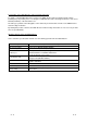
Product Structure The product structure of this product is given in the table below.
1 OVERVIEW MELSEC-Q 1 OVERVIEW This User's Manual describes the specifications, handling and programming methods for the Q64AD analog-digital converter module (hereinafter referred to as the Q64AD), Q68ADV analog-digital converter module (hereinafter referred to as the Q68ADV), and Q68ADI analog-digital converter module (hereinafter referred to as the Q68ADI), which are used in conjunction with MELSEC-Q Series CPUs.
1 OVERVIEW MELSEC-Q 1.2 Functions Added to Function Version B and Later 1 (1) Functions added to function version B The functions added by the function version B A/D converter module are listed below. Item Multiple PLC system compatibility Function overview Compatible with a multiple PLC system. A PLC CPU of function version B or later are required. The resolution mode can be changed according to the application, and digital-value resolution settings of 1/4000, 1/12000 or 1/16000 can be selected.
2 SYSTEM CONFIGURATION MELSEC-Q 2 SYSTEM CONFIGURATION 2.1 Applicable Systems This section describes the system configuration for the A/D converter module. (1) Applicable module and the number of modules that can be installed The following are the CPU module and network module (for remote I/O stations) in which the A/D converter module can be installed and the number of modules that can be installed.
2 SYSTEM CONFIGURATION MELSEC-Q (4) Compatibility with online module change To make an online module change, use the module of function version C or later. POINT The products of function version C include the functions of the products of function versions A and B. 2 (5) Software packages supported Correspondence between systems which use A/D converter modules and software packages are as shown below. The GX Developer is necessary when using a A/D converter module.
2 SYSTEM CONFIGURATION MELSEC-Q 2.2 How to Check the Function Version and Software Version This section describes how to check the function version of the A/D converter module and the GX Configurator-AD software version. (1) How to check the function version of the A/D converter module (a) To check the version using the "SERIAL column of the rating plate" located on the side of the module Function version 80M1 IND. CONT. EQ. (b) To check the version using the GX Developer See Section 8.2.
2 SYSTEM CONFIGURATION MELSEC-Q REMARK The version indication for the GX Configurator-AD has been changed as shown below from the SW0D5C-QADU-E 50F upgrade product. Previous product Upgrade and subsequent versions SW0D5C-QADU-E 50F GX Configurator-AD Version 1.
3 SPECIFICATIONS MELSEC-Q 3 SPECIFICATIONS 3.1 Performance Specifications 3.1.1 Performance specifications list Table 3.1 shows the performance specifications of the A/D converter modules. Table 3.
3 SPECIFICATIONS MELSEC-Q Model name Q64AD Item Q68ADV Q68ADI s/channel 80 (When there is temperature drift, the time calculated by adding 160 Conversion speed s will be used regardless of the number of channels used) Absolute maximum input Voltage : ± 15 V 2 E PROM write count Max.
3 SPECIFICATIONS MELSEC-Q (1) Voltage input characteristic (a) Voltage input characteristic in normal resolution mode Figure 3.1 shows a graph of the voltage input characteristic in normal resolution mode.
3 SPECIFICATIONS MELSEC-Q (b) Voltage input characteristic in high resolution mode Figure 3.2 shows a graph of the voltage input characteristic in high resolution mode.
3 SPECIFICATIONS MELSEC-Q POINT (1) Set within the analog input range and digital output range for each input range. If these ranges are exceeded, the maximum resolution and accuracy may not fall within the performance specifications. (Avoid using the dotted line area shown in Figures 3.1 and 3.2.) (2) Do not input an analog input voltage of more than ± 15 V. The input elements may be damaged. (3) Set the offset/gain values for the user setting range the following conditions are satisfied.
3 SPECIFICATIONS MELSEC-Q (2) Current input characteristic (a) Current input characteristic in normal resolution mode Figure 3.3 shows a graph of the current input characteristic in normal resolution mode.
3 SPECIFICATIONS MELSEC-Q (b) Current input characteristic in high resolution mode Figure 3.4 shows a graph of the current input characteristic in high resolution mode.
3 SPECIFICATIONS MELSEC-Q POINT (1) Set within the analog input range and digital output range for each input range. If these ranges are exceeded, the maximum resolution and accuracy may not fall within the performance specifications. (Avoid using the dotted line area shown in Figures 3.3 and 3.4.) (2) Do not input an analog input current of more than ± 30 mA. A breakdown may result due to overheating. (3) Set the offset/gain values for the user setting range the following conditions are satisfied.
3 SPECIFICATIONS MELSEC-Q 3.1.3 Accuracy Accuracy is represented with respect to the maximum digital output value. Accuracy does not change and remains within the range listed in the performance specification even if the input characteristic is changed by changing offset/gain settings, input range and resolution mode. Figure 3.5 shows the range of fluctuation in accuracy when a -10 to 10V range is selected and in normal resolution mode. Accuracy is ± 0.
3 SPECIFICATIONS MELSEC-Q 3.2 Function List Table 3.2 shows the function list of the A/D converter modules. Table 3.2 Function list Item Function Reference section (1) Specifies whether to enable or disable the A/D conversion for each channel. A/D conversion enable/ (2) By disabling the conversion for the channels that are not used, the disable setting sampling time can be shortened.
3 SPECIFICATIONS MELSEC-Q (a) When averaging processing is specified for the set amount of time 1) The number of processing repetitions within the set time differs according to the number of channels used (number of channels for which A/D conversion is enabled) and whether or not temperature-drift compensation is used.
3 SPECIFICATIONS MELSEC-Q 3.2.2 Maximum and minimum values hold function (1) The maximum and minimum digital output values for each channel are stored in buffer memory addresses 30 to 45 (Un\G30 to Un\G45). (2) When the operating condition setting completed flag (X09) turns OFF, the values are cleared to 0 and new maximum and minimum values are stored when conversion begins.
3 SPECIFICATIONS MELSEC-Q 3.3.2 Details of I/O signals I/O signals for the A/D converter modules are explained in detail below. (1) Input signals Device No. Signal Name Description (1) When the PLC CPU is powered on or reset, this signal turns on once the preparation for A/D conversion has been completed, and A/D conversion X0 Module READY processing is then performed. (2) When the Module READY signal is off, A/D conversion processing is not performed.
3 SPECIFICATIONS Device No. MELSEC-Q Signal Name Description [In offset/gain setting mode] (1) This is used as an interlock condition for setting the offset/gain request (YA) to ON/OFF when registering the value after adjustment of the offset/gain settings have been completed. (2) See Section 4.6 regarding the offset/gain settings.
3 SPECIFICATIONS Device No. MELSEC-Q Signal name Description (1) This is used as an interlock condition for setting the channel change request (YB) to ON/OFF when changing the channel for which the offset/gain settings are to be performed. (2) See Section 4.6 regarding the offset/gain settings.
3 SPECIFICATIONS MELSEC-Q (2) Output signals Device No. Signal name Description (1) This turns ON when A/D conversion is enabled/disabled, or when averaging Operating Y9 condition setting request processing specification, the settings for the average time or number of times (when averaging processing is specified) is enabled. (2) See the X9 column for ON/OFF timing.
3 SPECIFICATIONS MELSEC-Q 3.4 Buffer Memory The detailed explanation of the buffer memory in Section 3.4.4 and later is based on the 8-channel analog input (CH. 1 to CH. 8) Q68ADV/Q68ADI. 3.4.1 Buffer memory assignment (Q64AD) This section describes the assignment of the Q64AD buffer memory. Table 3.
3 SPECIFICATIONS MELSEC-Q 3.4.2 Buffer memory assignment (Q68ADV) This section describes the assignment of the Q68ADV buffer memory. Table 3.
3 SPECIFICATIONS MELSEC-Q 3.4.3 Buffer memory assignment (Q68ADI) This section describes the assignment of the Q68ADI buffer memory. Table 3.
3 SPECIFICATIONS MELSEC-Q 3.4.4 A/D conversion enable/disable setting (buffer memory address 0: Un\G0) (1) Sets whether the output of an A/D conversion value is enabled or disabled for each channel. (2) It is necessary to set the operating condition setting request (Y9) to ON/OFF in order to enable the A/D conversion enable/disable setting. (See Section 3.2.2.) (3) By default, A/D conversion is enabled for all channels. (4) In the case of the Q64AD module, b4 to b7 (CH5 to CH8) become invalid.
3 SPECIFICATIONS MELSEC-Q 3.4.6 Averaging processing setting (buffer memory address 9: Un\G9) (1) When selecting sampling processing or averaging processing, write the setting to buffer memory address 9 (Un\G9). (2) When averaging processing is selected, select average time or average number of times. (3) By default, sampling processing is set for all channels. (4) In the case of the Q64AD module, b4 to b7 and b12 to b15 (CH5 to CH8) are invalid.
3 SPECIFICATIONS MELSEC-Q 3.4.7 A/D conversion completed flag (buffer memory address 10: Un\G10) (1) When A/D conversion for the channels enabled for conversion is complete, the A/D conversion completed flag is set to 1. The A/D conversion completed flag (XE) is set to ON when the conversion for all A/D conversion enabled channels is complete. (2) When the operating condition setting request (Y9) is set to ON, the flag returns to the default setting of 0 and changes to 1 when A/D conversion is complete.
3 SPECIFICATIONS MELSEC-Q 3.4.9 Write data error codes (buffer memory address 19: Un\G19) (1) The error codes generated by the A/D converter modules are stored here. (2) See Section 8.1 for the details of the error codes. 3.4.10 Setting ranges (buffer memory addresses 20, 21: Un\G20, Un\G21) (1) These areas are used to confirm the setting ranges of the A/D converter module.
3 SPECIFICATIONS MELSEC-Q 3.4.11 Offset/gain setting mode (buffer memory addresses 22, 23: Un\G22, Un\G23) (1) Specifies the channel to be adjusted for the offset/gain settings. (2) The channel for which the offset is to be adjusted is specified in buffer memory address 22 (Un\G22) and the channel for which the gain is to be adjusted is specified in buffer memory address 23 (Un\G23).
3 SPECIFICATIONS MELSEC-Q 3.4.13 Mode switching setting (buffer memory addresses 158, 159: Un\G158, Un\G159) (1) Set the values of the mode to which you want to switch. (2) After setting the values, turning the operation condition setting request (Y9) from OFF to ON switches to that mode. (3) When mode switching is performed, this area is cleared to zero and the operating condition setting completed flag (X9) turns OFF.
3 SPECIFICATIONS MELSEC-Q 3.4.15 Industrial shipment settings and user range settings offset/gain values (buffer memory addresses 202 to 233: Un\G202 to Un\G233) (1) Areas used to restore the user range settings offset/gain values when online module change is made. Refer to chapter 7 for details of online module change. (2) When the offset/gain values of the user range setting are restored, the used data are stored.
4 SETUP AND PROCEDURES BEFORE OPERATION MELSEC-Q 4 SETUP AND PROCEDURES BEFORE OPERATION 4.1 Handling Precautions (1) Do not drop the module or subject it to heavy impact. (2) Do not remove the PCB of the module from its case. Doing so may cause the module to fail. (3) Be careful not to let foreign particles such as swarf or wire chips enter the module. They may cause a fire, mechanical failure or malfunction.
4 SETUP AND PROCEDURES BEFORE OPERATION MELSEC-Q 4.2 Setup and Procedures before Operation Start Module mounting Mount the A/D conversion module in the specified slot. Wiring Wire external devices to the A/D conversion module. Intelligent function module switch settings Perform settings using GX Developer (see Section 4.5). 4 Use industrial shipment settings.
4 SETUP AND PROCEDURES BEFORE OPERATION MELSEC-Q 4.3 Part Identification Nomenclature The name of each part of the A/D converter module is listed below. Q64AD 1) Q68ADV 1) Q64AD 1) Q68ADV Q68ADI RUN RUN RUN ERROR ERROR ERROR 2) 2) V+ V- C H 1 I+ SLD V+ V- C H 2 I+ SLD V+ V- C H 3 I+ SLD V+ V- C H 4 I+ SLD A.G.
4 SETUP AND PROCEDURES BEFORE OPERATION Signal name Terminal number Q64AD 1 2 3 V+ CH1 V– I+ SLD 5 V+ 7 CH2 V– I+ 8 SLD 9 V+ 10 V– 11 CH3 I+ 12 SLD 13 V+ 14 V– 15 16 4-4 Q68ADV 4 6 MELSEC-Q CH4 I+ SLD Q68ADI V+ CH1 V– V+ CH2 V– V+ CH3 V– V+ CH4 V– V+ CH5 V– V+ CH6 V– V+ CH7 V– V+ CH8 V– 17 A.G.
4 SETUP AND PROCEDURES BEFORE OPERATION MELSEC-Q 4.4 Wiring The wiring precautions and examples of module connection are provided below. 4.4.1 Wiring precautions In order to optimize the functions of the A/D converter module and ensure system reliability, external wiring that is protected from noise is required.
4 SETUP AND PROCEDURES BEFORE OPERATION MELSEC-Q 4.4.2 External wiring (1) Q64AD (a) For voltage input Signal source 0 to ± 10 V 2 + 15 V 500 k V+ I+ V– 500 k SLD GND 1 Shielded (b) For current input Signal source 0 to ± 20 mA – 15 V + 15 V 2 3 500 k V+ I+ V– 250 500 k SLD GND 1 Shielded – 15 V A.G. FG 4 ANALOG GND 5 1 2 3 4 Use a twisted two core shielded wire for the power wire. Shows input resistance of Q64AD. If current input, always connect to (V +) and (I +) terminals. "A.G.
4 SETUP AND PROCEDURES BEFORE OPERATION MELSEC-Q (2) Q68ADV 2 + 15 V 500 k V+ V– 500 k A.G. GND – 15 V FG 1 Shielded 3 ANALOG GND 4 1 Use a twisted two core shielded wire for the power wire. 2 Shows input resistance of Q68ADV. 3 "A.G." terminal does not normally require wiring. However, it can be used as GND for compatible equipment ground under the following conditions. (1) When there is a difference in polarity between "A.G" and "GND for compatible equipment".
4 SETUP AND PROCEDURES BEFORE OPERATION MELSEC-Q 4.5 Switch Setting for Intelligent Function Module The settings for the intelligent function module are performed using the I/O assignment settings for GX Developer. (1) Setting item The intelligent function module switches consist of switches 1 to 5 and are set using 16 bit data. When the intelligent function module switches are not set, the default value for switches 1 to 5 is 0. Table 4.
4 SETUP AND PROCEDURES BEFORE OPERATION MELSEC-Q POINT (1) If the offset/gain setting mode is set using intelligent function module switch 4, other settings by switch 4 (settings for resolution mode and temperature drift compensation) will be ignored. (2) Setting of the offset/gain setting mode differs from function version A to function version B. (Refer to Appendix 1.3) Perform the offset/gain settings after checking the RUN LED flashes in offset/gain setting mode.
4 SETUP AND PROCEDURES BEFORE OPERATION MELSEC-Q 4.6 Offset/Gain Settings When the user range setting is used, perform the offset and gain settings according to the following procedure. When the industrial shipment setting is used, offset/gain setting is not necessary. If the utility package is installed, perform the offset/gain settings according to the procedure described in Section 5.6.2. (1) Offset/gain setting procedure Start 2) Switch to the offset/gain setting mode.
4 SETUP AND PROCEDURES BEFORE OPERATION MELSEC-Q 1 The mode switching (normal mode to offset/gain setting mode to normal mode) method is given below. • Dedicated instruction (G.OFFGAN) ............. Refer to Section 4.6 (2), (a) • Setting made to mode switching setting (buffer memory addresses 158, 159: Un\G158, Un\G159) and turning the operation condition setting request (Y9) from OFF to ON ..................................................... Refer to Section 4.
4 SETUP AND PROCEDURES BEFORE OPERATION (a) MELSEC-Q When switching the mode using the dedicated instruction (G.OFFGAN) The following program switches to the offset/gain setting mode with the dedicated instruction (G.OFFGAN), changes the channel where offset/gain setting will be made, writes the offset/gain values to the A/D converter module, and then switches to the normal mode. Switches to offset/gain setting mode Stores setting of dedicated instruction (G.OFFGAN) into D1. Dedicated instruction (G.
4 SETUP AND PROCEDURES BEFORE OPERATION (b) MELSEC-Q When switching the mode using the setting of the mode switching setting (buffer memory addresses 158, 159: Un\G158, Un\G159) and operation condition setting request (Y9) Switches to offset/gain setting mode Sets 4144H to buffer memory address 158. Sets 964H to buffer memory address 159. Turns ON operation condition setting request (Y9).
5 UTILITY PACKAGE (GX Configurator-AD) MELSEC-Q 5 UTILITY PACKAGE (GX Configurator-AD) 5.1 Utility Package Functions Table 5.1 shows an overview of the utility package functions. Table 5.1 Utility package (GX Configurator-AD) function list Item Description Reference section (1) Sets the following items that require initial setting.
5 UTILITY PACKAGE (GX Configurator-AD) MELSEC-Q 5.2 Installing and Uninstalling the Utility Package See "Method of installing the MELSOFT Series" attached with the utility package regarding the install and uninstall operation for the utility package. 5.2.
5 UTILITY PACKAGE (GX Configurator-AD) MELSEC-Q (6) About the number of parameters that can be set in GX Configurator-AD The number of parameters that can be set by the GX Configurator for an intelligent function module installed in the CPU module and in a remote I/O station of the MELSECNET/H network system is limited.
5 UTILITY PACKAGE (GX Configurator-AD) MELSEC-Q 5.2.2 Operating environment The operating environment of the personal computer where the GX Configurator-AD is used is explained. Item Peripheral devices Installation (Add-in) destination 1 ® Computer main unit Hard disk 2 Add-in to GX Developer Version 4 (English version) or later Personal computer on which Windows operates. CPU Refer to the following table "Used operating system and performance required for Required memory personal computer".
5 UTILITY PACKAGE (GX Configurator-AD) MELSEC-Q 5.3 Explanation of Utility Package Operation 5.3.1 How to perform common utility package operations (1) Available control keys Special keys that can be used during operation of the utility package and their applications are shown in the table below. Name of key Esc Application Cancels a newly entered value when entering data in a cell. Closes the window. Tab Ctrl Moves between controls in the window.
5 UTILITY PACKAGE (GX Configurator-AD) MELSEC-Q (2) Data to be created with the utility package The data and files shown below that are created with the utility package are also processed using GX Developer operation. Figure 5.1 shows which operation processes which data or file. (a) This data is created with the automatic refresh setting, and stored in the intelligent function module parameter file of the project to be created using GX Developer.
5 UTILITY PACKAGE (GX Configurator-AD) MELSEC-Q (a) A text file is created by performing the initial setting or automatic refresh setting, or selecting text file creation in the monitor/test screen. The text files can be utilized to create user documents. GX Developer/ GX Configurator-AD Disk Project Project 1) A 2) A Personal computer B QCPU 3) Q25HCPU MODE. RUN. ERR. USER. BAT. BOOT. A : Indicates an intelligent function module parameter.
5 UTILITY PACKAGE (GX Configurator-AD) MELSEC-Q 5.3.2 Operation overview GX Developer screen [Tools] – [Intelligent function utility] – [Start] Intilligent function module parameter setting module select screen Enter "Start I/O No.", then select "Package name" and "Module model name". See Section 5.3.3 1) Initial setting Initial setting screen Auto refresh Automatic refresh settings screen See Section 5.5 See Section 5.
5 UTILITY PACKAGE (GX Configurator-AD) MELSEC-Q 1) [Online] – [Monitor/test] Select monitor/test module screen Enter "Start I/O No.", then select "Package name" and "Module model name". Monitor/test screen See Section 5.
5 UTILITY PACKAGE (GX Configurator-AD) MELSEC-Q 5.3.3 Starting the intelligent function module utility [Purpose of setting] Start the intelligent function module utility from GX Developer, and display the module selection screen for the intelligent function module utility parameter setting. The screens for performing initial setting, automatic refresh setting and monitor/test module selection (selecting the module for which monitoring/testing is to be performed) can be started from this screen.
5 UTILITY PACKAGE (GX Configurator-AD) MELSEC-Q (3) Menu bar (a) File items With file operation, the intelligent function module parameters for the project opened by GX Developer can be processed. [Open file] : Reads the parameter file. [Close file] : Closes the parameter file. If revisions were made, the dialog box asking whether to save the file appears. [Save file] : Saves the parameter file. [Delete file] : Deletes the parameter file. [Exit] : Ends the intelligent function module utility.
5 UTILITY PACKAGE (GX Configurator-AD) MELSEC-Q 5.4 Initial Setting [Purpose of setting] The following A/D initial setting parameters are set: • A/D conversion enable/disable setting • Sampling process/averaging process setting • Time/number of times specifying • Average time/average number of times setting By performing these initial settings, the sequence program settings are not required. [Startup procedure] "Start I/O No.
5 UTILITY PACKAGE (GX Configurator-AD) MELSEC-Q 5.5 Automatic Refresh Settings [Purpose of setting] Sets the buffer memory for the A/D converter module to be automatically refreshed. [Startup procedure] "Start I/O No. " "Package name" "Module model name" Auto refresh [Setting screen] [Explanation of items] (1) Contents of the screen display Model side Buffer size : Displays the size of the buffer memory for the setting item that can be transferred (fixed at one word).
5 UTILITY PACKAGE (GX Configurator-AD) MELSEC-Q (2) Explanation of command buttons End setup A file containing the screen contents is created in text file format. Confirms the setting data and ends the operation. Cancel Cancels the setting data and ends the operation. Make text file POINT The automatic refresh settings are stored in the intelligent function module parameters.
5 UTILITY PACKAGE (GX Configurator-AD) MELSEC-Q 5.6 Monitor/Test 5.6.1 Monitor/test screen [Purpose of setting] Buffer memory monitoring/testing, I/O signals monitoring/testing, operating condition setting, offset/gain settings (see Section 5.6.2, 5.6.3), pass data (see Section 5.6.4, 5.6.5) are started from this screen. [Startup procedure] Monitor/test module selection screen "Module model name" "Start I/O No. " "Package name" Monitor/test Enter the start I/O numbers in hexadecimal.
5 UTILITY PACKAGE (GX Configurator-AD) MELSEC-Q Pass data 1) Operating setting 5 - 16 Offset/gain setting 5 - 16
5 UTILITY PACKAGE (GX Configurator-AD) MELSEC-Q [Explanation of items] (1) Contents of screen display Setting item Current value Setting value : The I/O signal or buffer memory names are displayed. : The I/O signal status or current value of buffer memory are monitored. : Select or enter the data to be written during test operation. (2) Explanation of the command buttons Current value display Make text file Start monitor / Stop monitor Execute test The current value of the selected item is displayed.
5 UTILITY PACKAGE (GX Configurator-AD) MELSEC-Q 5.6.2 Offset/gain setting operation (Function version C or later) Perform the offset/gain setting operation in the following sequence. (1) Switch to the offset/gain setting screen Perform the operation in Section 5.6.1 to display the offset/gain setting screen. (2) Switch to the offset/gain setting mode Change the Setting value field of Offset/gain setting mode specification to "Offset/gain setting mode", and click the Execute test button to perform write.
5 UTILITY PACKAGE (GX Configurator-AD) MELSEC-Q (5) Switch to the normal mode Change the Setting value field of Offset/gain setting mode specification to "Normal mode", and click the Execute test button to perform write. When write is completed, the indication in the Current value field of Offset/gain setting mode status changes to "Normal mode". 5.6.3 Offset/gain setting operation (Function version B or earlier) Perform the offset/gain setting operation in the following sequence.
5 UTILITY PACKAGE (GX Configurator-AD) MELSEC-Q (c) Error handling Confirm that the ERROR LED for the A/D converter module is off. If the ERROR LED is lit, click on Close , check the error code on the monitor screen, and then perform the offset/gain settings again. 5.6.4 Pass data (Q64AD) Perform operation in the following sequence to save/restore the user range. (1) Switch to the pass data screen Perform the operation in Section 5.6.1 to display the Pass data screen.
5 UTILITY PACKAGE (GX Configurator-AD) MELSEC-Q (3) User range restoration (a) Set "Voltage specified" or "Current specified" in the Setting value field of Pass data classification setting, and click the Execute test button. When the setting is completed, the set data is displayed in the Current value field of CH Pass data classification setting. (b) Set the recorded values in the Setting value fields of CH Industrial shipment settings offset/gain values/user range settings offset/gain values.
5 UTILITY PACKAGE (GX Configurator-AD) MELSEC-Q (2) User range saving (a) Change the Setting value field of pass data read request to "Request", and click the Execute test button. When read is completed, the values are displayed in the Current value fields of CH industrial shipment settings offset/gain values/CH user range settings offset/gain values. (b) Compare the values with those in the range reference table, and record them if they are correct. Refer to Section 7.4 for the range reference table.
6 PROGRAMMING MELSEC-Q 6 PROGRAMMING Using a sample system configuration shown below, details of the A/D converter module program are explained in the following two scenarios: when the utility package is used and when the utility package is not used.
6 PROGRAMMING MELSEC-Q 6.1 Programming Example Using the Utility Package 6.1.1 Operating the utility package (1) Initial setting (see Section 5.4) Set channel 1 to sampling processing, channel 2 to averaging processing for 50 times and channel 3 to averaging processing for 1000 ms. (2) Auto refresh setting (see Section 5.5) Set the digital output values and error codes for CH1 to 3. 6 (3) Writing the intelligent function module parameters (see Section 5.3.
6 PROGRAMMING MELSEC-Q 6.1.2 Programming example Digital output value read processing X11 X0 X0E 0 Read Module A/D digital READY conversion values completed flag Error code display and reset processing X0F X10 26 Error Error flag reset signal MOV D11 D101 CH1 Digital output MOV D12 D102 CH2 Digital output MOV D13 D103 CH3 Digital output BCD D14 K3Y20 Error code SET Transfer digital output values D11 to D13 read using automatic refresh to D101 to D103 after A/D conversion is completed.
6 PROGRAMMING MELSEC-Q 6.
6 PROGRAMMING MELSEC-Q (2) Programming example using the intelligent function module device (U \G ) Set the A/D conversion enabled channel (initial setting) X0 0 Module READY MOV H8 U0\ G0 MOV K50 U0\ G2 MOV U0\ K1000 G3 MOV H604 SET Y9 X9 99 RST Operating Operating condition condition setting completed setting request Digital output value read processing X0 X11 X0E 102 Module A/D Read READY conversion digital completed values flag Error code display and reset processing X0F X10 134 Error
7 ONLINE MODULE CHANGE MELSEC-Q 7 ONLINE MODULE CHANGE This chapter describes the specifications of an online module change. (1) Perform an online module change by operating GX Developer. (2) To ensure ease of offset/gain re-setting, there is a user range save/restoration function that is performed by executing the dedicated instruction or read/write from/to buffer memory. POINT • Perform an online module change after making sure that the system outside the PLC will not malfunction.
7 ONLINE MODULE CHANGE MELSEC-Q 7.2 Online Module Change Operations The following gives the operations performed for an online module change. CPU operation X/Y refresh : Executed FROM/TO Dedicated instruction instruction 1 : Not executed GX Configurator Device test Initial setting parameter Monitor/ test (User operation) (Intelligent function module operation) (1) Conversion disable Turn OFF all Y signals that were turned ON by a sequence program.
7 ONLINE MODULE CHANGE MELSEC-Q 7.3 Online Module Change Procedure There are the following online module change procedures depending on whether the user range setting has been made or not, whether the initial setting of GX ConfiguratorAD has been made or not, and whether the other system exists or not. Range setting Initial setting Other system Reference section Industrial shipment setting GX Configurator-AD — Section 7.3.1 Industrial shipment setting Sequence program — Section 7.3.
7 ONLINE MODULE CHANGE MELSEC-Q (2) Dismounting of module (a) After choosing [Diagnosis] - [Online module change] on GX Developer to enter the "Online module change" mode, double-click the module to be changed online to display the "Online module change" screen. (b) Click the "Execution" button to enable a module change. If the following error screen appears, click the [OK] button, dismount the module as-is, and mount a new module.
7 ONLINE MODULE CHANGE MELSEC-Q (3) Mounting of new module (a) Mount a new module to the same slot and install the terminal block. (b) After mounting the module, click the [Execution] button and make sure that the "RUN" LED is lit. Module Ready (X0) remains OFF. (4) Operation check 7-5 (a) To make an operation check, click the [Cancel] button to cancel control resumption. (b) Click the [OK] button to leave the "Online module change" mode.
7 ONLINE MODULE CHANGE 7-6 MELSEC-Q (c) Click the [Close] button to close the System monitor screen. (d) Monitor the digital output values (buffer memory addresses 11 to 18: Un\G11 to 18) to check that proper conversion has been made.
7 ONLINE MODULE CHANGE MELSEC-Q (5) Resumption of control 7-7 (a) After choosing [Diagnosis] - [Online module change] on GX Developer to redisplay the "Online module change" screen, click the [Execution] button to resume control. The FROM/TO instruction for the module resumes. (b) The "Online module change completed" screen appears.
7 ONLINE MODULE CHANGE MELSEC-Q 7.3.2 When industrial shipment setting is used and initial setting was made with sequence program (1) Conversion disable (a) Set the A/D conversion enable/disable setting (buffer memory address 0: Un\G0) for all channel conversion disable and turn Operation Condition Setting Request (Y9) from OFF to ON to stop conversion.
7 ONLINE MODULE CHANGE (b) MELSEC-Q Click the "Execution" button to enable a module change. If the following error screen appears, click the [OK] button, dismount the module as-is, and mount a new module. (c) After confirming that the "RUN" LED of the module has turned off, remove the terminal block and dismount the module. POINT Always dismount the module. If mounting confirmation is made without the module being dismounted, the module will not start properly and the "RUN" LED will not be lit.
7 ONLINE MODULE CHANGE MELSEC-Q (4) Operation check 7 - 10 (a) To make an operation check, click the [Cancel] button to cancel control resumption. (b) Click the [OK] button to leave the "Online module change" mode. (c) Click the [Close] button to close the System monitor screen.
7 ONLINE MODULE CHANGE MELSEC-Q (d) Referring to (1), enable the conversion of the channels to be used, and monitor the digital output values (buffer memory addresses 11 to 18: Un\G11 to 18) to check that proper conversion has been made. (e) Executing module control resumption resumes control according to the contents of the initial setting program. Make sure that the contents of the initial setting program are correct.
7 ONLINE MODULE CHANGE MELSEC-Q 7.3.3 When user range setting is used and initial setting was made with GX Configurator-AD (other system is available) (1) Conversion disable (a) Set the A/D conversion enable/disable setting (buffer memory address 0: Un\G0) for all channel conversion disable and turn Operation Condition Setting Request (Y9) from OFF to ON to stop conversion.
7 ONLINE MODULE CHANGE (b) MELSEC-Q Click the "Execution" button to enable a module change. If the following error screen appears, the user range cannot be saved. Click the [OK] button, and perform the operation in Section 7.3.4 (2)(c) and later. (c) After confirming that the "RUN" LED of the module has turned off, remove the terminal block and dismount the module. POINT Always dismount the module.
7 ONLINE MODULE CHANGE (e) MELSEC-Q After mounting the module, click the [Execution] button and make sure that the "RUN" LED is lit. Module Ready (X0) remains OFF. (4) Operation check 7 - 14 (a) To make an operation check, click the [Cancel] button to cancel control resumption. (b) Click the [OK] button to leave the "Online module change" mode.
7 ONLINE MODULE CHANGE 7 - 15 MELSEC-Q (c) Click the [Close] button to close the System monitor screen. (d) Monitor the digital output values (buffer memory addresses 11 to 18: Un\G11 to 18) to check that proper conversion has been made.
7 ONLINE MODULE CHANGE MELSEC-Q (5) Resumption of control (a) After choosing [Diagnosis] - [Online module change] on GX Developer to redisplay the "Online module change" screen, click the [Execution] button to resume control. The FROM/TO instruction for the module resumes. (b) The "Online module change completed" screen appears. 7.3.
7 ONLINE MODULE CHANGE MELSEC-Q (b) After making sure that the indication in the Current value field of CH A/D conversion enable/disable setting is "Disable", change the Setting value field of Operating condition setting request to "Setting request", and click the [Execute test] button to stop conversion. (c) If the saved buffer memory contents are not yet prerecorded, record them in the following procedure. 1) Display the pass data screen of GX Configurator-AD.
7 ONLINE MODULE CHANGE MELSEC-Q (2) Dismounting of module (a) After choosing [Diagnosis] - [Online module change] on GX Developer to enter the "Online module change" mode, double-click the module to be changed online to display the "Online module change" screen. (b) Click the "Execution" button to enable a module change. If the following error screen appears, the user range cannot be saved. Click the [OK] button, and perform the operation in Section (2)(c) and later.
7 ONLINE MODULE CHANGE MELSEC-Q POINT Always dismount the module. If mounting confirmation is made without the module being dismounted, the module will not start properly and the "RUN" LED will not be lit. (3) Mounting of new module (a) Mount a new module to the same slot and install the terminal block. (b) After mounting the module, click the [Execution] button and make sure that the "RUN" LED is lit. Module Ready (X0) remains OFF.
7 ONLINE MODULE CHANGE 7 - 20 MELSEC-Q (c) Click the [Close] button to close the System monitor screen. (d) On the pass data screen of GX Configurator-AD, set the prerecorded values and make a pass data write request. (Refer to Section 5.6.4, 5.6.5) (e) Monitor the digital output values (buffer memory addresses 11 to 18: Un\G11 to 18) to check that proper conversion has been made.
7 ONLINE MODULE CHANGE MELSEC-Q (5) Resumption of control 7 - 21 (a) After choosing [Diagnosis] - [Online module change] on GX Developer to redisplay the "Online module change" screen, click the [Execution] button to resume control. The FROM/TO instruction for the module resumes. (b) The "Online module change completed" screen appears.
7 ONLINE MODULE CHANGE MELSEC-Q 7.3.5 When user range setting is used and initial setting was made with sequence program (other system is available) (1) Conversion disable (a) Set the A/D conversion enable/disable setting (buffer memory address 0: Un\G0) for all channel conversion disable and turn Operation Condition Setting Request (Y9) from OFF to ON to stop conversion.
7 ONLINE MODULE CHANGE (b) MELSEC-Q Click the "Execution" button to enable a module change. If the following error screen appears, the user range cannot be saved. Click the [OK] button, and perform the operation in Section 7.3.6 (2)(c) and later. (c) After confirming that the "RUN" LED of the module has turned off, remove the terminal block and dismount the module. POINT Always dismount the module.
7 ONLINE MODULE CHANGE (e) MELSEC-Q After mounting the module, click the [Execution] button and make sure that the "RUN" LED is lit. Module Ready (X0) remains OFF. (4) Operation check 7 - 24 (a) To make an operation check, click the [Cancel] button to cancel control resumption. (b) Click the [OK] button to leave the "Online module change" mode.
7 ONLINE MODULE CHANGE MELSEC-Q (c) Click the [Close] button to close the System monitor screen. (d) Referring to (1), enable the conversion of the channels to be used, and monitor the digital output values (buffer memory addresses 11 to 18: Un\G11 to 18) to check that proper conversion has been made. (e) Executing module control resumption resumes control according to the contents of the initial setting program. Make sure that the contents of the initial setting program are correct.
7 ONLINE MODULE CHANGE MELSEC-Q 7.3.6 When user range setting is used and initial setting was made with sequence program (other system is unavailable) (1) Conversion disable (a) Set the A/D conversion enable/disable setting (buffer memory address 0: Un\G0) for all channel conversion disable and turn Operation Condition Setting Request (Y9) from OFF to ON to stop conversion. (b) If the saved buffer memory contents are not yet prerecorded, record them in the following procedure.
7 ONLINE MODULE CHANGE MELSEC-Q (2) Dismounting of module (a) After choosing [Diagnosis] - [Online module change] on GX Developer to enter the "Online module change" mode, double-click the module to be changed online to display the "Online module change" screen. (b) Click the "Execution" button to enable a module change. If the following error screen appears, the user range cannot be saved. Click the [OK] button, and perform the operation in Section (2)(c) and later.
7 ONLINE MODULE CHANGE (c) MELSEC-Q After confirming that the "RUN" LED of the module has turned off, remove the terminal block and dismount the module. POINT Always dismount the module. If mounting confirmation is made without the module being dismounted, the module will not start properly and the "RUN" LED will not be lit. (3) Mounting of new module (a) Mount a new module to the same slot and install the terminal block.
7 ONLINE MODULE CHANGE MELSEC-Q (c) Click the [Close] button to close the System monitor screen. (d) Choose [Online] - [Debug] - [Device test] on GX Developer and set the prerecorded values to the buffer memory. (e) Turn the user range write request (YA) from OFF to ON to restore the user set values to the module.
7 ONLINE MODULE CHANGE (b) MELSEC-Q The "Online module change completed" screen appears. 7.4 Range Reference Table The range reference tables are given below. (1) Reference table for offset/gain values of industrial shipment settings (buffer memory addresses 202 to 233: Un\G202 to 233) (a) For Q64AD The reference values change depending on the setting of the pass data classification setting (buffer memory address 200: Un\G200).
7 ONLINE MODULE CHANGE MELSEC-Q (2) Reference table for user range settings offset/gain values (buffer memory addresses 218 to 233: Un\G218 to 233) Example: When the offset value and gain value of channel 1 are 1V and 5V, respectively, in the Q68ADV, the reference value of the CH1 user range settings offset value (buffer memory address 218: Un\G218) is approx. 8C46H and that of the CH1 user range settings gain value (buffer memory address 220: Un\G220) is approx. BD64H.
8 TROUBLESHOOTING MELSEC-Q 8 TROUBLESHOOTING The following section explains the types of errors that may occur when the A/D converter module is used, and how to troubleshoot such errors. 8.1 Error Code List If an error occurs in the A/D converter module while writing to or reading data from the PLC CPU, the applicable error code is written to buffer memory address 19 (Un\G19). Table 8.
8 TROUBLESHOOTING MELSEC-Q 8.2 Troubleshooting 8.2.1 When the "RUN" LED is flashing or turned off (1) When flashing Check item Is the mode set to the offset/gain setting mode? Corrective action Reset switch 4 of the intelligent function module setting for GX Developer to the normal mode (see Section 4.5). (2) When off Check item Is the power being supplied? Corrective action Confirm that the supply voltage for the power supply module is within the rated range.
8 TROUBLESHOOTING MELSEC-Q 8.2.3 When the digital output values cannot be read Check item Corrective action Is there any fault with the analog signal lines such as Check for faulty condition of the lines visually and perform a disconnection? continuity check of the signal lines. Is the CPU module in the STOP status? Set the CPU module to the RUN status. Verify that the offset/gain settings are correct (see Sections 4.6, 5.6.2 and 5.6.3).
8 TROUBLESHOOTING MELSEC-Q 8.2.4 Checking the A/D converter module status using GX Developer system monitor When the A/D converter module detail information is selected in GX Developer system monitor, error code, LED ON status and status of the intelligent function module switch setting can be checked.
8 TROUBLESHOOTING MELSEC-Q (3) H/W information (a) H/W LED information The LED ON status is displayed. No. LED name Status 1 RUN LED 0000H : Indicates that LED is unlit. 2 ERROR LED 0001H : Indicates that LED is lit (b) H/W SW information The status of the intelligent function module switch setting is displayed. 8-5 No.
APPENDIX MELSEC-Q APPENDIX Appendix 1 Function Upgrade for the A/D Converter Module The A/D converter modules of function versions B and C have more functions than the conventional model (function version A). This section describes a comparison of functions of the A/D converter module based on the function additions, combinations with GX Configurator-AD software version and precautions when replacing the module. Appendix 1.
APPENDIX MELSEC-Q Appendix 1.2 Combinations of A/D converter module functions and GX Configurator-AD software versions The following table indicates the A/D converter module functions and corresponding GX Configurator-AD software versions. Software version Function SW0D5C-QADU -E 00A GX Configurator- GX ConfiguratorSW0D5C-QADU AD Version 1.10L AD Version 1.16S -E 10B to 1.
APPENDIX MELSEC-Q Appendix 2 Dedicated Instruction List The following table lists the dedicated instructions that can be used with the A/D converter modules. Instruction G.OFFGAN G.OGLOAD G.OGSTOR Description Switches to the offset/gain setting mode. Switches to the normal mode. Reads the offset/gain values of the user range setting to the CPU. Restores the offset/gain values of the user range setting stored in the CPU to the A/D converter module. Reference section Appendix 2.1 Appendix 2.2 Appendix 2.
APPENDIX MELSEC-Q Appendix 2.1 OFFGAN Switches the mode of the A/D converter module. (Normal mode to offset/gain setting mode, offset/gain setting mode to normal mode) Usable devices Internal device Set data MELSECNET/H (System, user) Bit (S) Word File register Direct J \ Bit function module Word — [Instruction symbol] Special U \G Index Constant register Z Other K, H S — — — [Execution condition] — Command G.OFFGAN G.OFFGAN Un (S) GP.OFFGAN Un (S) Command GP.
APPENDIX MELSEC-Q (3) Program example The following program is designed to switch the A/D converter module mounted in the position of I/O number X/Y0 to X/YF to the offset/gain setting mode when M10 is turned ON, and to return it to the normal mode when M10 is turned OFF. Switches to offset/gain setting mode Stores setting of dedicated instruction (G.OFFGAN) into D1. Dedicated instruction (G.
APPENDIX MELSEC-Q Appendix 2.2 OGLOAD Reads the offset/gain values of the user range setting of the A/D converter module to the CPU. Usable devices Internal device Set data MELSECNET/H (System, user) Bit (S) Word Special Direct J \ File register Bit Word [Execution condition] Z Other K, H S — — — — — — — — U \G — Constant register module (D) [Instruction symbol] Index function Command G.OGLOAD G.OGLOAD Un (S) (D) GP.OGLOAD Un (S) (D) Command GP.
APPENDIX MELSEC-Q Control data Device 1 Item (S) + 10 CH4 Industrial shipment settings offset value (S) + 11 CH4 Industrial shipment settings gain value (S) + 12 CH1 User range settings offset value (S) + 13 CH1 User range settings gain value (S) + 14 CH2 User range settings offset value (S) + 15 CH2 User range settings gain value (S) + 16 CH3 User range settings offset value (S) + 17 CH3 User range settings gain value (S) + 18 CH4 User range settings offset value (S) + 19 CH4 User range settings gain
APPENDIX MELSEC-Q Control data 2 of Q68ADV (2/2) Device Item Set data Setting range Set by (S) + 30 (S) + 31 (S) + 32 (S) + 33 (S) + 34 (S) + 35 CH6 User range settings offset value CH6 User range settings gain value CH7 User range settings offset value CH7 User range settings gain value CH8 User range settings offset value CH8 User range settings gain value — — — — — — — — — — — — System System System System System System Setting range — Set by — — System 2 Setting is not necessary.
APPENDIX MELSEC-Q (1) Functions (a) Reads the offset/gain values of the user range setting of the A/D converter module to the CPU. (b) There are two types of interlock signals for the G.OGLOAD instruction: the completion device (D) and the status display device at completion (D) + 1. 1) Completion device Turns ON in the END processing of the scan where the G.OGLOAD instruction is completed, and turns OFF in the next END processing.
APPENDIX MELSEC-Q Appendix 2.3 OGSTOR Restores the offset/gain values of the user range setting stored in the CPU to the A/D converter module. Usable devices Internal device Set data (System, user) Bit (S) Word MELSECNET/H Special Direct J \ File register Bit Word [Execution condition] Z Other K, H S — — — — — — — — U \G — Constant register module (D) [Instruction symbol] Index function Command G.OGSTOR G.OGSTOR Un (S) (D) GP.OGSTOR Un (S) (D) Command GP.
APPENDIX MELSEC-Q Control data of Q64AD (2/2) Device Item Set data Setting range Set by (S) + 12 (S) + 13 (S) + 14 (S) + 15 (S) + 16 (S) + 17 (S) + 18 (S) + 19 CH1 User range settings offset value CH1 User range settings gain value CH2 User range settings offset value CH2 User range settings gain value CH3 User range settings offset value CH3 User range settings gain value CH4 User range settings offset value CH4 User range settings gain value — — — — — — — — — — — — — — — — System System System
APPENDIX MELSEC-Q Control data of Q68ADI Device Item (S) System area (S) + 1 Completion status (S) + 2 (S) + 3 (S) + 4 (S) + 5 (S) + 6 (S) + 7 (S) + 8 (S) + 9 (S) + 10 (S) + 11 (S) + 12 (S) + 13 (S) + 14 (S) + 15 (S) + 16 (S) + 17 (S) + 18 (S) + 19 (S) + 20 (S) + 21 (S) + 22 (S) + 23 (S) + 24 (S) + 25 (S) + 26 (S) + 27 (S) + 28 (S) + 29 (S) + 30 (S) + 31 (S) + 32 (S) + 33 (S) + 34 (S) + 35 Set data — Stores the status when the instruction is complete.
APPENDIX MELSEC-Q (1) Functions (a) Restores the offset/gain values of the user range setting stored in the CPU to the A/D converter module. (b) There are two types of interlock signals for the G.OGSTOR instruction: the completion device (D) and the status display device at completion (D) + 1. 1) Completion device Turns ON in the END processing of the scan where the G.OGSTOR instruction is completed, and turns OFF in the next END processing.
APPENDIX MELSEC-Q (3) Program example The following program is designed to read the offset/gain values of the A/D converter module mounted in the position of I/O number X/Y0 to X/YF when M11 is turned ON. Control data setting Offset/gain value restoration Dedicated instruction (GP.OGSTOR) Performs processing at abnormal completion App. - 14 App.
APPENDIX MELSEC-Q Appendix 3 External Dimension Diagram (1) Q64AD Q64AD RUN ERROR 1 V+ 2 V- C H 1 3 I+ 4 SLD 5 6 98 (3.86) V+ V- C H 2 I+ 7 SLD 8 V+ V- C H 3 I+ SLD V+ 10 11 12 13 V- C H 4 9 I+ SLD A.G. 14 15 16 17 (FG) A/D 0-±10V 0-20mA 90 (3.55) 18 27.4 (1.08) (2) Q68ADV Q68ADV RUN ERROR V+ C H 1 V+ C H 2 V- 98 (3.86) V+ C H 3 VV+ C H 4 V- C H 5 V- C H 6 V- V+ V+ V+ C H 7 3 4 5 6 7 8 9 10 11 12 13 VV+ C H 8 1 2 V- VA.G.
APPENDIX MELSEC-Q (3) Q68ADI Q68ADI RUN ERROR C H 1 C H 2 I+ I+ 98 (3.86) I- I- C H 6 II+ 11 12 13 II+ C H 8 9 10 I+ C H 7 7 8 I+ C H 5 5 6 II+ C H 4 3 4 II+ C H 3 1 2 I- 14 I- 15 A.G. 16 17 (FG) 18 A/D 0-20mA 90 (3.55) App. - 16 27.4 (1.08) App.
INDEX Ind [A] Absolute maximum input................................. 3-2 Accuracy................................................... 3-1, 3-9 A/D conversion completed flag ............3-12, 3-15 A/D conversion enable/disable setting 3-10, 3-20 A/D conversion methods............................... 3-10 A/D converter module ..................................... A-9 Analog input..................................................... 3-1 Applicable modules .........................................
[O] Ind OFFGAN.....................................................App.-4 Offset value ..................................................... 3-2 Offset/gain setting mode flag ........................ 3-14 Offset/gain setting mode ............................... 3-24 Offset/gain settings..................... 4-10, 5-16, 5-18 OGLOAD ....................................................App.-6 OGSTOR ..................................................App.-10 Online module change ................................
WARRANTY Please confirm the following product warranty details before starting use. 1. Gratis Warranty Term and Gratis Warranty Range If any faults or defects (hereinafter "Failure") found to be the responsibility of Mitsubishi occurs during use of the product within the gratis warranty term, the product shall be repaired at no cost via the dealer or Mitsubishi Service Company.
Microsoft, Windows, Windows NT are registered trademarks of Microsoft Corporation in the United States and other countries. Pentium is a registered trademark of Intel corporation in the United states and other countries. Other company and product names herein are either trademarks or registered trademarks of their respective owners. SPREAD Copyright (c) 1996 FarPoint Technologies, Inc.
Analog-Digital Converter Module Analog-Digital Converter Module User's Manual User's Manual MODEL Q-A/D-U-S-E MODEL CODE 13JR03 SH(NA)-080055-G(0305)MEE HEAD OFFICE : 1-8-12, OFFICE TOWER Z 14F HARUMI CHUO-KU 104-6212,JAPAN NAGOYA WORKS : 1-14 , YADA-MINAMI 5-CHOME , HIGASHI-KU, NAGOYA , JAPAN When exported from Japan, this manual does not require application to the Ministry of Economy, Trade and Industry for service transaction permission. Specifications subject to change without notice.