LCD PROJECTOR MODEL HC6800 User Manual HC6800 This User Manual is important to you. Please read it before using your projector.
CAUTION RISK OF ELECTRIC SHOCK DO NOT OPEN CAUTION: TO REDUCE THE RISK OF ELECTRIC SHOCK, DO NOT REMOVE COVER (OR BACK) NO USER-SERVICEABLE PARTS INSIDE REFER SERVICING TO QUALIFIED SERVICE PERSONNEL. The lightning flash with arrowhead symbol within an equilateral triangle is intended to alert the user to the presence of uninsulated “dangerous voltage” within the product’s enclosure that may be of sufficient magnitude to constitute a risk of electric shock.
Contents Important safeguards ........................................................................................................................4 Preparing your projector....................................................................................................................6 Using the remote control ...................................................................................................................9 Setting up your projector...................................................
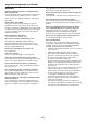
Important safeguards 10.Power sources This projector should be operated only from the type of power source indicated on the marking label. If you are not sure of the type of power, please consult your appliance dealer or local power company. 11.Power-cord protection Power-supply cords should be routed so that they are not likely to be walked on or pinched by items placed upon or against them. Pay particular attention to cords at plugs, convenience receptacles, and points where they exit from the appliance.
Important safeguards (continued) WARNING: other equipment. Also, do not set the projector on the desk which is easily affected by heat. Unplug immediately if there is something wrong with your projector. Do not operate if smoke, strange noise or odor comes out of your projector. It might cause fire or electric shock. In this case, unplug immediately and contact your dealer. Do not look into the air outlet grille when projector is operating. Heat, dust, etc. may blow out of it and hurt your eyes.
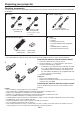
Preparing your projector Checking accessories The following accessories are provided with this projector. Check to be sure that all of the accessories are packed in the package. Cables Power supply parts Mini D-SUB 15-pin D-SUB 9-pin Mini D-SUB 15-pin D-SUB 9-pin Power cord (two) (246C483-10, 246C383-20) RS-232C cable (246C598-10) RGB cable for PC (246C597-10) • Used for projector control by computer.
Preparing your projector (continued) Overview 1 2 3 4 5 6 7 8 9 3 1 2 Remote control sensor (front) Lens Right side panel (air inlet grille/filter) Indicator area Control panel Terminal panel Kensington Security Lock Standard connector Remote control sensor (rear) Left side panel (air outlet grille/lamp cover) 5 Attaching the lens cap 4 � � 6 7 8 To attach the supplied lens cap, push it into the lens section of the projector () and then turn it clockwise ().
Preparing your projector (continued) Bottom side 1 Remote control 24 1 2 3 4 23 22 21 20 5 6 19 7 8 9 10 11 18 17 16 15 14 13 12 1 Adjustment feet 1 2 3 4 5 6 7 8 9 10 11 12 13 14 15 16 17 18 19 20 21 22 23 24 ON ( I ) button HDMI2 button HDMI1 button COMPONENT button AV MEMORY buttons ENTER button MENU button CONTRAST button* BRIGHTNESS button* GAMMA button* ZOOM/FOCUS button LENS SHIFT button NOISE REDUCTION button* COLOR button* SHARPNESS button* COLOR TEMP.
Using the remote control Operational range of the remote control Front of projector 30° Rear of projector 30° 30° 30° Operate the remote control within a distance of 10 m (30 feet) from the projector, pointing the IR beam at the remote control photo-sensor (front or rear) of the projector. • Keep the remote control photo-sensor out of direct sunlight or fluorescent lamp light. • Keep the remote control photo-sensor at least 2 m (6 feet) away from fluorescent lamps.
Setting up your projector Setting up the screen Install the screen perpendicularly to the projector. If the screen can not be installed in such a way, adjust the projection angle of the projector. (See page 12.) • Install the screen and projector so that the projector’s lens is placed at the same height and horizontal position of the screen center. • Do not install the screen where it is exposed to direct sunlight or lighting.
Setting up your projector (continued) Screen size and projection distance (continued) Screen width (SW) Screen H1 50% 50% H1 Screen height (SH) Down side Up side L Left side Right side W1 W1 When the aspect ratio of the screen is 4:3 Screen size (4:3) Diagonal size Height (SH) inch 50 60 70 80 90 100 110 120 150 200 250 300 cm 127 152 178 203 229 254 279 305 381 508 635 762 inch 30 36 42 48 54 60 66 72 90 120 150 180 cm 76 91 107 122 137 152 168 183 229 305 381 457 Size of the projected image
Setting up your projector (continued) Adjusting the position of the projected image To adjust the position of the projected image on the screen, use the LENS SHIFT button. 1. Press the LENS SHIFT button. • The LENS SHIFT menu appears at the center of the screen. 2. Press the p, q, t or u button to move the image position. LENS SHIFT • When the q button is pressed, the image moves down. FAST • When the p button is pressed, the image moves up.
Setting up your projector (continued) Front projection, ceiling mounting Important: • We don’t recommend using the projector at an altitude of 1500 meters or higher. Use at an altitude of 1500 meters or higher may affect the projector’s life. For ceiling mounting, you need the ceiling mount kit designed for this projector. Ask a specialist for installation. For details, consult your dealer.
Viewing video images A. Connecting the projector to video equipment • When the projector and the connected devices are located too close to each other, the projected image may be affected by their interference. • See the owner’s guide of each device for details about its connections. Preparation: • Make sure that the power of the projector and that of the video equipment are turned off.
Viewing video images (continued) Connecting to a video player, etc. Video player, or the like Video cable (option) 1 To VIDEO 2 IN terminal To video output terminal Video player, or the like S-video cable (option) 1 1. Connect one end of the optional video cable to the VIDEO IN terminal of the projector. 2. Connect the other end of the video cable to the video output terminal of the video equipment.
Viewing video images (continued) Connecting to video equipment having a HDMI terminal You can project high-quality images by connecting the HDMI IN terminal of this projector to video equipment having a HDMI output terminal. In addition, this projector supports HDCP and is able to receive encrypted digital video data that are output from DVD players. • Select HDMI as the input source.
Viewing video images (continued) B. Plugging in the power cord • In order to ensure the safety in case of trouble with the projector, use an electrical outlet having an earth leakage breaker to supply the power to the projector. If you do not have such outlet, ask your dealer to install it. 1. Plug the attached power cord into the power cord inlet of this projector. 2. Plug the other end of the power cord into a power outlet. Earthing terminal 2 1 Power cord (example) • The power cords for use in the U.
Viewing video images (continued) C. Projecting images Preparation: • Remove the lens cap. p, q, t, u buttons ENTER button HDMI/COMPUTER button LENS SHIFT button VIDEO button ZOOM/FOCUS button ON ( I ) button HDMI1 button COMPONENT button HDMI2 button S-VIDEO button VIDEO button ENTER button p, q, t, u buttons POWER button ZOOM/FOCUS button LENS SHIFT button POWER indicator STATUS indicator 1. Put the projector into standby mode by pressing the main power switch. The POWER indicator lights up red.
Viewing video images (continued) 10.Adjust with the t or u button to get an approximate size. • When the ENTER button is pressed while “ZOOM” is displayed, the adjustment mode is switched between FAST and STEP. When FAST is selected, the speed of zoom controlled by the t or u button becomes fast, and it becomes slow when STEP is selected. 11.Press the LENS SHIFT button. The LENS SHIFT menu appears at the center of the screen. 12.
Viewing video images (continued) Setting the aspect ratio You can change the aspect ratio of the input video signal (or the ratio of width to height of the image). Change the setting according to the type of the input video signal. : Signal size : Image area Setting 4:3 Aspect ratio changes depending on the input signal. Original image size 16:9 ZOOM1 ZOOM2 STRETCH Squeezed image is expanded to 16:9. CinemaScope image is enlarged and displayed together with subtitles.
Viewing video images (continued) How to change the settings: With the remote control: 1. Press the ASPECT button. • The screen for selecting the aspect ratio appears. 2. Select your desired aspect ratio by pressing the t or u button. • The aspect mode is switched between AUTO, 4:3, 16:9, ZOOM1, ZOOM2, STRETCH, ANAMORPHIC1 and ANAMORPHIC2. • Some modes are not available with certain signals. With the FEATURE menu: (See page 26 for menu setting.) 1. Display the FEATURE menu. 2.
Viewing computer images A. Connecting the projector to a computer Preparation: • Make sure that the power of the projector and that of the computer are turned off. • When connecting the projector to a desktop computer, disconnect the RGB cables that are connected to the monitor. 1. Connect one end of the supplied RGB cable to the COMPUTER IN/COMPONENT VIDEO IN terminal of the projector. COMPUTER IN/ 2. Connect the other end of the RGB cable to the monitor COMPONENT VIDEO IN port of the computer.
Viewing computer images (continued) C. Projecting images Preparation: • Remove the lens cap. p, q, t, u buttons ENTER button HDMI/COMPUTER button LENS SHIFT button ON ( I ) button ZOOM/FOCUS button COMPUTER button ENTER button p, q, t, u buttons POWER button ZOOM/FOCUS button LENS SHIFT button POWER indicator STATUS indicator 1. Put the projector into standby mode by pressing the main power switch. The POWER indicator lights up red.
Viewing computer images (continued) 11.Press the LENS SHIFT button. The LENS SHIFT menu appears at the center of the screen. 12.Press the p or q button to adjust the vertical position and t or u button to adjust the horizontal position of the displayed image. • When the projector cannot be positioned perpendicularly to the screen, adjust the projection angle. (See page 10.) Repeat steps 4 to 5 and 9 to 12, if necessary. To stop projecting: 13.
Menu operation • Menus are not displayed when no signal is supplied to the projector. IMAGE GAMMA MODE CONTRAST BRIGHTNESS COLOR TEMP.
opt. Menu operation (continued) INSTALLATION How to set the menus: opt. GAMMA MODE WXGA (FULL) opt. AUTO POWER ON AUTO POWER INSTALL OFF ATION SPLASH SCREEN SCREEN SIZE SVGA60 OFF ON REVERSE AUTO 2. PressCONTRAST the t or u button 0to select a menu to use. 0 COLOR TEMP. MIDIUM INSTALLATION COLOR SCREEN SIZE TINT VERTICAL LOCATION SHARPNESS LAMP MODE opt.
Menu operation (continued) 2. INSTALLATION menu opt. INSTALLATION KEYSTONE LAMP MODE ON AUTO POWER ON AUTO POWER OFF SPLASH SCREEN BACK COLOR IMAGE REVERSE TRIGGER OUT TEST PATTERN LENS LOCK AV MEMORY 1 0 STANDARD OFF OFF ON BLUE OFF OFF CROSS HATCH OK 2.
Menu operation (continued) 3. FEATURE menu opt. FEATURE AV MEMORY 1 ASPECT AUTO DISPLAY INPUT PASSWORD FUNCTION MENU POSITION ? 1. MENU DIMMER OFF CINEMA MODE AUTO VIDEO SIGNAL AUTO SETUP AUTO SCART INPUT AË OFF English LANGUAGE OK RESET ALL 3. FEATURE menu ITEM ASPECT SETTING AUTO 4:3 16:9 ZOOM1 ZOOM2 STRETCH ANAMORPHIC1 ANAMORPHIC2 PASSWORD FUNCTION MENU POSITION MENU DIMMER CINEMA MODE 2 options ON / OFF AUTO VIDEO SIGNAL VIDEO FILM 8 options SETUP AUTO OFF 3.75% / 7.
Menu operation (continued) 4. SIGNAL menu 5. USER menu opt. SIGNAL R RG GB B USER AV MEMORY 1 CLAMP POSITION 1 CLAMP WIDTH 1 HORIZ. POSITION 0 VERT. POSITION 0 FINE SYNC. 0 LPF TRACKING 0 SHUTTER(U) 0 COMPUTER INPUT AUTO OVER SCAN 100% HOLD ON USER OK ? VERT. SYNC AUTO OFF SHUTTER(L) 0 SHUTTER(LS) 0 SHUTTER(RS) 0 4. SIGNAL menu ITEM HORIZ. POSITION VERT. POSITION FINE SYNC.
Menu operation (continued) 6. INFORMATION menu opt. INFORMATION LAMP TIME(LOW) INPUT 0H COMPUTER RESOLUTION 1024X768 VERTICAL FREQUENCY 75.04 Hz HORIZONTAL FREQUENCY 60.02 KHz SYNC. TYPE 5wire R G B H V 6. INFORMATION menu ITEM LAMP TIME(LOW) INPUT RESOLUTION VERTICAL FREQUENCY HORIZONTAL FREQUENCY SYNC. TYPE DESCRIPTION This item shows a lamp operating time (hour) calculated based on that LAMP MODE is LOW.
Adjusting projected images To adjust the brightness (CONTRAST and BRIGHTNESS): You can make adjustments for the brightness of the projected image using the menu. (See page 26 for menu setting.) 1. Display the IMAGE menu. 2. Select CONTRAST or BRIGHTNESS by pressing the p or q button. 3. Adjust the selected item by pressing the t or u button. To cancel the menu: 4. Press the MENU button. CONTRAST Select to adjust the contrast of the image.
Adjusting projected images (continued) To adjust the tone of white (COLOR TEMP.): You can select a preset color temperature (white tone) using the menu. (See page 26 for menu setting.) 1. Display the IMAGE menu. 2. Select COLOR TEMP. by pressing the p or q button. 3. Select your desired color temperature by pressing the t or u button. The color temperature of each option is as follows: COOL: Approx. 9300K, MEDIUM: Approx. 6500K (D65), WARM: Approx. 5800K. To cancel the menu: 4. Press the MENU button.
Adjusting projected images (continued) To adjust the ratio of change in brightness (GAMMA MODE): You can select a preset gamma mode using the menu. (See page 26 for menu setting.) 1. Display the IMAGE menu. 2. Select GAMMA MODE by pressing the p or q button. 3. Select your desired gamma mode by pressing the t or u button. To cancel the menu: 4. Press the MENU button.
Adjusting projected images (continued) This projector automatically and properly projects video signals supplied from the computer. However, some video signals may not be projected, depending on the type of the computer. In such a case, press the AUTO POSITION button. (See page 24.) When the signal is still not projected properly, adjust the projected image using the SIGNAL menu. How to adjust the image supplied from the computer using the menu: Carry out the following procedures according to the symptoms.
Advanced features Password function To cancel the password function: 1. Display the FEATURE menu. 2. Press the p or q button to select PASSWORD FUNCTION. 3. Press the ENTER button. • The screen for canceling the password function will appear. This projector is equipped with the password function that is designed for prevention of theft and wrong operation by children and restriction on operation by other than specified users. The password function has two modes as follows. DISPLAY INPUT ..........
Replacing the lamp This projector is equipped with a lamp to project images. This lamp is a consumable. It may burn out or its brightness may decrease during use. In such cases, replace the lamp with a new one as soon as possible. Be sure to replace the lamp with a new lamp sold separately that is exclusive to this projector. Contact your dealer for purchase of the lamp. Spare lamp VLT-HC6800LP Warning: • Be careful not to drop the lamp fixing screws inside of the projector.
Replacing the lamp (continued) To replace the lamp: 9. Tighten up the screws (d) using a Phillips screwdriver (+). 1. Turn off the main power switch and unplug the power cord. 2. Loosen two screws (a) using a Phillips screwdriver (+) and remove the left side panel from the projector. (d) 10.Tighten up the screw (b) using a Phillips screwdriver (+) to secure the lamp cover (c). (a) (b) 3. Loosen the screw (b) using a Phillips screwdriver (+), and remove the lamp cover (c). (b) (c) 11.
Replacing the lamp (continued) When removing the lamp from the ceiling-mounted projector When removing the lamp from the ceiling-mounted projector, use the lamp replacement tray packed with the projector or option lamp to prevent glass fragments from scattering. • Assemble the lamp replacement tray according to the procedure shown on it. 1. Follow steps 1 to 5 on page 37. 2. Attach the lamp replacement tray to the projector as shown in the figure. 3.
Maintenance Warning: • Never use flammable air duster or other materials when cleaning the air-filter. Flammable substances may ignite causing fire or breakdown when the lamp is illuminated. • Do not use flammable solvents (benzene, thinner, etc.) and flammable aerosols when cleaning the projector body and lens. Flammable substances may ignite causing fire or breakdown while the lamp is illuminating.
Troubleshooting Before asking for repair of the projector, check the following. If the symptom persists, stop using the projector, be sure to unplug the power plug, and then contact your dealer. No image appears on the screen. Problem Solution Power can not be turned on. • Check whether the indicators are on or off and how they are lightning. POWER STATUS Solution • Connect the power cord to the projector. • Plug the power cord into a wall outlet. Off Off • Turn on the main power switch.
Troubleshooting (continued) No image appears on the screen. (continued) Problem The screen for entering the password appears. “NO SIGNAL” is displayed. Solution • PASSWORD FUNCTION in the FEATURE menu has been set to DISPLAY INPUT to enable the password lock. Enter the password or contact the person in charge of management of the projector. (See page 35.) • Turn on the power of the connected device, or check whether there is something wrong with the connected device.
Troubleshooting (continued) Images are not displayed correctly. (continued) Problem Solution Different color tint. • When comparing images projected by two projectors, tints in the displayed images may be different because of variation between their optical components. This is not a malfunction.
Indicators This projector has two indicators, each of which shows the operation condition of the projector. The following offer solutions to possible problems. If these problem persist, turn the projector off and consult your dealer. POWER indicator STATUS indicator Normal condition POWER STATUS Off Steady red Blinking green Blinking green Steady green Steady green CONDITION NOTE Stand-by Lamp stand-by for power-off The power cannot be turned on by pressing the POWER button.
Specifications The specifications and outside appearance of the projector are subject to change without prior notice. Type LCD projector Model HC6800 Display technology 0.74-inch LCD panel: 3 pieces (for R, G, B) (aspect ratio 16:9) Pixel: 1920 x 1080 = 2073600 pixels Total 6220800 pixels Projection lens F 1.8 - 2.3 f= 23.5 - 37.6 mm Light-source lamp 170 W Image size (projection distance) 50” min. to 300” max. (projection distance 1.5 to 9.5 m (max.
Specifications (continued) Specification of RGB signals in each computer mode of the projector Signal mode TV60, 480i (525i) TV50, 576i (625i) 1080i 60 (1125i 60) 1080i 50 (1125i 50) 480p (525p) 576p (625p) 720p 60 (750p 60) 720p 50 (750p 50) 1080p 60 (1125p 60) 1080p 50 (1125p 50) 1080p 24 (1125p 24) PC98 CGA70 VGA60 VGA72 VGA75 VGA85 SVGA56 SVGA60 SVGA72 SVGA75 SVGA85 XGA60 XGA70 XGA75 XGA85 MAC13 MAC16 MAC19 HP75 SXGA60 UXGA60 Resolution (H x V) – – – – – – – – – – – 640 x 400 640 x 400 640 x 480 640 x
Specifications (continued) Connectors COMPUTER IN/COMPONENT VIDEO IN (Mini D-SUB 15-pin) SERIAL (D-SUB 9-pin) 5 5 1 9 6 10 6 15 Pin No. Name I/O 1 – – 2 TXD IN 3 RXD OUT 4 – – 5 GND – 6 – – 7 – – 8 – – 9 – – 1 11 Pin No. Spec. 1 R(RED)/PR/CR 2 G(GREEN)/Y 1 19 2 18 3 B(BLUE)/PB/CB PIN No.
MITSUBISHI ELECTRIC CORPORATION 1 Zusho Baba, Nagaokakyo-City, Kyoto Japan A