52 OPERATION GUIDE
Contents Basic Operation ...............................................................3 Menu Items .......................................................................5 Displaying the menu screen .........................................5 Menu item details .........................................................6 Adjustments for PC screen display ............................10 Initialization (Reset)/Functional Restriction Setting ... 11 Controlling the Monitor with a PC (RS-232C) ..............
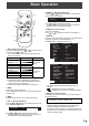
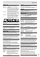
Basic Operation 5. BRIGHT +/- (Backlight adjustment) or displays the BRIGHT menu when the Pressing menu screen is not displayed. 1 BRIGHT 2 15 3 4 Press or to adjust the brightness. * If you do not press any buttons for about 4 seconds, the BRIGHT menu automatically disappears. 5 6. SIZE (Screen size selection) The menu is displayed. Press or to select the screen size. (See page 4.) 6 7 7. DISPLAY Displays monitor information.
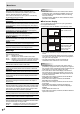
Basic Operation Switching the screen size Even when the screen size is changed, the display may remain the same depending on the input signal. WIDE ZOOM 1 PC input Displays image so it fills the entire screen. AV input An image with a 4:3 aspect ratio is stretched to fill the entire screen. PC input An image with a 4:3 aspect ratio is enlarged to fill the entire screen without changing the aspect ratio. The edges of the image may be cut off.
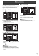
Menu Items Displaying the menu screen Menu screen display Video and audio adjustment and settings of various functions are enabled. This section describes how to use the menu items. See pages 6 to 8 for details of each menu items. 1 SCREEN PICTURE Example of operation (Adjusting CONTRAST in the PICTURE menu) 1. Press MENU SCREEN to display the menu screen.
Menu Items Menu item details The menu will differ depending on the input mode. SCREEN AUTO (PC3/PC4) The CLOCK, PHASE, H-POS, and V-POS are automatically adjusted. Pressing performs adjustment. Use this automatic adjustment when you use the PC3 input terminal or PC4 input terminals to display a PC screen for the first time or when you change the setting of the PC. (See page 10.) CLOCK (PC3/PC4) Adjusts frequency for sampling clock for applicable video.
Menu Items SCREEN MOTION Residual images are reduced by moving the screen. PATTERN 1 .... The whole screen moves vertically and horizontally. PATTERN 2 .... A black screen spreads from the bottom of the screen and then shrinks to the bottom of the screen. If the monitor is installed in the vertical orientation, a black screen spreads from the left end of the screen and then shrinks to the left end of the screen. PATTERN 3 .... A black bar moves from the left end to the right end of the screen.
Menu Items COLOR SYSTEM (AV4/AV5) Select the color system of the AV equipment which is connected to AV4 and AV5 input terminal. (AUTO / PAL / PAL-60 / SECAM / NTSC3.58 / NTSC4.43) When AUTO is selected, the color system is automatically set according to the input signal. ENLARGE (PC input) ENLARGE H Sets the number of screen splits (number of monitors) in the horizontal direction used for the enlargement. (See page 9.
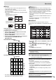
Menu Items Enlarge TIPS • You can align several monitors and integrate them into a single large screen to display. • Up to five monitors can be aligned in both the horizontal and vertical directions. • Each monitor displays enlarged views of separated images. (Example) Horizontal direction: 2 monitors Vertical direction: 2 monitors • AV input signals cannot be used for the Enlarge function.
Menu Items (5) INPUT Specifies the input mode at power-on. When not specifying, the screen at the previous power-off appears. Input modes displayed on “PC1/AV1” depend on DVI SELECT settings. Input modes displayed on “PC2/AV2” depend on HDMI SELECT settings. Input modes displayed on “PC4/AV3” depend on BNC SELECT settings. Caution • Do not switch off the main power after setting the SCHEDULE. • Specify the correct date and time. (See page 7.
Initialization (Reset)/Functional Restriction Setting You can return the settings to their factory-preset values and restrict operations. 1. After pressing , SIZE for about 5 seconds, press , and , in that order. FUNCTION 1/1 ALL RESET ADJUSTMENT LOCK OFF RS-232C/LAN UNLOCKED OSD DISPLAY ON LED ON TEMPERATURE ALERT LED STATUS ALERT OFF END…[MENU] 2. Select and set the items. ALL RESET Resets the settings to the factory default settings.
Controlling the Monitor with a PC (RS-232C) You can control this monitor from a PC via RS-232C (COM port) on the PC. You can also connect multiple monitors via a daisy chain by using a PC. By assigning ID numbers to each monitor (see page 13), you can make input mode selection/adjustment or can check the status of a specific monitor. Caution • To control the monitor via RS-232C, set RS-232C/LAN SELECT to RS-232C. • You cannot use RS-232C and LAN control simultaneously.
Controlling the Monitor with a PC (RS-232C) Response code format Communication interval When a command has been executed correctly • After OK or ERR is returned, you must send the following commands. To set a timeout for the command response, specify 10 seconds or longer. • Provide an interval of 100 ms or more between the command response and the transmission of the next command. VOLM0020 OK O K Return code (0DH, 0AH) A response is returned after a command is executed.
Controlling the Monitor with a PC (RS-232C) Commands for ID control The command examples shown on this page assume the following connection and ID number set up. ID number: 1 ID number: 2 ID number: 3 ID number: 4 IDST .........A monitor receiving this command sets its own ID number in the parameter field. Example: IDST0001 001 ← The ID number of this monitor is set to 1. OK IDLK ........The parameter of this command sets the ID number of the monitor.
Controlling the Monitor with a PC (RS-232C) Repeater control This system has a function to allow setting of multiple monitors connected in a daisy chain using a single command. This function is called repeater control. You can use Repeater control function without assigning ID numbers. [Example] Set 1 Set 2 Set 3 Set 4 * If monitors are connected as shown above, you can execute a command like “Set all monitors’ input settings to PC1 DVI-D”.
Controlling the Monitor with a PC (RS-232C) RS-232C command table How to read the command table Command: Command field (See page 12.) Direction: W When the “Parameter” is set in the parameter field (see page 12), the command functions as described under “Control/Response Contents”. ?” or “???+” R The returned value indicated under “Reply” can be obtained by setting “????”, “ (repeater control) in the parameter field (see page 12). Parameter: Parameter field (See page 12.
Controlling the Monitor with a PC (RS-232C) PICTURE menu Command Direction AUTO Function AGIN W CONTRAST CONT WR 0-60 0-60 0-127 on PC3/PC4. BLACK LEVEL BLVL WR 0-60 0-60 0-127 on PC3/PC4. TINT TINT WR 0-60 0-60 COLORS COLR WR 0-60 0-60 0-24 SHARPNESS ADVANCED (When the input mode is AV.) Parameter Reply Control/Response contents 1 When the input mode is PC3, PC4.
Controlling the Monitor with a PC (RS-232C) SETUP menu Command Direction OSD H-POSITION Function OSDH WR 0-100 0-100 OSD V-POSITION OSDV WR 0-100 0-100 SCREEN MOTION SCSV WR 0-4 0-4 MOTION TIME 1 MTIM WR 0-20 0-20 PATTERN1 MINT WR 10-990 10-990 PATTERN2-4 MINT WR 5-20 5-20 MOTION TIME 2 Parameter Reply Control/Response contents * B 0: OFF, 1-4: PATTERN1-4 B B Per 10 seconds B Per second MONITOR STDR WR 0-1 0-1 LANGUAGE LANG WR 14 14 ENGLISH 0: LANDSCAPE,
Controlling the Monitor with a PC (RS-232C) ENLARGE menu (When the input mode is PC) Function Command Direction EMAG WR 0-4 EMHV WR 11-55 11-55 1 x 1 (OFF) to 5 x 5 (“m x n” is expressed as “mn”, where m and n are the numbers of monitors specified for the longest direction and the shortest direction respectively.
Controlling the Monitor with a PC (RS-232C) PIP/PbyP menu Function PIP MODES PIP SIZE PIP POS Command Direction MWIN WR MPSZ WR THE LONGEST DIRECTION MHPS W THE SHORTEST DIRECTION MVPS PIP POS LD+SD BATCH Parameter Reply 0-3 1-12 1-12 B 0-100 W B 0-100 B R MPOS 0-100 0-100,0-100 R * B B 0-100 R W Control/Response contents 0-3 0: OFF, 1: PIP, 2: PbyP, 3: PbyP2 B Specify the position in MPOSxxxyyy format.
Controlling the Monitor with a PC (LAN) Your monitor can be connected to a LAN allowing you to control it from a PC on the LAN. You can also configure the monitor to send e-mail notification when it has a problem. The connection requires a commercially available LAN cable (UTP cable, Category 5, straight through). Network (LAN) Settings to connect to a LAN Set the monitor’s IP address and subnet mask to match the settings of your LAN.
Controlling the Monitor with a PC (LAN) To set from a PC When the monitor is connected to a PC, LAN settings can be configured via PC. Set up process (1) Connect your monitor to a PC (2) Specify the PC’s IP address (3) Configure the monitor’s LAN settings 7. Temporarily change the IP address and subnet mask. To access the monitor as it is shipped from the factory, set as follows. • IP Address: 192.168.150.3 • Subnet Mask: 255.255.255.
Controlling the Monitor with a PC (LAN) 5. Click on “LAN SETUP” under NETWORK. Controlling with a PC Basic operation You use Internet Explorer on a PC on the LAN to control the monitor. 1. Launch Internet Explorer on the PC. 2. In the “Address” box, type “http://” followed by your monitor’s IP address followed by “/”, then press the Enter key. When prompted to enter a user name and password, type the user name and password that you specified in the security settings (see page 25), and click [OK].
Controlling the Monitor with a PC (LAN) INFORMATION ADJUSTMENT Information about this monitor appears. You can adjust these settings which are also available on the monitor’s menu. • SCREEN (See page 6.) • PICTURE (See Page 6.) • PICTURE (ADVANCED) (See Page 6.) • AUDIO (See page 6.) • SETUP (See page 7.) • OPTION (See page 7.) • SCHEDULE (See page 9.) • ENLARGE (See page 9.) • PIP/PbyP (See page 8.) • FUNCTION (See page 11.
Controlling the Monitor with a PC (LAN) NETWORK (LAN SETUP) NETWORK (SECURITY) This screen allows you to set the settings necessary when the monitor is connected to a LAN. This screen allows you to specify the security-related settings. DHCP CLIENT If your LAN has a DHCP server and you wish to obtain an address automatically, change this setting to “ON”. To set the address manually, set this to “OFF”. IP ADDRESS If the DHCP CLIENT is set to “OFF”, specify an IP address.
Controlling the Monitor with a PC (LAN) NETWORK (GENERAL) MAIL (ORIGINATOR) This screen allows you to specify the general LAN settings. This screen allows you to configure the e-mail sent periodically or when the monitor has an error. The settings depend on the configuration of your LAN. Ask your LAN administrator for details. MONITOR NAME Specify a name for this monitor as it should appear on the Internet Explorer screen.
Controlling the Monitor with a PC (LAN) MAIL (RECIPIENT) MAIL (PERIODICAL) This screen allows you to specify the recipients of the e-mail sent periodically or when the monitor has an error. When PERIODICAL for CONDITION of MAIL (RECIPIENT) is checked, set the date and time to send the mail. RECIPIENT E-MAIL ADDRESSES Specify the e-mail addresses to send error notification e-mail to. CONDITION Specify the conditions to send mails.
Controlling the Monitor with a PC (LAN) SERVICE & SUPPORT (URL INFORMATION) You can display a specific URL in the URL INFORMATION field on the INFORMATION screen when an error occurs in the monitor. (See page 24.) URL INFORMATION Enter a URL to display when an error occurs on the monitor. Up to 64 alphanumeric characters or symbols can be used. CONDITION Specify the condition to display the URL. CONFIRMATION The home page of the specified URL is displayed.
MEMO 29 E
MITSUBISHI Contact Information North America Europe MESCA (Mitsubishi Electric Sales Canada Inc.) http://www.mitsubishielectric.ca Information Technologies Group, 4299 14th Avenue, Markham, Ontario L3R 0J2, Canada Sales Phone :+1-(905) 475-7728 Fax :+1-(905) 475-7958 E-mail :projectors@mitsubishielectric.ca Technical Phone :+1-(905) 475-7728 Fax :+1-(905) 475-7958 Customer Care E-mail :support@mitsubishielectric.ca MEU-FRA (Mitsubishi Electric Europe B.