OPERATION MANUAL
Important Information DECLARATION OF CONFORMITY This device complies with Part 15 of FCC Rules. Operation is subject to the following two conditions. (1) This device may not cause harmful interference, and (2) this device must accept any interference received, including interference that may cause undesired operation. U.S. Responsible Party: Mitsubishi Digital Electronics America, Inc. Address: 9351 Jeronimo Road, Irvine, California 92618 U.S.A. Tel. No.
IMPORTANT INFORMATION FOR CUSTOMERS IN U.K.
IMPORTANT INFORMATION (Continued) • When operating the LCD monitor with an AC 100-120V power supply in North America, use a power supply cord provided with this monitor. • When operating the LCD monitor with an AC 220-240V power supply in Europe, use a power supply cord provided with this monitor. • In UK, use a BS-approved power cord with molded plug having a black (10A) fuse installed for use with this monitor. If a power cord is not supplied with this monitor, please contact your supplier.
DEAR MITSUBISHI CUSTOMER Thank you for your purchase of a MITSUBISHI LCD product. To ensure safety and many years of trouble-free operation of your product, please read the Safety Precautions carefully before using this product. SAFETY PRECAUTIONS Electricity is used to perform many useful functions, but it can also cause personal injuries and property damage if improperly handled. This product has been engineered and manufactured with the highest priority on safety.
SAFETY PRECAUTIONS (Continued) 15. Replacement parts — In case the product needs replacement parts, make sure that the service person uses replacement parts specified by the manufacturer, or those with the same characteristics and performance as the original parts. Use of unauthorised parts can result in fire, electric shock and/or other danger. 16.
TIPS AND SAFETY INSTRUCTIONS - The TFT colour LCD panel used in this monitor is made with the application of high precision technology. However, there may be minute points on the screen where pixels never light or are permanently lit. Also, if the screen is viewed from an acute angle there may be uneven colours or brightness. Please note that these are not malfunctions but common phenomena of LCDs and will not affect the performance of the monitor.
Contents Introduction IMPORTANT INFORMATION............................................1 DEAR MITSUBISHI CUSTOMER .....................................3 SAFETY PRECAUTIONS..................................................3 TIPS AND SAFETY INSTRUCTIONS ...............................5 Supplied Accessories......................................................7 Part Names .......................................................................7 Front view.........................................................
Supplied Accessories If any component should be missing, please contact your dealer. Liquid Crystal Display: 1 Remote control unit: 1 Stand hole protection cover: 2 Power cord: 1 R-6 battery: 2 CD-ROM (Utility Disk for Windows): 1 Operation manual: 1 * MITSUBISHI ELECTRIC CORPORATION holds authorship rights to the Utility Disk programme. Do not reproduce it without permission. * For environmental protection! Do not dispose of batteries in household waste.
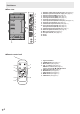
Part Names nRear view 16 1 2 3 4 5 6 7 8 9 10 11 12 1. 2. 3. 4. 5. 6. 7. 8. 9. 10. 11. 12. 13. 14. 15. 16. RS-232C output terminal (D-sub 9 pin) (See page 24.) RS-232C input terminal (D-sub 9 pin) (See page 24.) AV3 input terminal (BNC) (See page 10.) AV2 input terminals (BNC) (See page 10.) PC3 input terminals (BNC) (See page 10.) PC audio input terminal (See page 10.) PC2 input terminal (Mini D-sub 15 pin) (See page 10.) AV audio input terminals (See page 10.
How to Install the Monitor Mounting precautions • Since the monitor is heavy, consult your dealer before installing, removing or moving the monitor. • When installing, removing or moving the monitor, ensure that this is carried out by at least 3 people. • When moving the monitor, be sure to hold it with the handles both on the rear and the unit bottom. Do not hold the LCD panel. This may cause product damage, failure, or injury. • Install the monitor with the surface perpendicular to a level surface.
Connecting Peripheral Equipment Connection with AV equipment Caution • Be sure to turn off the main power switch and disconnect the plug from the power outlet before connecting/ disconnecting cables. Also, read the manual of the equipment to be connected. • Be careful not to mix up the input terminal with the output terminal when connecting cables. Mixing up the input and output terminals may cause malfunctions and the other problems.
Connecting Peripheral Equipment Other terminals Connecting multiple monitors PC/AV audio output terminals • Audio from the equipment connected to the AV audio input terminals or PC audio input terminal is output. Connect to the audio input terminals of the connected equipment using a commercially available audio cable (RCA). • The audio output varies depending on the input mode selection. (See page 15.) • The volume level can be adjusted using the volume adjustment. (See page 15.
Connecting the Power Cord Caution • Do not use a power cord other than the one supplied with the monitor. 1. Turn off the main power switch. 2. Plug the power cord (supplied) into the AC input terminal. 3. Plug the power cord (supplied) into the AC power outlet.
Removing the Temporary Stand and the Handles nRemoving the Temporary Stand nRemoving the Handles Prepare wall-hanging brackets or a stand to mount the monitor unit. Read the manual for the brackets or stand for the proper mounting procedure. (The screw holes for mounting brackets (M10 x 4 holes) are provided on the rear of the monitor.) The handles are detachable. Caution • The monitor is heavy. Make sure to handle the monitor with at least 3 people.
Turning Power On/Off TIPS Caution • Turn on the monitor first before turning on the PC or playback device. Turning on the main power • If the monitor is in the input signal standby mode and you press the POWER button on the remote control unit, the monitor enters standby mode. • You can turn on/off the monitor by pressing the power switch of the monitor. • Setting the SCHEDULE flashes the power LED alternately in red and orange in standby mode.
Basic Operation 5. BRIGHT +/- (Backlight adjustment) or displays the BRIGHT menu when the Pressing menu screen is not displayed. 1 BRIGHT 2 3 15 Press or to adjust the brightness. * If you do not press any buttons for about 4 seconds, the BRIGHT menu automatically disappears. 4 5 6. SIZE (Screen size selection) The menu is displayed. Press or to select the screen size. (See page 16.) 7. DISPLAY Displays monitor information.
Basic Operation nSwitching the screen size Even when the screen size is changed, the display may remain the same depending on the input signal. WIDE ZOOM 1 PC input Displays image so it fills the entire screen. AV input An image with a 4:3 aspect ratio is stretched to fill the entire screen. PC input An image with a 4:3 aspect ratio is enlarged to fill the entire screen without changing the aspect ratio. The edges of the image may be cut off.
Menu Items Displaying the menu screen nMenu screen display Video and audio adjustment and settings of various functions are enabled. This section describes how to use the menu items. See pages 18 to 20 for details of each menu items. 1 SCREEN PICTURE nExample of operation (Adjusting CONTRAST in the PICTURE menu) 1. Press MENU SCREEN to display the menu screen.
Menu Items Menu item details The menu will differ depending on the input mode. nSCREEN (PC2/PC3) Changes the colour mode on the screen. The colour mode on the screen can also be changed using a remote control unit. (See page 15.) * sRGB is PC input only. See page 15 for details. AUTO WHITE BALANCE The CLOCK, PHASE, H-POS, and V-POS are automatically adjusted. Pressing performs adjustment.
Menu Items nSETUP nOPTION OSD H-POSITION DATE/TIME SETTING Adjusts the horizontal display position of menu screen. to select the date or Set the date and time. Press and time, and press or to change the numerical values. Set the date in “Year/Month/Day” order. Set the time on a 24-hour basis. OSD V-POSITION Adjusts the vertical display position of menu screen. SCREEN MOTION Residual images are reduced by moving the screen. PATTERN 1 .... The whole screen moves vertically and horizontally. PATTERN 2 ..
Menu Items nENLARGE (PC input) ENLARGE MODE Sets the number of screen splits used for the enlargement. (See page 21.) ENLARGE POS Specify the split screen to be displayed when the enlargement function is used. (See page 21.) TIPS • When WHITE BALANCE is set to THRU, BLACK LEVEL, CONTRAST and GAMMA cannot be set. • If COLOR MODE is set to sRGB or VIVID, the following items cannot be set.
Menu Items nEnlarge nSCHEDULE You can align 4, 9, 16, or 25 monitors and integrate them into a single large screen to display. Enlarged views of separated images are displayed in each monitor. You can set the time to switch the monitor on and off. Set this function with “SCHEDULE” in the OPTION menu. (See page 19.) PC2 ANALOG SCHEDULE XXXX/XX/XX XXX XX:XX:XX Original image No. 4 monitors 2 (1) POWER (2) TIME (4) 0 6 3 0 1 7 4 1 8 5 2 OK…[MENU] V: 60 Hz H: 48.4 kHz 1.
Menu Items Caution • Do not switch off the main power after setting the SCHEDULE. • Specify the correct date and time. (See pages 14 and 19.) SCHEDULE does not function unless the date and time are specified. • Check regularly that the set date and time are correct. TIPS • Up to 8 SCHEDULE items can be registered. • Setting the SCHEDULE flashes the power LED alternately in red and orange in standby mode.
Initialisation (Reset)/Functional Restriction Setting You can return the settings to their factory-preset values and restrict operations. 1. After pressing , SIZE , and for about 5 seconds, press , in that order. FUNCTION 1/1 ALL RESET ADJUSTMENT LOCK OFF OSD DISPLAY ON LED RS-232C ON UNLOCKED END···[MENU] 2. Select and set the items. ALL RESET Resets the settings to the factory default settings. MENU , select “ON” and then press .
Controlling the Monitor with a PC You can control this monitor from a PC via RS-232C (COM port) on the PC. You can also connect multiple monitors via a daisy chain by using a PC. By assigning ID numbers to each monitor (see page 25), you can make input mode selection/adjustment or can check the status of a specific monitor.
Controlling the Monitor with a PC nResponse code format nCommunication interval When a command has been executed correctly • After OK or ERR is returned, you must send the following commands. To set a timeout for the command response, specify 10 seconds or longer. • Provide an interval of 100 ms or more between the command response and the transmission of the next command. O K Return code (0DH, 0AH) A response is returned after a command is executed.
Controlling the Monitor with a PC nCommands for ID control The command examples shown on this page assume the following connection and ID number set up. ID number: 1 ID number: 2 ID number: 3 ID number: 4 IDLK ........The parameter of this command sets the ID number of the monitor. The monitor is subject to all subsequent commands. Example: IDLK0002 WAIT IDST .........A monitor receiving this command sets its own ID number in the parameter field.
Controlling the Monitor with a PC nRepeater control This system has a function to allow setting of multiple monitors connected in a daisy chain using a single command. This function is called repeater control. You can use Repeater control function without assigning ID numbers. [Example] Set 1 Set 2 Set 3 Set 4 * If monitors are connected as shown above, you can execute a command like “Set all monitors’ input settings to PC1 DIGITAL”.
Controlling the Monitor with a PC RS-232C command table How to read the command table Command: Command field (See page 24.) Direction: W When the “Parameter” is set in the parameter field (see page 24), the command functions as described under “Control/Response Contents”. R The returned value indicated under “Reply” can be obtained by setting “????”, “ ?” or “???+” (repeater control) in the parameter field (see page 24). Parameter: Parameter field (See page 24.
Controlling the Monitor with a PC PICTURE menu Function AUTO Command Direction AGIN W Parameter Reply Control/Response contents 1 When the input mode is PC2, PC3. CONTRAST CONT WR 0-60 0-60 0-127 on PC2/PC3. BLACK LEVEL BLVL WR 0-60 0-60 0-127 on PC2/PC3. TINT TINT WR 0-60 0-60 When the input mode is AV.
Controlling the Monitor with a PC OPTION menu Command Direction DATE/TIME SETTING Function DATE WR AABBCCDDEE Parameter AABBCCDDEE Reply AA: Year, BB: Month, CC: Day, DD: Time, EE: Minute Control/Response contents Yes * SCHEDULE SC01SC08 WR ABCDEFFGGH ABCDEFFGGH Schedule of a specified number A: Schedule 0 = Not effective, 1 = Effective B: Power 0 = OFF, 1 = ON C: Day of the week 1 0 = Only once, 1 = Every week, 2 = Every day D: Day of the week 2 0 = Sunday, 1 = Monday through 6 = Saturda
Controlling the Monitor with a PC Initialisation/Functional Restriction Setting (FUNCTION) menu Command Direction ALL RESET Function RSET W Parameter Reply Control/Response contents ADJUSTMENT LOCK ALCK WR 0-2 0-2 0: OFF OSD DISPLAY LOSD WR 0-1 0-1 0: ON, 1: OFF Yes LED OFLD WR 0-1 0-1 0: ON, 1: OFF Yes 0 * No Yes Others Function SCREEN SIZE (PC) Command Direction WIDE WR Parameter Reply 1-5 SCREEN SIZE (AV) WIDE WR 1-5 VOLUME VOLM WR 0-31 0-1 MUTE INFORMATION Con
Troubleshooting Before calling for repair services, make sure following checks for possible remedies to the encountered symptoms. There is no picture or sound. • Is the power cord disconnected? (See page 12.) • Is the main power switch set to “OFF”? (See page 14.) • Is the monitor in standby mode (the power LED illuminating in orange)? (See page 14.) • Make sure correct input mode is selected. (See page 15.) • If any external equipment is connected, make sure the equipment is operating (playing back).
Specifications nProduct Specifications Model LCD element Max. resolution (pixels) Max. colours Pixel pitch Viewing angle Screen active area (mm) Computer input signal Sync signal LDT651P 65" wide (163.9 cm diagonal) ASV low-reflection black TFT LCD 1080 x 1920 16.77 M colours (8 bits/colour) 0.744 mm (H) x 0.744 mm (V) 176° right/left/up/down (contrast ratio ≥ 10) 804 x 1428 Digital (DVI 1.0 standard-compliant), Analogue RGB (0.
Specifications nDimensional Drawings Note that the values shown are approximate values. 871 Unit: mm 650 Opening height (1432) 1509 1572 Screw holes for mounting brackets Opening width (807) 40 When mounting the monitor, read the manual of the brackets or stand for their mounting procedure. The screw holes for mounting brackets (M10 x 4 holes) are provided on the rear of the monitor. Note that screw hole depth of the monitor is 30 mm.
Specifications nPower management This monitor conforms to VESA DPMS and DVI DMPM. Both your video card and computer must support the same standard in order for the monitor’s power management function to work.
MEMO E 36
MITSUBISHI Contact Information North America Europe MESCA (Mitsubishi Electric Sales Canada Inc.) http://www.mitsubishielectric.ca Information Technologies Group, 4299 14th Avenue, Markham, Ontario L3R 0J2, Canada Sales Phone :+1-(905) 475-7728 Fax :+1-(905) 475-7958 E-mail :projectors@mitsubishielectric.ca Technical Phone :+1-(905) 475-7728 Fax :+1-(905) 475-7958 Customer Care :support@mitsubishielectric.ca E-mail MEU-FRA (Mitsubishi Electric Europe B.