General-Purpose AC Servo J2-Super Series General-Purpose Interface MODEL MR-J2S- A SERVO AMPLIFIER INSTRUCTION MANUAL H
Safety Instructions (Always read these instructions before using the equipment.) Do not attempt to install, operate, maintain or inspect the servo amplifier and servo motor until you have read through this Instruction Manual, Installation guide, Servo motor Instruction Manual and appended documents carefully and can use the equipment correctly. Do not use the servo amplifier and servo motor until you have a full knowledge of the equipment, safety information and instructions.
1. To prevent electric shock, note the following: WARNING Before wiring or inspection, switch power off and wait for more than 15 minutes. Then, confirm the voltage is safe with voltage tester. Otherwise, you may get an electric shock. Connect the servo amplifier and servo motor to ground. Any person who is involved in wiring and inspection should be fully competent to do the work. Do not attempt to wire the servo amplifier and servo motor until they have been installed.
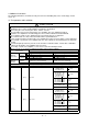
. Additional instructions The following instructions should also be fully noted. Incorrect handling may cause a fault, injury, electric shock, etc. (1) Transportation and installation CAUTION Transport the products correctly according to their masses. Stacking in excess of the specified number of products is not allowed. Do not carry the servo motor by the cables, shaft or encoder. Do not hold the front cover to transport the servo amplifier. The servo amplifier may drop.
CAUTION Securely attach the servo motor to the machine. If attach insecurely, the servo motor may come off during operation. The servo motor with reduction gear must be installed in the specified direction to prevent oil leakage. Take safety measures, e.g. provide covers, to prevent accidental access to the rotating parts of the servo motor during operation. Never hit the servo motor or shaft, especially when coupling the servo motor to the machine. The encoder may become faulty.
(4) Usage CAUTION Provide an external emergency stop circuit to ensure that operation can be stopped and power switched off immediately. Any person who is involved in disassembly and repair should be fully competent to do the work. Before resetting an alarm, make sure that the run signal of the servo amplifier is off to prevent an accident. A sudden restart is made if an alarm is reset with the run signal on. Do not modify the equipment. Use a noise filter, etc.
(6) Maintenance, inspection and parts replacement CAUTION With age, the electrolytic capacitor of the servo amplifier will deteriorate. To prevent a secondary accident due to a fault, it is recommended to replace the electrolytic capacitor every 10 years when used in general environment. Please consult our sales representative. (7) General instruction To illustrate details, the equipment in the diagrams of this Specifications and Instruction Manual may have been drawn without covers and safety guards.
COMPLIANCE WITH EC DIRECTIVES 1. WHAT ARE EC DIRECTIVES? The EC directives were issued to standardize the regulations of the EU countries and ensure smooth distribution of safety-guaranteed products.
(4) Power supply (a) Operate the servo amplifier 7kW or less to meet the requirements of the overvoltage category II set forth in IEC60664-1. For this purpose, a reinforced insulating transformer conforming to the IEC or EN standard should be used in the power input section. Since the 11kW or more servo amplifier can be used under the conditions of the overvoltage category III set forth in IE60664-1, a reinforced insulating transformer is not required in the power input section.
(7) Auxiliary equipment and options (a) The no-fuse breaker and magnetic contactor used should be the EN or IEC standard-compliant products of the models described in Section 13.2.2. (b) The sizes of the cables described in Section 13.2.1 meet the following requirements. To meet the other requirements, follow Table 5 and Appendix C in EN60204-1. Ambient temperature: 40 (104) [ ( )] Sheath: PVC (polyvinyl chloride) Installed on wall surface or open table tray (c) Use the EMC filter for noise reduction.
CONFORMANCE WITH UL/C-UL STANDARD (1) Servo amplifiers and servo motors used Use the servo amplifiers and servo motors which comply with the standard model. Servo amplifier Servo motor :MR-J2S-10A to MR-J2S-22KA MR-J2S-10A1 to MR-J2S-40A1 :HC-KFS HC-MFS HC-SFS HC-RFS HC-UFS HA-LFS HC-LFS (2) Installation Install a fan of 100CFM (2.8m3/min) air flow 4 in (10.16 cm) above the servo amplifier or provide cooling of at least equivalent capability.
<> This Instruction Manual and the MELSERVO Servo Motor Instruction Manual are required if you use the General-Purpose AC servo MR-J2S-A for the first time. Always purchase them and use the MRJ2S-A safely. Relevant manuals Manual name Manual No.
MEMO A - 12
CONTENTS 1. FUNCTIONS AND CONFIGURATION 1- 1 to 1-24 1.1 Introduction.............................................................................................................................................. 1- 1 1.2 Function block diagram .......................................................................................................................... 1- 2 1.3 Servo amplifier standard specifications ..............................................................................................
3.8.2 Connection diagram......................................................................................................................... 3-50 3.8.3 I/O terminals .................................................................................................................................... 3-52 3.9 Servo motor with electromagnetic brake ............................................................................................. 3-54 3.10 Grounding ..............................................
6.8.3 Positioning operation....................................................................................................................... 6-15 6.8.4 Motor-less operation ........................................................................................................................ 6-16 7. GENERAL GAIN ADJUSTMENT 7- 1 to 7-12 7.1 Different adjustment methods ............................................................................................................... 7- 1 7.1.
11.2 Connectors............................................................................................................................................ 11- 8 12. CHARACTERISTICS 12- 1 to 12- 8 12.1 Overload protection characteristics ................................................................................................... 12- 1 12.2 Power supply equipment capacity and generated loss .................................................................... 12- 2 12.3 Dynamic brake characteristics.
14.9 Initialization........................................................................................................................................ 14-10 14.10 Communication procedure example ............................................................................................... 14-10 14.11 Command and data No. list............................................................................................................. 14-11 14.11.1 Read commands .........................................
Optional Servo Motor Instruction Manual CONTENTS The rough table of contents of the optional MELSERVO Servo Motor Instruction Manual is introduced here for your reference. Note that the contents of the Servo Motor Instruction Manual are not included in the Servo Amplifier Instruction Manual. 1. INTRODUCTION 2. INSTALLATION 3. CONNECTORS USED FOR SERVO MOTOR WIRING 4. INSPECTION 5. SPECIFICATIONS 6. CHARACTERISTICS 7. OUTLINE DIMENSION DRAWINGS 8.
1. FUNCTIONS AND CONFIGURATION 1. FUNCTIONS AND CONFIGURATION 1.1 Introduction The Mitsubishi MELSERVO-J2-Super series general-purpose AC servo is based on the MELSERVO-J2 series and has further higher performance and higher functions. It has position control, speed control and torque control modes. Further, it can perform operation with the control modes changed, e.g. position/speed control, speed/torque control and torque/position control.
1. FUNCTIONS AND CONFIGURATION 1.2 Function block diagram The function block diagram of this servo is shown below.
1.
1.
1. FUNCTIONS AND CONFIGURATION 1.
1. FUNCTIONS AND CONFIGURATION 1.4 Function list The following table lists the functions of this servo. For details of the functions, refer to the reference field. Function (Note) Control mode Description Reference Position control mode This servo is used as position control servo. P Section 3.1.1 Section 3.4.1 Section 4.2.2 Speed control mode This servo is used as speed control servo. S Section 3.1.2 Section 3.4.2 Section 4.2.3 Torque control mode This servo is used as torque control servo.
1. FUNCTIONS AND CONFIGURATION Description (Note) Control mode Return converter Used when the regenerative brake option cannot provide enough regenerative power. Can be used with the MR-J2S-500A to MR-J2S-22KA. P, S, T Section 13.1.3 Alarm history clear Alarm history is cleared. Function Reference P, S, T Parameter No.
1. FUNCTIONS AND CONFIGURATION (2) Model MR–J2S– A MR–J2S–100A or less Series MR–J2S–200A 350A With no regenerative resistor Symbol PX Description Indicates a servo amplifier of 11 to 22kw that does not use a regenerative resistor as standard accessory. Rating plate Rating plate Power Supply Symbol Power supply None 3-phase 200 to 230VAC (Note1) 1-phase 230VAC MR-J2S-500A MR-J2S-700A (Note2) 1-phase 100V to 120VAC 1 Note 1. 1-phase 230V is supported by 750W or less. 2.
1. FUNCTIONS AND CONFIGURATION 1.6 Combination with servo motor The following table lists combinations of servo amplifiers and servo motors. The same combinations apply to the models with electromagnetic brakes and the models with reduction gears.
1. FUNCTIONS AND CONFIGURATION 1.7 Structure 1.7.1 Parts identification (1) MR-J2S-100A or less POINT The servo amplifier is shown without the front cover. For removal of the front cover, refer to Section 1.7.2. Name/Application Reference Battery holder Section15.3 Contains the battery for absolute position data backup. Battery connector (CON1) Used to connect the battery for absolute position data backup. Display The 5-digit, seven-segment LED shows the servo status and alarm number. Section15.
1. FUNCTIONS AND CONFIGURATION (2) MR-J2S-200A MR-J2S-350A POINT The servo amplifier is shown without the front cover. For removal of the front cover, refer to Section 1.7.2. Name/Application Reference Battery holder Contains the battery for absolute position data backup. Section15.3 Battery connector (CON1) Used to connect the battery for absolute position data backup. Section15.3 Display The 5-digit, seven-segment LED shows the servo status and alarm number.
1. FUNCTIONS AND CONFIGURATION (3) MR-J2S-500A POINT The servo amplifier is shown without the front cover. For removal of the front cover, refer to Section 1.7.2. Name/Application Reference Battery connector (CON1) Used to connect the battery for absolute position data Section15.3 backup. Battery holder Section15.3 Contains the battery for absolute position data backup. Display The 5-digit, seven-segment LED shows the servo status and alarm number.
1. FUNCTIONS AND CONFIGURATION (4) MR-J2S-700A POINT The servo amplifier is shown without the front cover. For removal of the front cover, refer to next page. Name/Application Battery connector (CON1) Used to connect the battery for absolute position data backup. Section15.3 Battery holder Contains the battery for absolute position data backup. Section15.3 Display The 5-digit, seven-segment LED shows the servo status and alarm number.
1. FUNCTIONS AND CONFIGURATION (5) MR-J2S-11KA or more POINT The servo amplifier is shown without the front cover. For removal of the front cover, refer to section 1. 7. 2. Name/Application Reference Battery holder Contains the battery for absolute position data backup. Section15.3 Display The 5-digit, seven-segment LED shows the servo status and alarm number. Operation section Used to perform status display, diagnostic, alarm and parameter setting operations.
1. FUNCTIONS AND CONFIGURATION 1.7.2 Removal and reinstallation of the front cover To avoid the risk of an electric shock, do not open the front cover while power is on. CAUTION (1) For MR-J2S-350A or less Reinstallation of the front cover Removal of the front cover 1) Front cover hook (2 places) 2) 2) Front cover 1) Front cover socket (2 places) 1) Hold down the removing knob. 2) Pull the front cover toward you. 1) Insert the front cover hooks into the front cover sockets of the servo amplifier.
1. FUNCTIONS AND CONFIGURATION (3) For MR-J2S-700A Reinstallation of the front cover Removal of the front cover Front cover hook (2 places) A) B) 2) 2) 1) A) 1) Front cover socket (2 places) 1) Push the removing knob A) or B), and put you finger into the front hole of the front cover. 2) Pull the front cover toward you. 1) Insert the two front cover hooks at the bottom into the sockets of the servo amplifier. 2) Press the front cover against the servo amplifier until the removing knob clicks.
1. FUNCTIONS AND CONFIGURATION (4) For MR-J2S-11KA or more Removal of the front cover Mounting screws (2 places) Mounting screws (2 places) 2) Remove the front cover mounting screws (2 places). 1) Remove the front cover mounting screws (2 places) and remove the front cover. 3) Remove the front cover by drawing it in the direction of arrow.
1. FUNCTIONS AND CONFIGURATION Reinstallation of the front cover Mounting screws (2 places) 2) Fix it with the mounting screws (2 places). 1) Insert the front cover in the direction of arrow. Mounting screws (2 places) 3) Fit the front cover and fix it with the mounting screws (2 places).
1. FUNCTIONS AND CONFIGURATION 1.8 Servo system with auxiliary equipment WARNING To prevent an electric shock, always connect the protective earth (PE) terminal (terminal marked ) of the servo amplifier to the protective earth (PE) of the control box.
1. FUNCTIONS AND CONFIGURATION (b) For 1-phase 100V to 120VAC 1-phase 100V to 120VAC power supply Options and auxiliary equipment Reference Options and auxiliary equipment Reference No-fuse breaker Section 13.2.2 Regenerative brake option Section 13.1.1 Magnetic contactor Section 13.2.2 Cables Section 13.2.1 MR Configurator Section 13.1.9 (Servo configuration software) Power factor improving reactor Section 13.2.
1. FUNCTIONS AND CONFIGURATION (2) MR-J2S-200A MR-J2S-350A or more 3-phase 200V to 230VAC power supply No-fuse breaker (NFB) or fuse Options and auxiliary equipment Reference Options and auxiliary equipment No-fuse breaker Section 13.2.2 Regenerative brake option Magnetic contactor Section 13.2.2 Cables MR Configurator (Servo configuration software) Section 13.1.9 Reference Section 13.1.1 Section 13.2.1 Power factor improving reactor Section 13.2.
1. FUNCTIONS AND CONFIGURATION (3) MR-J2S-500A 3-phase 200V to 230VAC power supply Options and auxiliary equipment No-fuse breaker (NFB) or fuse Reference Options and auxiliary equipment Reference No-fuse breaker Section 13.2.2 Regenerative brake option Section 13.1.1 Magnetic contactor Section 13.2.2 Cables Section 13.2.1 MR Configurator (Servo configuration software) Section 13.1.9 Power factor improving reactor Section 13.2.
1. FUNCTIONS AND CONFIGURATION (4) MR-J2S-700A Options and auxiliary equipment 3-phase 200V to 230VAC power supply Reference Reference No-fuse breaker Section 13.2.2 Regenerative brake option Section 13.1.1 Magnetic contactor Section 13.2.2 Cables Section 13.2.1 MR Configurator (Servo configuration software) Section 13.1.9 Power factor improving reactor Section 13.2.
1. FUNCTIONS AND CONFIGURATION (5) MR-J2S-11KA or more Options and auxiliary equipment 3-phase 200V to 230VAC power supply Reference Options and auxiliary equipment No-fuse breaker Section 13.2.2 Regenerative brake option Section 13.1.1 Magnetic contactor Section 13.2.2 Cables Section 13.2.1 MR Configurator (Servo configuration software) Section 13.1.9 Power factor improving reactor Section 13.2.3 Power factor improving Section 13.2.
2. INSTALLATION 2. INSTALLATION CAUTION Stacking in excess of the limited number of products is not allowed. Install the equipment to incombustibles. Installing them directly or close to combustibles will led to a fire. Install the equipment in a load-bearing place in accordance with this Instruction Manual. Do not get on or put heavy load on the equipment to prevent injury. Use the equipment within the specified environmental condition range.
2. INSTALLATION 2.2 Installation direction and clearances CAUTION The equipment must be installed in the specified direction. Otherwise, a fault may occur. Leave specified clearances between the servo amplifier and control box inside walls or other equipment. (1) Installation of one servo amplifier Control box Control box 40mm (1.6 in.) or more Servo amplifier Wiring clearance 70mm (2.8 in.) Top 10mm (0.4 in.) or more 10mm (0.4 in.) or more Bottom 40mm (1.6 in.
2. INSTALLATION (2) Installation of two or more servo amplifiers Leave a large clearance between the top of the servo amplifier and the internal surface of the control box, and install a fan to prevent the internal temperature of the control box from exceeding the environmental conditions. Control box 100mm (4.0 in.) or more 10mm (0.4 in.) or more Servo amplifier 30mm (1.2 in.) or more 30mm (1.2 in.) or more 40mm (1.6 in.
2. INSTALLATION 2.4 Cable stress (1) The way of clamping the cable must be fully examined so that flexing stress and cable's own mass stress are not applied to the cable connection. (2) For use in any application where the servo motor moves, fix the cables (encoder, power supply, brake) supplied with the servo motor, and flex the optional encoder cable or the power supply and brake wiring cables. Use the optional encoder cable within the flexing life range.
3. SIGNALS AND WIRING 3. SIGNALS AND WIRING WARNING Any person who is involved in wiring should be fully competent to do the work. Before starting wiring, switch power off, then wait for more than 15 minutes, and after the charge lamp has gone off, make sure that the voltage is safe in the tester or like. Otherwise, you may get an electric shock. Ground the servo amplifier and the servo motor securely. Do not attempt to wire the servo amplifier and servo motor until they have been installed.
3. SIGNALS AND WIRING 3.1 Standard connection example POINT Refer to Section 3.7.1 for the connection of the power supply system and to Section 3.8 for connection with the servo motor. 3.1.1 Position control mode (1) FX-10GM Positioning module FX-10GM Servo amplifier (Note 4, 9) (Note 4) CN1A CN1B SVRDY COM2 COM2 SVEND COM4 PG0 RD COM INP 1 2 12 11 14 13 19 9 18 P15R 4 OP 14 7,17 24 8,18 VC 5 FPO 6 FP COM5 9,19 16 RP 15 RP0 3 CLR 4 COM3 OPC COM 11 9 PP SG NP 3 10 2 CR SG SD (Note 10) 2m(6.
3. SIGNALS AND WIRING Note 1. To prevent an electric shock, always connect the protective earth (PE) terminal (terminal marked ) of the servo amplifier to the protective earth (PE) of the control box. 2. Connect the diode in the correct direction. If it is connected reversely, the servo amplifier will be faulty and will not output signals, disabling the emergency stop (EMG) and other protective circuits. 3. The emergency stop switch (normally closed contact) must be installed. 4.
3. SIGNALS AND WIRING (2) AD75P (A1SD75P ) Positioning module AD75P (A1SD75P ) Servo amplifier (Note 10) 10m(32ft) max.
3. SIGNALS AND WIRING Note 1. To prevent an electric shock, always connect the protective earth (PE) terminal (terminal marked ) of the servo amplifier to the protective earth (PE) of the control box. 2. Connect the diode in the correct direction. If it is connected reversely, the servo amplifier will be faulty and will not output signals, disabling the emergency stop (EMG) and other protective circuits. 3. The emergency stop switch (normally closed contact) must be installed. 4.
3. SIGNALS AND WIRING 3.1.2 Speed control mode Servo amplifier (Note 4) CN1B (Note 4,9) CN1A Speed selection 1 SP1 8 SG 10 3 VDD 13 COM (Note 12) (Note 7) (Note 2,5) 18 ALM RA1 19 ZSP RA2 6 TLC RA3 Trouble Zero speed Limiting torque 10m(32ft) max.
3. SIGNALS AND WIRING Note 1. To prevent an electric shock, always connect the protective earth (PE) terminal (terminal marked ) of the servo amplifier to the protective earth (PE) of the control box. 2. Connect the diode in the correct direction. If it is connected reversely, the servo amplifier will be faulty and will not output signals, disabling the emergency stop (EMG) and other protective circuits. 3. The emergency stop switch (normally closed contact) must be installed. 4.
3. SIGNALS AND WIRING 3.1.3 Torque control mode Servo amplifier (Note 4) CN1B (Note 4,8) CN1A Speed selection 1 SP1 8 SG 10 3 VDD 13 COM (Note 10) (Note 6) (Note 2,5) 18 ALM RA1 19 ZSP RA2 6 VLC RA3 Trouble Zero speed Limiting torque 10m(32ft) max.
3. SIGNALS AND WIRING Note 1. To prevent an electric shock, always connect the protective earth (PE) terminal of the (terminal marked ) servo amplifier to the protective earth (PE) of the control box. 2. Connect the diode in the correct direction. If it is connected reversely, the servo amplifier will be faulty and will not output signals, disabling the emergency stop (EMG) and other protective circuits. 3. The emergency stop switch(normally closed contact) must be installed. 4.
3. SIGNALS AND WIRING 3.2 Internal connection diagram of servo amplifier The following is the internal connection diagram where the signal assignment has been made in the initial status in each control mode. Servo amplifier CN1B VDD 3 COM 13 DC24V (Note1) (Note1) P S T COM COM COM CN1A CN1A P S 9 18 INP SA RD RD RD S T T Approx. 4.
3. SIGNALS AND WIRING 3.3 I/O signals 3.3.1 Connectors and signal arrangements POINT The pin configurations of the connectors are as viewed from the cable connector wiring section. Refer to the next page for CN1A and CN1B signal assignment.
3. SIGNALS AND WIRING (2) MR-J2S-11KA or more CN3 1 CN4 2 1 MO1 2 MO2 RXD LG 3 4 11 12 TXD 6 RDP 15 16 7 8 MITSUBISHI TRE RDN 17 18 9 10 13 14 5 4 LG LG SDP 19 20 SDN P5 CN1A Same as the one of the MR-J2S-700A or less. CN1B Same as the one of the MR-J2S-700A or less. CN2 CHARGE 1 2 LG LG 3 4 12 LG 5 8 13 15 16 7 MR 9 10 LG 14 6 MD CON2 For maker adjustment. Keep this open.
3. SIGNALS AND WIRING (3) CN1A and CN1B signal assignment The signal assignment of connector changes with the control mode as indicated below; For the pins which are given parameter No.s in the related parameter column, their signals can be changed using those parameters. (Note2) Connector (Note1) Pin No.
3.
3. SIGNALS AND WIRING 3.3.2 Signal explanations For the I/O interfaces (symbols in I/O division column in the table), refer to Section 3.6.2. In the control mode field of the table P : Position control mode, S: Speed control mode, T: Torque control mode : Denotes that the signal may be used in the initial setting status. : Denotes that the signal may be used by setting the corresponding parameter among parameters 43 to 49. The pin No.s in the connector pin No. column are those in the initial status.
3. SIGNALS AND WIRING Signal ConnecSymbol tor pin No. External torque limit selection TL Internal torque limit selection TL1 Forward rotation start ST1 Reverse rotation start ST2 CN1B 9 CN1B 8 CN1B 9 Functions/Applications I/O division Turn TL off to make Internal torque limit 1 (parameter No. 28) valid, or turn it on to make Analog torque limit (TLA) valid. For details, refer to (5), Section 3.4.1. DI-1 When using this signal, make it usable by making the setting of parameter No.
3. SIGNALS AND WIRING Signal Symbol Speed selection 1 SP1 Speed selection 2 SP2 Speed selection 3 SP3 ConnecI/O tor pin Functions/Applications division No. CN1A DI-1 8 Used to select the command speed for operation. When using SP3, make it usable by making the setting of parameter No. 43 to 48. DI-1 CN1B (Note) Input Setting of 7 signals parameter Speed command No. 43 to 48 SP3 SP2 SP1 0 0 Analog speed command (VC) DI-1 Internal speed command 1 When speed 0 1 (parameter No.
3. SIGNALS AND WIRING Signal Proportion control Emergency stop Clear Symbol Connector pin No. Functions/Applications I/O division PC CN1B 8 Connect PC-SG to switch the speed amplifier from the proportional integral type to the proportional type. If the servo motor at a stop is rotated even one pulse due to any external factor, it generates torque to compensate for a position shift.
3. SIGNALS AND WIRING Signal Control change Symbol LOP Connector pin No. CN1B 7 Functions/Applications Used to select the control mode in the position/speed control change mode. I/O division DI-1 Control mode P S T Refer to Functions/ Applications. (Note) LOP Control mode 0 1 Position Speed Note. 0: off 1: on Used to select the control mode in the speed/torque control change mode.
3. SIGNALS AND WIRING (2) Output signals Signal Trouble ConnecSymbol tor pin No. ALM CN1B 18 Functions/Applications I/O division ALM turns off when power is switched off or the protective circuit is activated to shut off the base circuit. Without alarm occurring, ALM turns on within about 1s after power-on. DO-1 This signal can be used with the 11kW or more servo amplifier. When using this signal, set " 1 " in parameter No. 1. When the dynamic brake is operated, DB turns off. (Refer to Section 13.1.
3. SIGNALS AND WIRING Signal Alarm code ConnecSymbol tor pin No. ACD 0 ACD 1 ACD 2 CN1A 19 CN1A 18 CN1B 19 I/O division Functions/Applications To use this signal, set " 1 " in parameter No.49. This signal is output when an alarm occurs. When there is no alarm, respective ordinary signals (RD, INP, SA, ZSP) are output.
3. SIGNALS AND WIRING Connector pin No. Signal Symbol 7kW or 11kW or less more Functions/Applications I/O division Encoder Z-phase pulse (Open collector) OP CN1A 14 CN1A 14 Outputs the zero-point signal of the encoder. One pulse is output per servo motor revolution. OP turns on when the zero-point position is reached. (Negative logic) The minimum pulse width is about 400 s. For home position return using this pulse, set the creep speed to 100r/min. or less.
3. SIGNALS AND WIRING (4) Power supply Connector pin No. Signal Symbol 7kW or 11kW or less more Functions/Applications P S I/F internal power supply VDD CN1B 3 CN1B 3 Used to output 24V 10% to across VDD-SG. When using this power supply for digital interface, connect it with COM. Permissible current : 80mA Digital I/F power supply input COM CN1A 9 CN1B 13 CN1A 9 CN1B 13 Used to input 24VDC for input interface. Connect the positive terminal of the 24VDC external power supply.
3. SIGNALS AND WIRING 3.4 Detailed description of the signals 3.4.1 Position control mode (1) Pulse train input (a) Input pulse waveform selection Command pulses may be input in any of three different forms, for which positive or negative logic can be chosen. Set the command pulse train form in parameter No. 21. Arrow or in the table indicates the timing of importing a pulse train. A- and B-phase pulse trains are imported after they have been multiplied by 4.
3. SIGNALS AND WIRING (b) Connections and waveforms 1) Open collector system Connect as shown below: Servo amplifier VDD OPC PP Approx. 1.2k NP Approx. 1.2k SG SD The explanation assumes that the input waveform has been set to the negative logic and forward and reverse rotation pulse trains (parameter No.21 has been set to 0010). The waveforms in the table in (a), (1) of this section are voltage waveforms of PP and NP based on SG.
3. SIGNALS AND WIRING 2) Differential line driver system Connect as shown below: Servo amplifier PP PG NP NG SD The explanation assumes that the input waveform has been set to the negative logic and forward and reverse rotation pulse trains (parameter No.21 has been set to 0010). For the differential line driver, the waveforms in the table in (a), (1) of this section are as follows. The waveforms of PP, PG, NP and NG are based on that of the ground of the differential line driver.
3. SIGNALS AND WIRING (2) In-position (INP) PF-SG are connected when the number of droop pulses in the deviation counter falls within the preset in-position range (parameter No. 5). INP-SG may remain connected when low-speed operation is performed with a large value set as the in-position range.
3. SIGNALS AND WIRING (5) Torque limit If the torque limit is canceled during servo lock, the servomotor may suddenly rotate according to position deviation in respect to the command position. CAUTION (a) Torque limit and torque By setting parameter No. 28 (internal torque limit 1), torque is always limited to the maximum value during operation. A relationship between the limit value and servo motor torque is shown below. torque Max.
3. SIGNALS AND WIRING 3.4.2 Speed control mode (1) Speed setting (a) Speed command and speed The servo motor is run at the speeds set in the parameters or at the speed set in the applied voltage of the analog speed command (VC). A relationship between the analog speed command (VC) applied voltage and the servo motor speed is shown below: The maximum speed is achieved at 10V. The speed at 10V can be changed using parameter No. 25.
3. SIGNALS AND WIRING (b) Speed selection 1 (SP1), speed selection 2 (SP2) and speed command value Choose any of the speed settings made by the internal speed commands 1 to 3 using speed selection 1 (SP1) and speed selection 2 (SP2) or the speed setting made by the analog speed command (VC). (Note) External input signals Speed command value SP2 SP1 0 0 Analog speed command (VC) 0 1 Internal speed command 1 (parameter No. 8) 1 0 Internal speed command 2 (parameter No.
3. SIGNALS AND WIRING 3.4.3 Torque control mode (1) Torque control (a) Torque command and torque A relationship between the applied voltage of the analog torque command (TC) and the torque by the servo motor is shown below. The maximum torque is generated at 8V. Note that the torque at 8V input can be changed with parameter No. 26. CCW direction Max. torque Forward rotation (CCW) Generated torque 8 0.05 0.05 8 TC applied voltage [V] CW direction Max.
3. SIGNALS AND WIRING (b) Analog torque command offset Using parameter No. 30, the offset voltage of voltage as shown below. 999 to 999mV can be added to the TC applied Generated torque Max. torque Parameter No.30 offset range 999 to 999mV 0 8( 8) TC applied voltage [V] (2) Torque limit By setting parameter No. 28 (internal torque limit 1), torque is always limited to the maximum value during operation. A relationship between limit value and servo motor torque is as in (5) in section 3.4.1.
3. SIGNALS AND WIRING (b) Speed selection 1(SP1)/speed selection 2(SP2)/speed selection 3(SP3) and speed limit values Choose any of the speed settings made by the internal speed limits 1 to 7 using speed selection 1(SP1), speed selection 2(SP2) and speed selection 3(SP3) or the speed setting made by the speed limit command (VLA), as indicated below. Setting of parameter No.
3. SIGNALS AND WIRING 3.4.4 Position/speed control change mode Set "0001" in parameter No. 0 to switch to the position/speed control change mode. This function is not available in the absolute position detection system. (1) Control change (LOP) Use control change (LOP) to switch between the position control mode and the speed control mode from an external contact.
3. SIGNALS AND WIRING (3) Speed setting in speed control mode (a) Speed command and speed The servo motor is run at the speed set in parameter No. 8 (internal speed command 1) or at the speed set in the applied voltage of the analog speed command (VC). A relationship between analog speed command (VC) applied voltage and servo motor speed and the rotation directions determined by the forward rotation start (ST1) and reverse rotation start (ST2) are as in (a), (1) in section 3.4.2.
3. SIGNALS AND WIRING 3.4.5 Speed/torque control change mode Set "0003" in parameter No. 0 to switch to the speed/torque control change mode. (1) Control change (LOP) Use control change (LOP) to switch between the speed control mode and the torque control mode from an external contact. Relationships between LOP and control modes are indicated below: (Note) LOP Servo control mode 0 Speed control mode 1 Torque control mode Note. 0: off 1: on The control mode may be changed at any time.
3. SIGNALS AND WIRING (4) Speed limit in torque control mode (a) Speed limit value and speed The speed is limited to the limit value set in parameter No. 8 (internal speed limit 1) or the value set in the applied voltage of the analog speed limit (VLA). A relationship between the analog speed limit (VLA) applied voltage and the servo motor speed is as in (a), (3) in section 3.4.3.
3. SIGNALS AND WIRING 3.4.6 Torque/position control change mode Set "0005" in parameter No. 0 to switch to the torque/position control change mode. (1) Control change (LOP) Use control change (LOP) to switch between the torque control mode and the position control mode from an external contact. Relationships between LOP and control modes are indicated below: (Note) LOP Servo control mode 0 Torque control mode 1 Position control mode Note.
3. SIGNALS AND WIRING 3.5 Alarm occurrence timing chart When an alarm has occurred, remove its cause, make sure that the operation signal is not being input, ensure safety, and reset the alarm before restarting operation. As soon as an alarm occurs, turn off Servo-on (SON) and power off the main circuit. CAUTION When an alarm occurs in the servo amplifier, the base circuit is shut off and the servo motor is coated to a stop. Switch off the main circuit power supply in the external sequence.
3. SIGNALS AND WIRING 3.6 Interfaces 3.6.1 Common line The following diagram shows the power supply and its common line. CN1A CN1B CN1A CN1B DC24V VDD RA ALM .etc COM DO-1 SON, etc. DI-1 SG (Note) OPC PG NG PP NP SG SG 15VDC 10% 30mA P15R Isolated OP LG LA etc. Analog input ( 10V/max. current) Differential line driver output 35mA max. LAR etc. LG TLA VC etc.
3. SIGNALS AND WIRING 3.6.2 Detailed description of the interfaces This section gives the details of the I/O signal interfaces (refer to I/O Division in the table) indicated in Sections 3.3.2. Refer to this section and connect the interfaces with the external equipment. (1) Digital input interface DI-1 Give a signal with a relay or open collector transistor. Source input is also possible. Refer to (7) in this section.
3. SIGNALS AND WIRING (b) Lamp load For use of internal power supply For use of external power supply Servo amplifier 24VDC Servo amplifier VDD 24VDC Do not connect VDD-COM. VDD COM COM R R 24VDC 10% ALM, etc. ALM, etc. SG SG (3) Pulse train input interface DI-2 Provide a pulse train signal in the open collector or differential line driver system.
3. SIGNALS AND WIRING (b) Differential line driver system 1) Interface Servo amplifier Max. input pulse frequency 500kpps 10m (393.70in) or less PP(NP) PG(NG) About 100 Am26LS31 or equivalent SD 2) Conditions of the input pulse tHL tc PP PG tLH tHL 0.1 s tc 1 s tF 3 s 0.9 0.1 tc tLH tF NP NG (4) Encoder pulse output DO-2 (a) Open collector system Interface Max.
3. SIGNALS AND WIRING (b) Differential line driver system 1) Interface Max. output current: 35mA Servo amplifier Servo amplifier LA (LB, LZ) Am26LS32 or equivalent LA (LB, LZ) 100 150 LAR (LBR, LZR) LAR (LBR, LZR) LG SD SD 2) Output pulse Servo motor CCW rotation LA LAR The time cycle (T) is determined by the setting of the parameter No. 27 and 54.
3. SIGNALS AND WIRING (7) Source input interface When using the input interface of source type, all Dl-1 input signals are of source type. Source output cannot be provided. For use of internal power supply For use of external power supply Servo amplifier Servo amplifier SG COM (Note) For a transistor Approx. 5mA SG R: Approx. 4.7 R: Approx. 4.7 COM SON, etc. Switch Switch SON,etc. 24VDC VDD TR 24VDC 200mA or more VCES 1.0V ICEO 100 A Note.
3. SIGNALS AND WIRING 3.7 Input power supply circuit CAUTION When the servo amplifier has become faulty, switch power off on the servo amplifier power side. Continuous flow of a large current may cause a fire. Use the trouble signal to switch power off. Otherwise, a regenerative brake transistor fault or the like may overheat the regenerative brake resistor, causing a fire. POINT For the power line circuit of the MR-J2S-11KA to MR-J2S-22KA, refer to Section 3.
3. SIGNALS AND WIRING (2) For 1-phase 100 to 120VAC or 1-phase 230VAC power supply Emergency OFF RA stop ON MC MC SK Power supply 1-phase 100 to 120VAC or 1-phase 230VAC NFB MC L1 Servo amplifier L2 L3 (Note) L11 L21 EMG Emergency stop Servo-on SON SG VDD COM ALM Note. Not provided for 1-phase 100 to 120VAC.
3. SIGNALS AND WIRING 3.7.2 Terminals The positions and signal arrangements of the terminal blocks change with the capacity of the servo amplifier. Refer to Section 11.1. Symbol Connection Target (Application) Description Supply L1, L2 and L3 with the following power: For 1-phase 230VAC, connect the power supply to L1/L2 and leave L3 open.
3. SIGNALS AND WIRING 3.7.3 Power-on sequence (1) Power-on procedure 1) Always wire the power supply as shown in above Section 3.7.1 using the magnetic contactor with the main circuit power supply (three-phase 200V: L1, L2, L3, single-phase 230V, single-phase 100V: L1, L2). Configure up an external sequence to switch off the magnetic contactor as soon as an alarm occurs.
3. SIGNALS AND WIRING 3.8 Connection of servo amplifier and servo motor 3.8.1 Connection instructions WARNING Insulate the connections of the power supply terminals to prevent an electric shock. CAUTION Connect the wires to the correct phase terminals (U, V, W) of the servo amplifier and servo motor. Otherwise, the servo motor will operate improperly. Do not connect AC power supply directly to the servo motor. Otherwise, a fault may occur.
3. SIGNALS AND WIRING Servo motor Connection diagram Servo motor Servo amplifier U (Red) U V W V (White) Motor W (Black) (Green) (Note 1) 24VDC B1 HC-KFS053 (B) to 73 (B) HC-MFS053 (B) to 73 (B) HC-UFS13 (B) to 73 (B) B2 EMG To be shut off when servo-off or Trouble (ALM) (Note 2) Electromagnetic brake CN2 Encoder Encoder cable Note 1. To prevent an electric shock, always connect the protective earth (PE) terminal of the servo amplifier to the protective earth (PE) of the control box. 2.
3. SIGNALS AND WIRING 3.8.3 I/O terminals (1) HC-KFS HC-MFS HC-UFS3000r/min series Encoder connector signal arrangement Power supply lead 4-AWG19 0.3m (0.98ft.) a Encoder cable 0.3m (0.98ft.
3. SIGNALS AND WIRING (2) HC-SFS HC-RFS HC-UFS2000 r/min series Servo motor side connectors Servo motor For power supply For encoder HC-SFS81(B) HC-SFS52(B) to 152(B) HC-SFS53(B) to 153(B) HC-SFS121(B) to 301(B) HC-SFS202(B) to 502 (B) HC-SFS203(B) 353(B) HC-RFS103(B) to 203 (B) a Encoder connector HC-RFS353(B) b Brake connector c HC-UFS72(B) Power supply connector 503(B) 152(B) HC-UFS202(B) to 502(B) brake connector The connector CE05-2A22- for power is 23PD-B shared.
3. SIGNALS AND WIRING 3.9 Servo motor with electromagnetic brake Configure the electromagnetic brake operation circuit so that it is activated not only by the servo amplifier signals but also by an external emergency stop signal. Contacts must be open when servo-off, when an trouble (ALM) and when an electromagnetic brake interlock (MBR). Circuit must be opened during emergency stop (EMG).
3. SIGNALS AND WIRING (3) Timing charts (a) Servo-on (SON) command (from controller) ON/OFF Tb [ms] after the servo-on (SON) signal is switched off, the servo lock is released and the servo motor coasts. If the electromagnetic brake is made valid in the servo lock status, the brake life may be shorter. Therefore, when using the electromagnetic brake in a vertical lift application or the like, set Tb to about the same as the electromagnetic brake operation delay time to prevent a drop.
3.
3. SIGNALS AND WIRING 3.10 Grounding WARNING Ground the servo amplifier and servo motor securely. To prevent an electric shock, always connect the protective earth (PE) terminal of the servo amplifier with the protective earth (PE) of the control box. The servo amplifier switches the power transistor on-off to supply power to the servo motor. Depending on the wiring and ground cablerouting, the servo amplifier may be affected by the switching noise (due to di/dt and dv/dt) of the transistor.
3. SIGNALS AND WIRING 3.11 Servo amplifier terminal block (TE2) wiring method POINT Refer to Table 13.1 (2) and (4) in Section 13.2.1 for the wire sizes used for wiring. 3.11.1 For the servo amplifier produced later than Jan. 2006 (1) Termination of the cables (a) Solid wire After the sheath has been stripped, the cable can be used as it is. Sheath Core Approx. 10mm (b) Twisted wire: 1)When the wire is inserted directly Use the cable after stripping the sheath and twisting the core.
3. SIGNALS AND WIRING (2) Termination of the cables (a) When the wire is inserted directly Insert the wire to the end pressing the button with a small flat blade screwdriver or the like. Button Small flat blade screwdriver or the like When removing the short-circuit bar from across P-D, press the buttons of P and D alternately pulling the short-circuit bar. For the installation, insert the bar straight to the end.
3. SIGNALS AND WIRING 3.11.2 For the servo amplifier produced earlier than Dec. 2005 (1) Termination of the cables Solid wire: After the sheath has been stripped, the cable can be used as it is. Approx. 10mm (0.39inch) Twisted wire: Use the cable after stripping the sheath and twisting the core. At this time, take care to avoid a short caused by the loose wires of the core and the adjacent pole. Do not solder the core as it may cause a contact fault.
3. SIGNALS AND WIRING 3.12 Instructions for the 3M connector When fabricating an encoder cable or the like, securely connect the shielded external conductor of the cable to the ground plate as shown in this section and fix it to the connector shell. External conductor Sheath Core Sheath External conductor Pull back the external conductor to cover the sheath Strip the sheath.
3. SIGNALS AND WIRING 3.13 Power line circuit of the MR-J2S-11KA to MR-J2S-22KA When the servo amplifier has become faulty, switch power off on the amplifier power side. Continuous flow of a large current may cause a fire. Use the trouble (ALM) to switch power off. Otherwise, a regenerative brake transistor fault or the like may overheat the regenerative brake resistor, causing a fire. CAUTION POINT The power-on sequence is the same as in Section 5.7.3. 3.13.
3. SIGNALS AND WIRING 3.13.2 Servo amplifier terminals The positions and signal arrangements of the terminal blocks change with the capacity of the servo amplifier. Refer to Section 11.1. Symbol Connection Target (Application) L1, L2, L3 Main circuit power supply U, V, W Servo motor output L11, L21 Supply L1, L2 and L3 with three-phase 200 to 230VAC, 50/60Hz power. Connect to the servo motor power supply terminals (U, V, W).
3. SIGNALS AND WIRING 3.13.
3.
3.
4. OPERATION 4. OPERATION 4.1 When switching power on for the first time Before starting operation, check the following: (1) Wiring (a) A correct power supply is connected to the power input terminals (L1, L2, L3, L11, L21) of the servo amplifier. (b) The servo motor power supply terminals (U, V, W) of the servo amplifier match in phase with the power input terminals (U, V, W) of the servo motor.
4. OPERATION 4.2 Startup WARNING Do not operate the switches with wet hands. You may get an electric shock. CAUTION Before starting operation, check the parameters. Some machines may perform unexpected operation. Take safety measures, e.g. provide covers, to prevent accidental contact of hands and parts (cables, etc.) with the servo amplifier heat sink, regenerative brake resistor, servo motor, etc.since they may be hot while power is on or for some time after power-off.
4. OPERATION (4) Servo-on Switch the servo-on in the following procedure: 1) Switch on main circuit/control circuit power supply. 2) Switch on the servo-on (SON). When placed in the servo-on status, the servo amplifier is ready to operate and the servo motor is locked. (5) Command pulse input Entry of a pulse train from the positioning device rotates the servo motor. At first, run it at low speed and check the rotation direction, etc. If it does not run in the intended direction, check the input signal.
4. OPERATION 4.2.3 Speed control mode (1) Power on 1) Switch off the servo-on (SON). 2) When main circuit power/control circuit power is switched on, the display shows "r (servo motor speed)", and in two second later, shows data. (2) Test operation Using jog operation in the test operation mode, operate at the lowest speed to confirm that the servo motor operates. (Refer to Section 6.8.2.) (3) Parameter setting Set the parameters according to the structure and specifications of the machine.
4. OPERATION (6) Stop In any of the following statuses, the servo amplifier interrupts and stops the operation of the servo motor: Refer to Section 3.9, (2) for the servo motor equipped with electromagnetic brake. Note that simultaneous ON or simultaneous OFF of stroke end (LSP, LSN) OFF and forward rotation start (ST1) or reverse rotation start (ST2) has the same stop pattern as described below. (a) Servo-on (SON) OFF The base circuit is shut off and the servo motor coasts.
4. OPERATION (4) Servo-on Switch the servo-on in the following procedure: 1) Switch on main circuit/control circuit power supply. 2) Switch on the servo-on (SON). When placed in the servo-on status, the servo amplifier is ready to operate. (5) Start Using speed selection 1 (SP1) and speed selection 2 (SP2), choose the servo motor speed.
5. PARAMETERS 5. PARAMETERS CAUTION Never adjust or change the parameter values extremely as it will make operation instable. 5.1 Parameter list 5.1.1 Parameter write inhibit POINT After setting the parameter No. 19 value, switch power off, then on to make that setting valid. In the MR-J2S-A servo amplifier, its parameters are classified into the basic parameters (No. 0 to 19), expansion parameters 1 (No. 20 to 49) and expansion parameters 2 (No.
5. PARAMETERS 5.1.2 Lists POINT For any parameter whose symbol is preceded by *, set the parameter value and switch power off once, then switch it on again to make that parameter setting valid. The symbols in the control mode column of the table indicate the following modes: P : Position control mode S : Speed control mode T : Torque control mode (1) Item list Basic parameters No.
5. PARAMETERS No.
5. PARAMETERS No.
5. PARAMETERS (2) Details list Class No. Symbol 0 *STY Name and function Control mode, regenerative brake option selection Used to select the control mode and regenerative brake option. 0 Basic parameters Select the control mode.
5. PARAMETERS Class No. Symbol Basic parameters 1 *OP1 Name and function Function selection 1 Used to select the input signal filter, pin CN1B-19 function and absolute position detection system. Input signal filter If external input signal causes chattering due to noise, etc., input filter is used to suppress it. 0:None 1:1.777[ms] 2:3.555[ms] 3:5.
5. PARAMETERS Class No. Symbol 2 ATU Name and function Initial value Unit Setting Control range mode Auto tuning 7kW or Used to selection the response level, etc. for execution of auto tuning. less: 0105 Refer to Chapter 7. 11kW or Refer to more: 0102 function 0 0 P S Name and column.
5. PARAMETERS Class No. Symbol 5 INP Name and function In-position range Used to set the in-position (INP) output range in the command pulse increments prior to electronic gear calculation.
5. PARAMETERS Class No. Symbol 9 SC2 Initial value 500 Name and function Internal speed command 2 Used to set speed 2 of internal speed commands. Internal speed limit 2 Used to set speed 2 of internal speed limits. 10 SC3 Internal speed command 3 Used to set speed 3 of internal speed commands. 1000 Internal speed limit 3 Used to set speed 3 of internal speed limits.
5. PARAMETERS Class No. Symbol 14 TQC Name and function Torque command time constant Used to set the constant of a low pass filter in response to the torque command. Torque command Torque Setting Control range mode Initial value Unit 0 ms 0 to 20000 T station 0 to 31 P S T Refer to P S T After filtered TQC TQC Time Basic parameters TQC: Torque command time constant 15 *SNO Station number setting Used to specify the station number for serial communication.
5. PARAMETERS Class No. Symbol 17 MOD Analog monitor output Used to selection the signal provided to the analog monitor (MO1) analog monitor (MO2) output. (Refer to Section 5.2.2) 0 0 0100 Unit Setting Control range mode Refer to Name and function column. 0 Setting Basic parameters Initial value Name and function Analog monitor (MO2) Analog monitor (MO1) Servo motor speed ( 8V/max. speed) 1 Torque ( 8V/max. torque) (Note) 2 Motor speed ( 8V/max. speed) 3 Torque ( 8V/max.
5. PARAMETERS Class No. Symbol 18 Initial value Name and function *DMD Status display selection Used to select the status display shown at power-on.
5. PARAMETERS Class No. Symbol 19 *BLK Name and function Parameter write inhibit Used to select the reference and write ranges of the parameters. Operation can be performed for the parameters marked . Set value Basic parameters 0000 (Initial value) 000A 000B 000C 000E 100B 100C 100E 20 *OP2 Operation Basic parameters No. 0 to No. 19 Unit Setting Control range mode Refer to P S T Name and function column. Expansion Expansion parameters 1 parameters 2 No. 20 No. 50 to No. 49 to No.
5. PARAMETERS Class No. Symbol 21 *OP3 Initial value Name and function Function selection 3 (Command pulse selection) Used to select the input form of the pulse train input signal. (Refer to Section 3.4.1.) 0000 Unit Setting Control range mode Refer to P Name and function 0 0 column.
5. PARAMETERS No. Symbol 23 FFC 24 ZSP 25 VCM 26 TLC 27 *ENR Expansion parameters 1 Class Name and function Feed forward gain Set the feed forward gain. When the setting is 100%, the droop pulses during operation at constant speed are nearly zero. However, sudden acceleration/deceleration will increase the overshoot. As a guideline, when the feed forward gain setting is 100%, set 1s or more as the acceleration/deceleration time constant up to the rated speed.
5. PARAMETERS Class No. Symbol 29 Expansion parameters 1 30 VCO TLO 31 MO1 32 MO2 33 MBR 34 GD2 35 PG2 36 VG1 37 VG2 38 VIC Name and function Analog speed command offset Used to set the offset voltage of the analog speed command (VC). For example, if CCW rotation is provided by switching on forward rotation start (ST1) with 0V applied to VC, set a negative value. When automatic VC offset is used, the automatically offset value is set to this parameter. (Refer to Section6.3.
5. PARAMETERS Class No. Symbol 39 VDC 40 41 *DIA Name and function Speed differential compensation Used to set the differential compensation. Made valid when the proportion control (PC) is switched on. Initial value 980 For manufacturer setting Do not change this value by any means. 0 Input signal automatic ON selection Used to set automatic Servo-on (SON) 0000 (LSP) forward rotation stroke end reveres rotation stroke end (LSN).
5. PARAMETERS Class No. Symbol 43 *DI2 Initial value Name and function Input signal selection 2 (CN1B-5) This parameter is unavailable when parameter No.42 is set to assign the control change (LOP) to CN1B-pin 5. Allows any input signal to be assigned to CN1B-pin 5. Note that the setting digit and assigned signal differ according to the control mode. 0111 Unit Setting Control range mode Refer to P S T Name and function column.
5. PARAMETERS Class No. Symbol 45 *DI4 Name and function Input signal selection 4 (CN1A-8) Allows any input signal to be assigned to CN1A-pin 8. The assignable signals and setting method are the same as in input signal selection 2 (parameter No. 43). Initial value 0665 function Input signals of CN1A-pin 8 selected. This parameter is unavailable when parameter No. 42 is set to assign the control change (LOP) to CN1 A-pin 8.
5. PARAMETERS Class No. Symbol 49 *DO1 Initial value Name and function Output signal selection 1 Used to select the connector pins to output the alarm code, warning (WNG) and battery warning (BWNG). Setting Control range mode Refer to Name and function 0 Setting of alarm code output The alarm code output and the following functions are exclusive, so the simultaneous use is not possible. If set, the parameter error alarm (AL.37) occurs.
5. PARAMETERS Class No. Symbol 50 51 *OP6 Initial value Name and function For manufacturer setting Do not change this value by any means. 0000 Function selection 6 Used to select the operation to be performed when the reset (RES) switches on. This parameter is invalid (base circuit is shut off) in the absolute position detection system. 0000 0 Unit Setting Control range mode Refer to P S T Name and function column.
5. PARAMETERS Class No. Symbol 55 *OPA Initial value Name and function Function selection A Used to select the position command acceleration/deceleration time constant (parameter No. 7) control system. 0 0 Unit 0000 Setting Control range mode Refer to P Name and function 0 column.
5. PARAMETERS Class No. Symbol 60 LPF Name and function Low-pass filter/adaptive vibration suppression control Used to selection the low-pass filter and adaptive vibration suppression control. (Refer to Chapter 8.) Initial value Unit 0000 Setting Control range mode Refer to P S T Name and function 0 column. Low-pass filter selection 0: Valid (Automatic adjustment) 1: Invalid When you choose "vaid", the filter of the handwidth represented by the following expression is set automatically.
5. PARAMETERS Class No. Symbol 65 *CDP Name and function Gain changing selection Used to select the gain changing condition. (Refer to Section 8.3.) Initial value Unit 0000 Setting Control range mode Refer to P S Name and 0 0 0 function column. Expansion parameters 2 Gain changing selection Gains are changed in accordance with the settings of parameters No.
5. PARAMETERS Class No. Symbol 73 SC5 Name and function Internal speed command 5 Used to set speed 5 of internal speed commands. Initial value 300 Internal speed limit 5 Used to set speed 5 of internal speed limits. 74 SC6 Internal speed command 6 Used to set speed 6 of internal speed commands. 500 Expansion parameters 2 Internal speed limit 6 Used to set speed 6 of internal speed limits. 75 SC7 Internal speed command 7 Used to set speed 7 of internal speed commands.
5. PARAMETERS 5.2 Detailed description 5.2.1 Electronic gear CAUTION Wrong setting can lead to unexpected fast rotation, causing injury. POINT 1 CMX 500. 50 CDV If the set value is outside this range, noise may be generated during acceleration/ deceleration or operation may not be performed at the preset speed and/or acceleration/deceleration time constants. The following specification symbols are required to calculate the electronic gear.
5. PARAMETERS (b) Conveyor setting example For rotation in increments of 0.01 per pulse Servo motor 131072 [pulse/rev] Machine specifications Table Table : 360 /rev Reduction ratio: n 4/64 Servo motor resolution: Pt Pt CMX CDV 0.01 131072 [pulses/rev] 131072 4/64 360 Timing belt : 4/64 65536 ................................................................................. (5.2) 1125 Since CMX is not within the setting range in this status, it must be reduced to the lowest term.
5. PARAMETERS (3) Setting for use of A1SD75P The A1SD75P also has the following electronic gear parameters. Normally, the servo amplifier side electronic gear must also be set due to the restriction on the command pulse frequency (differential 400kpulse/s, open collector 200kpulse/s).
5. PARAMETERS To rotate the servo motor at 3000r/min in the open collector system (200kpulse/s), set the electronic gear as follows f CMX CDV N0 60 pt f : N0 : Pt : Input pulses [pulse/s] Servo motor speed [r/min] Servo motor resolution [pulse/rev] 200 10 3 CMX CDV 3000 131072 60 CMX CDV 3000 60 131072 200 3000 131072 60 200000 4096 125 The following table indicates the electronic gear setting example (ballscrew lead A1SD75P is used in this way.
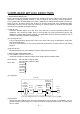
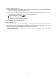
5. PARAMETERS 5.2.2 Analog monitor The servo status can be output to two channels in terms of voltage. The servo status can be monitored using an ammeter. (1) Setting Change the following digits of parameter No.17: Parameter No. 17 0 0 Analog monitor (MO1) output selection (Signal output to across MO1-LG) Analog monitor (MO2) output selection (Signal output to across MO2-LG) Parameters No.31 and 32 can be used to set the offset voltages to the analog output voltages.
5. PARAMETERS (2) Set content The servo amplifier is factory-set to output the servo motor speed to analog monitor 1 (MO1) and the torque to analog monitor (MO2). The setting can be changed as listed below by changing the parameter No.17 value: Refer to Appendix 2 for the measurement point. Setting 0 Output item Servo motor speed Description Setting 6 CCW direction 8[V] Max. speed Output item Droop pulses (Note1) ( 10V/128pulse) Description 10[V] 128[pulse] 0 Max.
Command pulse Command pulse frequency Droop pulse Position control Speed command Differential Servo Motor speed Speed control Current command Torque Current control 5 - 32 Encoder M Servo Motor Position feedback Current feedback PWM Current encoder Bus voltage 5.
5. PARAMETERS 5.2.3 Using forward/reverse rotation stroke end to change the stopping pattern The stopping pattern is factory-set to make a sudden stop when the forward/reverse rotation stroke end is made valid. A slow stop can be made by changing the parameter No. 22 value. Parameter No.22 Setting 0 (initial value) Stopping method Sudden stop Position control mode : Motor stops with droop pulses cleared. Speed control mode : Motor stops at deceleration time constant of zero.
5. PARAMETERS 5.2.5 Position smoothing By setting the position command acceleration/deceleration time constant (parameter No.7), you can run the servo motor smoothly in response to a sudden position command. The following diagrams show the operation patterns of the servo motor in response to a position command when you have set the position command acceleration/deceleration time constant. Choose the primary delay or linear acceleration/deceleration in parameter No. 55 according to the machine used.
6. DISPLAY AND OPERATION 6. DISPLAY AND OPERATION 6.1 Display flowchart Use the display (5-digit, 7-segment LED) on the front panel of the servo amplifier for status display, parameter setting, etc. Set the parameters before operation, diagnose an alarm, confirm external sequences, and/or confirm the operation status. Press the "MODE" "UP" or "DOWN" button once to move to the next screen. To refer to or set the expansion parameters, make them valid with parameter No. 19 (parameter write disable).
6. DISPLAY AND OPERATION 6.2 Status display The servo status during operation is shown on the 5-digit, 7-segment LED display. Press the "UP" or "DOWN" button to change display data as desired. When the required data is selected, the corresponding symbol appears. Press the "SET" button to display its data. At only power-on, however, data appears after the symbol of the status display selected in parameter No. 18 has been shown for 2[s].
6. DISPLAY AND OPERATION 6.2.2 Status display list The following table lists the servo statuses that may be shown: Refer to Appendix 2 for the measurement point. Name Symbol Unit Description Cumulative feedback pulses C pulse Servo motor speed r r/min Feedback pulses from the servo motor encoder are counted and displayed. The value in excess of 99999 is counted, bus since the servo amplifier display is five digits, it shows the lower five digits of the actual value.
6. DISPLAY AND OPERATION Display range Name Symbol Unit Description Within one-revolution position high Cy2 100 pulse The within one-revolution position is displayed in 100 pulse increments of the encoder. The value returns to 0 when it exceeds the maximum number of pulses. The value is incremented in the CCW direction of rotation.
6. DISPLAY AND OPERATION 6.3 Diagnostic mode Name Display Description Not ready. Indicates that the servo amplifier is being initialized or an alarm has occurred. Sequence Ready. Indicates that the servo was switched on after completion of initialization and the servo amplifier is ready to operate. External I/O signal display Indicates the ON-OFF states of the external I/O signals. The upper segments correspond to the input signals and the lower segments to the output signals.
6. DISPLAY AND OPERATION Name Display Description Motor series Press the "SET" button to show the motor series ID of the servo motor currently connected. For indication details, refer to the optional MELSERVO Servo Motor Instruction Manual. Motor type Press the "SET" button to show the motor type ID of the servo motor currently connected. For indication details, refer to the optional MELSERVO Servo Motor Instruction Manual.
6. DISPLAY AND OPERATION 6.4 Alarm mode The current alarm, past alarm history and parameter error are displayed. The lower 2 digits on the display indicate the alarm number that has occurred or the parameter number in error. Display examples are shown below. Name Display Description Indicates no occurrence of an alarm. Current alarm Indicates the occurrence of overvoltage (AL.33). Flickers at occurrence of the alarm. Indicates that the last alarm is overload 1 (AL.50).
6. DISPLAY AND OPERATION 6.5 Parameter mode The parameters whose abbreviations are marked* are made valid by changing the setting and then switching power off once and switching it on again. Refer to Section 5.1.2. (1) Operation example The following example shows the operation procedure performed after power-on to change the control mode (parameter No. 0) to the speed control mode. Using the "MODE" button, show the basic parameter screen. The parameter number is displayed.
6. DISPLAY AND OPERATION 6.6 External I/O signal display The ON/OFF states of the digital I/O signals connected to the servo amplifier can be confirmed. (1) Operation Call the display screen shown after power-on. Using the "MODE" button, show the diagnostic screen. Press UP once.
6. DISPLAY AND OPERATION (a) Control modes and I/O signals Connector (Note 2) Symbols of I/O signals in control modes Signal input/output (Note 1) I/O Pin No. P P/S S S/T T T/P Related parameter CR CR/SP1 SP1 SP1 SP1 SP1/CR No.43 to 48 OP OP OP /INP No.49 RD RD No.49 8 I 14 O OP OP OP 18 O INP INP/SA SA 19 O RD RD RD (Note 3) 4 O DO1 DO1 DO1 DO1 DO1 DO1 5 I SON SON SON SON SON SON 6 O TLC 7 I 8 I 9 I 14 CN1A CN1B SA/ RD No.
6.
6. DISPLAY AND OPERATION 6.7 Output signal (DO) forced output POINT When the servo system is used in a vertical lift application, turning on the electromagnetic brake interlock (MBR) after assigning it to pin CN1B-19 will release the electromagnetic brake, causing a drop. Take drop preventive measures on the machine side. The output signal can be forced on/off independently of the servo status. This function is used for output signal wiring check, etc.
6. DISPLAY AND OPERATION 6.8 Test operation mode CAUTION The test operation mode is designed to confirm servo operation and not to confirm machine operation. In this mode, do not use the servo motor with the machine. Always use the servo motor alone. If any operational fault has occurred, stop operation using the emergency stop (EMG) signal. POINT The test operation mode cannot be used in the absolute position detection system. Use it after choosing "Incremental system" in parameter No. 1.
6. DISPLAY AND OPERATION 6.8.2 Jog operation Jog operation can be performed when there is no command from the external command device. (1) Operation Connect EMG-SG to start jog operation and connect VDD-COM to use the internal power supply. Hold down the "UP" or "DOWN" button to run the servo motor. Release it to stop. When using the MR Configurator (servo configuration software), you can change the operation conditions.
6. DISPLAY AND OPERATION 6.8.3 Positioning operation POINT The MR Configurator (servo configuration software) is required to perform positioning operation. Positioning operation can be performed once when there is no command from the external command device. (1) Operation Connect EMG-SG to start positioning operation and connect VDD-COM to use the internal power supply.
6. DISPLAY AND OPERATION 6.8.4 Motor-less operation Without connecting the servo motor, you can provide output signals or monitor the status display as if the servo motor is running in response to external input signals. This operation can be used to check the sequence of a host programmable controller or the like. (1) Operation After turning off the signal across SON-SG, choose motor-less operation. After that, perform external operation as in ordinary operation.
7. GENERAL GAIN ADJUSTMENT 7. GENERAL GAIN ADJUSTMENT POINT For use in the torque control mode, you need not make gain adjustment. 7.1 Different adjustment methods 7.1.1 Adjustment on a single servo amplifier The gain adjustment in this section can be made on a single servo amplifier. For gain adjustment, first execute auto tuning mode 1. If you are not satisfied with the results, execute auto tuning mode 2, manual mode 1 and manual mode 2 in this order.
7. GENERAL GAIN ADJUSTMENT (2) Adjustment sequence and mode usage START Usage Interpolation made for 2 or more axes? Yes Interpolation mode No Operation Allows adjustment by merely changing the response level setting. First use this mode to make adjustment. Auto tuning mode 1 Operation Yes No OK? No OK? Yes Auto tuning mode 2 Operation Yes OK? Used when the conditions of auto tuning mode 1 are not met and the load inertia moment ratio could not be estimated properly, for example.
7. GENERAL GAIN ADJUSTMENT 7.2 Auto tuning 7.2.1 Auto tuning mode The servo amplifier has a real-time auto tuning function which estimates the machine characteristic (load inertia moment ratio) in real time and automatically sets the optimum gains according to that value. This function permits ease of gain adjustment of the servo amplifier. (1) Auto tuning mode 1 The servo amplifier is factory-set to the auto tuning mode 1.
7. GENERAL GAIN ADJUSTMENT 7.2.2 Auto tuning mode operation The block diagram of real-time auto tuning is shown below. Load inertia moment Automatic setting Command Encoder Control gains PG1,VG1 PG2,VG2,VIC Current control Servo motor Current feedback Set 0 or 1 to turn on. Gain table Switch Load inertia moment ratio estimation section Position/speed feedback Speed feedback Parameter No. 34 Load inertia moment ratio estimation value Parameter No.
7. GENERAL GAIN ADJUSTMENT 7.2.3 Adjustment procedure by auto tuning Since auto tuning is made valid before shipment from the factory, simply running the servo motor automatically sets the optimum gains that match the machine. Merely changing the response level setting value as required completes the adjustment. The adjustment procedure is as follows. Auto tuning adjustment Acceleration/deceleration repeated Yes Load inertia moment ratio estimation value stable? No Auto tuning conditions not satisfied.
7. GENERAL GAIN ADJUSTMENT 7.2.4 Response level setting in auto tuning mode Set the response (The first digit of parameter No.2) of the whole servo system. As the response level setting is increased, the trackability and settling time for a command decreases, but a too high response level will generate vibration. Hence, make setting until desired response is obtained within the vibrationfree range.
7. GENERAL GAIN ADJUSTMENT 7.3 Manual mode 1 (simple manual adjustment) If you are not satisfied with the adjustment of auto tuning, you can make simple manual adjustment with three parameters. 7.3.1 Operation of manual mode 1 In this mode, setting the three gains of position control gain 1 (PG1), speed control gain 2 (VG2) and speed integral compensation (VIC) automatically sets the other gains to the optimum values according to these gains.
7. GENERAL GAIN ADJUSTMENT (c)Adjustment description 1) Speed control gain 2 (parameter No. 37) This parameter determines the response level of the speed control loop. Increasing this value enhances response but a too high value will make the mechanical system liable to vibrate.
7. GENERAL GAIN ADJUSTMENT (c) Adjustment description 1) Position control gain 1 (parameter No. 6) This parameter determines the response level of the position control loop. Increasing position control gain 1 improves trackability to a position command but a too high value will make overshooting liable to occur at the time of settling.
7. GENERAL GAIN ADJUSTMENT 7.4 Interpolation mode The interpolation mode is used to match the position control gains of the axes when performing the interpolation operation of servo motors of two or more axes for an X-Y table or the like. In this mode, the position control gain 2 and speed control gain 2 which determine command trackability are set manually and the other parameter for gain adjustment are set automatically.
7. GENERAL GAIN ADJUSTMENT 7.5 Differences in auto tuning between MELSERVO-J2 and MELSERVO-J2-Super 7.5.1 Response level setting To meet higher response demands, the MELSERVO-J2-Super series has been changed in response level setting range from the MELSERVO-J2 series. The following table lists comparison of the response level setting. Parameter No.
7.
8. SPECIAL ADJUSTMENT FUNCTIONS 8. SPECIAL ADJUSTMENT FUNCTIONS POINT The functions given in this chapter need not be used generally. Use them if you are not satisfied with the machine status after making adjustment in the methods in Chapter 7. If a mechanical system has a natural resonance point, increasing the servo system response level may cause the mechanical system to produce resonance (vibration or unusual noise) at that resonance frequency.
8. SPECIAL ADJUSTMENT FUNCTIONS You can use the machine resonance suppression filter 1 (parameter No. 58) and machine resonance suppression filter 2 (parameter No. 59) to suppress the vibration of two resonance frequencies. Note that if adaptive vibration suppression control is made valid, the machine resonance suppression filter 1 (parameter No. 58) is made invalid. Machine resonance point Mechanical system response level Frequency Notch depth Frequency Parameter No. 58 Parameter No.
8. SPECIAL ADJUSTMENT FUNCTIONS POINT If the frequency of machine resonance is unknown, decrease the notch frequency from higher to lower ones in order. The optimum notch frequency is set at the point where vibration is minimal. A deeper notch has a higher effect on machine resonance suppression but increases a phase delay and may increase vibration. The machine characteristic can be grasped beforehand by the machine analyzer on the MR Configurator (servo configuration software).
8. SPECIAL ADJUSTMENT FUNCTIONS (2) Parameters The operation of adaptive vibration suppression control selection (parameter No.60). Parameter No. 60 Adaptive vibration suppression control selection Choosing "valid" or "held" in adaptive vibration suppression control selection makes the machine resonance suppression filter 1 (parameter No. 58) invalid. 0: Invalid 1: Valid Machine resonance frequency is always detected to generate the filter in response to resonance, suppressing machine vibration.
8. SPECIAL ADJUSTMENT FUNCTIONS 8.5 Gain changing function This function can change the gains. You can change between gains during rotation and gains during stop or can use an external signal to change gains during operation. 8.5.1 Applications This function is used when: (1) You want to increase the gains during servo lock but decrease the gains to reduce noise during rotation. (2) You want to increase the gains during settling to shorten the stop settling time.
8. SPECIAL ADJUSTMENT FUNCTIONS 8.5.3 Parameters When using the gain changing function, always set " 4 " in parameter No.2 (auto tuning) to choose the manual mode of the gain adjustment modes. The gain changing function cannot be used in the auto tuning mode. Parameter Abbrevi No. ation Name Unit Description Position and speed gains of a model used to set the response level to a command. Always valid.
8. SPECIAL ADJUSTMENT FUNCTIONS (1) Parameters No. 6, 34 to 38 These parameters are the same as in ordinary manual adjustment. Gain changing allows the values of ratio of load inertia moment to servo motor inertia moment, position control gain 2, speed control gain 2 and speed integral compensation to be changed. (2) Ratio of load inertia moment to servo motor inertia moment 2 (GD2B: parameter No. 61) Set the ratio of load inertia moment to servo motor inertia moment after changing.
8. SPECIAL ADJUSTMENT FUNCTIONS 8.5.4 Gain changing operation This operation will be described by way of setting examples. (1) When you choose changing by external input (a) Setting Parameter No. Abbreviation Name Setting Unit 6 PG1 Position control gain 1 100 rad/s 36 VG1 Speed control gain 1 1000 rad/s 34 GD2 Ratio of load inertia moment to servo motor inertia moment 4 0.
8. SPECIAL ADJUSTMENT FUNCTIONS (2) When you choose changing by droop pulses (a) Setting Parameter No. Abbreviation Setting Unit 6 PG1 Position control gain 1 Name 100 rad/s 36 VG1 Speed control gain 1 1000 rad/s 34 GD2 Ratio of load inertia moment to servo motor inertia moment 40 0.1 times 35 PG2 Position control gain 2 120 rad/s 37 VG2 Speed control gain 2 3000 rad/s 38 VIC Speed integral compensation 20 ms 100 0.
8.
9. INSPECTION 9. INSPECTION WARNING Before starting maintenance and/or inspection, make sure that the charge lamp is off more than 15 minutes after power-off. Then, confirm that the voltage is safe in the tester or the like. Otherwise, you may get an electric shock. Any person who is involved in inspection should be fully competent to do the work. Otherwise, you may get an electric shock. For repair and parts replacement, contact your safes representative.
9.
10. TROUBLESHOOTING 10. TROUBLESHOOTING 10.1 Trouble at start-up CAUTION Excessive adjustment or change of parameter setting must not be made as it will make operation instable. POINT Using the MR Configurator (servo configuration software), you can refer to unrotated servo motor reasons, etc. The following faults may occur at start-up. If any of such faults occurs, take the corresponding action. 10.1.1 Position control mode (1) Troubleshooting No.
10. TROUBLESHOOTING No. 4 5 Start-up sequence Gain adjustment Cyclic operation Possible cause Reference Rotation ripples (speed fluctuations) are large at low speed. Fault Make gain adjustment in the Gain adjustment fault following procedure: 1. Increase the auto tuning response level. 2. Repeat acceleration and deceleration several times to complete auto tuning. Investigation Chapter 7 Large load inertia moment causes the servo motor shaft to oscillate side to side.
10. TROUBLESHOOTING (2) How to find the cause of position shift Positioning unit Servo amplifier (a) Output pulse counter Electronic gear (parameters No.
10. TROUBLESHOOTING 10.1.2 Speed control mode No. 1 2 3 4 Start-up sequence Power on Fault LED is not lit. LED flickers. Investigation Possible cause Reference 1. Power supply voltage fault Not improved if connectors CN1A, CN1B, CN2 and CN3 2. Servo amplifier is faulty. are disconnected. Improved when connectors CN1A and CN1B are disconnected. Power supply of CN1 cabling is shorted. Improved when connector CN2 is disconnected. 1. Power supply of encoder cabling is shorted. 2. Encoder is faulty.
10. TROUBLESHOOTING 10.1.3 Torque control mode No. 1 2 3 Start-up sequence Power on Fault LED is not lit. LED flickers. Investigation Possible cause Reference 1. Power supply voltage fault Not improved if connectors CN1A, CN1B, CN2 and CN3 2. Servo amplifier is faulty. are disconnected. Improved when connectors CN1A and CN1B are disconnected. Power supply of CN1 cabling is shorted. Improved when connector CN2 is disconnected. 1. Power supply of encoder cabling is shorted. 2. Encoder is faulty.
10. TROUBLESHOOTING 10.2 When alarm or warning has occurred POINT Configure up a circuit which will detect the trouble (ALM) and turn off the servo-on (SON) at occurrence of an alarm. 10.2.1 Alarms and warning list When a fault occurs during operation, the corresponding alarm or warning is displayed. If any alarm or warning has occurred, refer to Section 10.2.2 or 10.2.3 and take the appropriate action. When an alarm occurs, ALM turns off. Set " 1" in parameter No.
10. TROUBLESHOOTING 10.2.2 Remedies for alarms CAUTION When any alarm has occurred, eliminate its cause, ensure safety, then reset the alarm, and restart operation. Otherwise, injury may occur. If an absolute position erase (AL.25) occurred, always make home position setting again. Otherwise, misoperation may occur. As soon as an alarm occurs, turn off Servo-on (SON) and power off the main circuit.
10. TROUBLESHOOTING Display Name Definition AL.15 Memory error 2 EEP-ROM fault Cause Action 1. Faulty parts in the servo amplifier Change the servo amplifier. Checking method Alarm (AL.15) occurs if power is switched on after disconnection of all cables but the control circuit power supply cables. AL.16 AL.17 AL.19 AL.1A AL.20 AL.24 2. The number of write times to EEPROM exceeded 100,000. Encoder error 1 Communication 1. Encoder connector (CN2) error occurred disconnected. between encoder 2.
10. TROUBLESHOOTING Display Name AL.25 Absolute position erase AL.30 Regenerative alarm Definition Absolute position data in error Cause Action 1. Reduced voltage of super capacitor After leaving the alarm occurring for a few in encoder minutes, switch power off, then on again. Always make home position setting again. Change battery. 2. Battery voltage low 3. Battery cable or battery is faulty. Always make home position setting again. After leaving the alarm occurring for a few Power was switched 4.
10. TROUBLESHOOTING Display Name AL.32 Overcurrent AL.33 AL.35 AL.37 Overvoltage Definition Cause Current that flew is 1. Short occurred in servo amplifier higher than the output phases U, V and W. permissible current 2. Transistor (IPM) of the servo of the servo amplifier faulty. amplifier. Checking method Alarm (AL.32) occurs if power is switched on after U,V and W are disconnected. Action Correct the wiring. 3. Ground fault occurred in servo amplifier output phases U, V and W. 4.
10. TROUBLESHOOTING Display Name Definition AL.45 Main circuit Main circuit device device overheat overheat AL.46 Servo motor overheat Servo motor temperature rise actuated the thermal sensor. AL.50 Overload 1 Load exceeded overload protection characteristic of servo amplifier. Cause Action 1. Servo amplifier faulty. Change the servo amplifier. 2. The power supply was turned on The drive method is reviewed. and off continuously by overloaded status. 3. Air cooling fan of servo amplifier 1.
10. TROUBLESHOOTING Display Name Definition AL.52 Error excessive The difference (Note) between the model position and the actual servomotor position exceeds 2.5 rotations. (Refer to the function block diagram in Section 1.2.) Cause 1. Acceleration/deceleration time constant is too small. 2. Torque limit value (parameter No.28) is too small. 3. Motor cannot be started due to torque shortage caused by power supply voltage drop. 4. Position control gain 1 (parameter No.6) value is small. 5.
10. TROUBLESHOOTING 10.2.3 Remedies for warnings CAUTION If an absolute position counter warning (AL.E3) occurred, always make home position setting again. Otherwise, misoperation may occur. POINT When any of the following alarms has occurred, do not resume operation by switching power of the servo amplifier OFF/ON repeatedly. The servo amplifier and servo motor may become faulty.
10. TROUBLESHOOTING Display Name Definition AL.E5 ABS time-out warning Action Contact the program. 2. Reverse rotation start (ST2) Limiting Connect properly. torque (TLC) improper wiring AL.E6 Servo emergency EMG is off. stop warning AL.E9 Main circuit off warning Cause 1. PC lader program wrong. External emergency stop was made valid. Ensure safety and deactivate (EMG was turned off.) emergency stop. Switch on main circuit power. Servo-on (SON) was switched on with main circuit power off. AL.
11. OUTLINE DIMENSION DRAWINGS 11. OUTLINE DIMENSION DRAWINGS 11.1 Servo amplifiers (1) MR-J2S-10A to MR-J2S-60A MR-J2S-10A1 to MR-J2S-40A1 [Unit: mm] B 6 (0.24) ([Unit: in]) 135 (5.32) Terminal layout (Terminal cover open) (0.79) 6 ( 0.24) mounting hole Approx.70 (2.76) Approx. 20 A MITSUBISHI MITSUBISHI OPEN C N 1 A C N 1 B C N 2 E N C C N 3 TE1 C N 1 B C N 2 C N 3 E N C ) L1 L2 L3 (Note) 6 (0.24) Approx.7 (0.28) Name plate C N 1 A ( 168 (6.61) 156 (6.
11. OUTLINE DIMENSION DRAWINGS (2) MR-J2S-70A MR-J2S-100A [Unit: mm] 70(2.76) Approx.70(2.76) ([Unit: in]) 190(7.48) Approx. 20 6 (0.24) 22 (0.87) Terminal layout (Terminal cover open) (0.79) 6 ( 0.24) mounting hole MITSUBISHI MITSUBISHI 6(0.24) Approx.7 (0.28) 168(6.61) 156(6.14) OPEN OPEN C N 1 A C N 1 B C N 2 E N C C N 3 L1 L2 L3 U V W Name plate PE terminal 6(0.24) 22 42 (0.87) (1.65) TE2 TE1 6(0.24) 6(0.24) Mass [kg]([lb]) Servo amplifier MR-J2S-70A 1.7 (3.
11. OUTLINE DIMENSION DRAWINGS (3) MR-J2S-200A MR-J2S-350A [Unit: mm] 6 (0.24) 6 ( 0.24) mounting hole ([Unit: in]) Approx.70 (2.76) 90(3.54) 78(3.07) 6 (0.24) 195(7.68) Terminal layout MITSUBISHI 168(6.61) 156(6.14) MITSUBISHI TE2 TE1 PE terminal Fan air orientation Mass [kg]([lb]) Servo amplifier MR-J2S-200A 2.0 (4.41) MR-J2S-350A Terminal signal layout PE terminals TE1 L1 L2 L3 U V W Terminal screw: M4 Tightening torque: 1.2 [N m] (10.
11. OUTLINE DIMENSION DRAWINGS (4) MR-J2S-500A [Unit: mm] ([Unit: in]) OPEN (0.79) Approx. (0.24) 130(5.12) (0.24) 70 6 6 (2.76) 118(4.65) Approx.20 7.5 (0.5) 2- 6( 0.24) mounting hole 200(7.87) (0.19) 5 Terminal layout MITSUBISHI MITSUBISHI 235(9.25) 250(9.84) OPEN C N 1 B C N 1 A C N 1 B C N 2 C N 3 C N 2 C N 3 TE2 N.P. N.P. Fan 7.5 (0.5) OPEN TE1 C N 1 A Fan 6(0.24) Fan air orientation Servo amplifier Mass [kg]([lb]) MR-J2S-500A 4.9(10.
11. OUTLINE DIMENSION DRAWINGS (5) MR-J2S-700A 2- 6( 0.24) mounting hole (0.39) Approx.20 200(7.87) Approx.70 138(5.43) 62 10 (2.76) 180(7.09) 160(6.23) (0.79) 7.5 (0.5) (0.39) 10 (2.44) [Unit: mm] ([Unit: in]) 6(0.24) Terminal layout MITSUBISHI MITSUBISHI OPEN OPEN C N 1 A C N 1 B C N 1 A C N 1 B C N 2 C N 3 C N 2 C N 3 350(13.8) 335(13.2) TE2 OPEN TE1 Fan 7.5 (0.5) 6 (0.24) Fan air orientation Servo amplifier Mass [kg]([lb]) MR-J2S-700A 7.2(15.
11. OUTLINE DIMENSION DRAWINGS (6) MR-J2S-11KA 15KA 12(0.47) [Unit: mm] ([Unit: in]) 2- 12( 0.47) mounting hole Approx. 75 (2.95) Fan air orientation Fan MITSUBISHI C N 3 C N 1 A C N 1 B 400(15.75) 376(14.8) CN4 TE2 CN2 CON2 CHARGE Mass [kg]([lb]) MR-J2S-11KA 15(33.1) MR-J2S-15KA 16(35.3) 260(10.24) 12(0.47) 3.9(0.15) Servo amplifier (0.47) 12(0.47) 236(9.29) 260(10.24) (0.
11. OUTLINE DIMENSION DRAWINGS 12(0.47) (7) MR-J2S-22KA 2- 12( 0.47) mounting hole Approx. 75 (2.95) [Unit: mm] ([Unit: in]) Fan air orientation Fan MITSUBISHI C N 3 C N 1 A C N 1 B 400(15.75) 376(14.8) CN4 TE2 CON2 CN2 CHARGE 12(0.47) 326(12.84) 350(13.78) 12(0.47) 3.9(0.15) 260(0.24) (0.47)12 12 (0.47) TE1 Servo amplifier Mass [kg]([lb]) MR-J2S-22KA 20(44.1) Terminal signal layout TE1 PE terminal L1 L2 L3 U V W P1 P C N Terminal screw : M8 Tightening torque : 6.
11. OUTLINE DIMENSION DRAWINGS 11.2 Connectors (1) Servo amplifier side <3M> (a) Soldered type Model Connector Shell kit : 10120-3000VE : 10320-52F0-008 [Unit: mm] ([Unit: in]) 10.0 (0.39) 12.0(0.47) 14.0 (0.55) Logo, etc. are indicated here. 39.0(1.54) 23.8(0.94) A B 12.7 (0.50) Connector Shell kit 10120-3000VE 10320-52F0-008 Variable dimensions A B 22.0(0.87) 33.3(1.31) (b) Threaded type [Unit: mm] ([Unit: in]) 10.0 12.0(0.47) 39.0(1.54) (0.22)5.7 23.8(0.94) 22.0(0.87) 33.3 (1.
11. OUTLINE DIMENSION DRAWINGS (c) Insulation displacement type Model Connector Shell kit : 10120-6000EL : 10320-3210-000 [Unit: mm] ([Unit: in]) 11.5 (0.45) 6.7 ( 0.26) 2- 0.5 (0.02) Logo, etc. are indicated here. 42.0(1.65) 33.0(1.30) 20.9(0.82) 29.7 (1.17) (2) Bus cable connector [Unit: mm] ([Unit: in]) PCR-LS20LA1 PCR-LS20LA1W 13.0 10.4(0.41) 14.2(0.56) 23.0(0.91) (0.04)1 12.2 1(0.04) (0.48) 20.6 (0.81) (0.51) HONDA HONDA 27.4(1.08) 32.0(0.91) 27.4(1.
11. OUTLINE DIMENSION DRAWINGS (3) Communication cable connector [Unit: mm] ([Unit: in]) B A Fitting fixing screw G E (max. diameter of cable used) F C D Type DE-C1-J6-S6 A 1 B 1 C 0.25 D 1 34.5(1.36) 19(0.75) 24.99(0.98) 33(1.30) 11 - 10 E 6(0.24) F Reference G 18(0.
12. CHARACTERISTICS 12. CHARACTERISTICS 12.1 Overload protection characteristics An electronic thermal relay is built in the servo amplifier to protect the servo motor and servo amplifier from overloads. Overload 1 alarm (AL.50) occurs if overload operation performed is above the electronic thermal relay protection curve shown in any of Figs 12.1. Overload 2 alarm (AL.51) occurs if the maximum current flew continuously for several seconds due to machine collision, etc.
12. CHARACTERISTICS 12.2 Power supply equipment capacity and generated loss (1) Amount of heat generated by the servo amplifier Table 12.1 indicates servo amplifiers' power supply capacities and losses generated under rated load. For thermal design of an enclosure, use the values in Table 12.1 in consideration for the worst operating conditions. The actual amount of generated heat will be intermediate between values at rated torque and servo off according to the duty used during operation.
12. CHARACTERISTICS Servo amplifier MR-J2S-500A MR-J2S-700A MR-J2S-11KA MR-J2S-15KA MR-J2S-22KA Servo motor (Note 1) Power supply capacity[kVA] (Note 2) Servo amplifier-generated heat[W] Area required for heat dissipation At rated torque With servo off [m2] [ft2] HC-SFS502 7.5 195 25 3.9 42.0 HC-RFS353 5.5 135 25 2.7 29.1 HC-RFS503 7.5 195 25 3.9 42.0 HC-UFS352 5.5 195 25 3.9 42.0 HC-UFS502 7.5 195 25 3.9 42.0 HC-LFS302 4.5 120 25 2.4 25.8 HA-LFS502 7.
12. CHARACTERISTICS (2) Heat dissipation area for enclosed servo amplifier The enclosed control box (hereafter called the control box) which will contain the servo amplifier should be designed to ensure that its temperature rise is within 10 at the ambient temperature of 40 . (With a 5 (41 ) safety margin, the system should operate within a maximum 55 (131 ) limit.) The necessary enclosure heat dissipation area can be calculated by Equation 12.1: P .........................................................
12. CHARACTERISTICS 12.3 Dynamic brake characteristics Fig. 12.6 shows the pattern in which the servo motor comes to a stop when the dynamic brake is operated. Use Equation 12.2 to calculate an approximate coasting distance to a stop. The dynamic brake time constant varies with the servo motor and machine operation speeds. (Refer to Fig. 12.7. Please contact us for the servo motor not indicated.) Emergency stop(EMG) ON OFF Time constant V0 Machine speed Time te Fig. 12.
12. CHARACTERISTICS 0.04 0.045 0.04 0.035 121 0.03 Time constant [s] Time constant [s] 0.035 201 0.025 0.02 301 0.015 0.01 0 0 50 500 Speed [r/min] 352 0.025 0.02 1000 c. HC-SFS1000r/min series 202 52 502 0.015 0.01 0.005 0 0 81 0.005 702 0.03 102 152 500 1000 1500 Speed [r/min] 2000 d. HC-SFS2000r/min series 0.1 Time constant [s] 203 53 0.08 0.06 353 0.04 103 0.02 0 0 50 153 500 1000 1500 2000 2500 3000 Speed [r/min] 0.018 0.016 0.014 0.012 0.01 0.008 0.
12. CHARACTERISTICS Use the dynamic brake at the load inertia moment indicated in the following table. If the load inertia moment is higher than this value, the built-in dynamic brake may burn. If there is a possibility that the load inertia moment may exceed the value, contact Mitsubishi. Servo amplifier Load inertia moment ratio [times] MR-J2S-10A to MR-J2S-200A MR-J2S-10A1 to MR-J2S-40A1 30 MR-J2S-350A 16 MR-J2S-500A MR-J2S-700A 15 MR-J2S-11KA to MR-J2S-22KA (Note) 30 Note.
12. CHARACTERISTICS 12.5 Inrush currents at power-on of main circuit and control circuit The following table indicates the inrush currents (reference value) that will flow when the maximum permissible voltage (253VAC) is applied at the power supply capacity of 2500kVA and the wiring length of 1m. Servo Amplifier Inrush Currents (A0-p) Main circuit power supply (L1, L2, L3) MR-J2S-10A 20A 30A (Attenuated to approx. 5A in 10ms) MR-J2S-40A 60A 30A (Attenuated to approx.
13. OPTIONS AND AUXILIARY EQUIPMENT 13. OPTIONS AND AUXILIARY EQUIPMENT WARNING Before connecting any option or auxiliary equipment, make sure that the charge lamp is off more than 15 minutes after power-off, then confirm the voltage with a tester or the like. Otherwise, you may get an electric shock. CAUTION Use the specified auxiliary equipment and options. Unspecified ones may lead to a fault or fire. 13.1 Options 13.1.
13. OPTIONS AND AUXILIARY EQUIPMENT Unbalance torque Servo motor speed (b) To make selection according to regenerative energy Use the following method when regeneration occurs continuously in vertical motion applications or when it is desired to make an in-depth selection of the regenerative brake option: a. Regenerative energy calculation Use the following table to calculate the regenerative energy.
13. OPTIONS AND AUXILIARY EQUIPMENT Subtract the capacitor charging from the result of multiplying the sum total of regenerative energies by the inverse efficiency to calculate the energy consumed by the regenerative brake option. ER [J] Es Ec Calculate the power consumption of the regenerative brake option on the basis of single-cycle operation period tf [s] to select the necessary regenerative brake option. PR [W] ER/tf .....................................................................................
13. OPTIONS AND AUXILIARY EQUIPMENT (4) Connection of the regenerative brake option POINT When using the MR-RB50 and MR-RB51, cooling by a fan is required. Please obtain a cooling fan at your discretion. The regenerative brake option will cause a temperature rise of +100 (+212 ) degrees relative to the ambient temperature. Fully examine heat dissipation, installation position, used cables, etc. before installing the option.
13. OPTIONS AND AUXILIARY EQUIPMENT (b) MR-J2S-500A MR-J2S-700A Always remove the wiring (across P-C) of the servo amplifier built-in regenerative brake resistor and fit the regenerative brake option across P-C. The G3 and G4 terminals act as a thermal sensor. G3-G4 are opened when the regenerative brake option overheats abnormally. Servo amplifier P C Always remove wiring (across P-C) of servo amplifier built-in regenerative brake resistor. Regenerative brake option P C (Note 2) G3 G4 5m(16.
13. OPTIONS AND AUXILIARY EQUIPMENT For the MR-RB50 MR-RB51 install the cooling fan as shown. [Unit : mm(in)] Fan installation screw hole dimensions 2-M3 screw hole Top (for fan installation) Depth 10 or less (Screw hole already machined) 82.5 Terminal block 133 (5.24) Thermal relay (3.25) Fan Bottom 82.5 40 (1.58) (3.
13. OPTIONS AND AUXILIARY EQUIPMENT (d) MR-J2S-11KA-PX to MR-J2S-22KA-PX (when using the regenerative brake option) The MR-J2S-11KA-PX to MR-J2S-22KA-PX servo amplifiers are not supplied with regenerative brake resistors. When using any of these servo amplifiers, always use the MR-RB65, 66 or 67 regenerative brake option. The MR-RB65, 66 and 67 are regenerative brake options that have encased the GRZG400-2Ω, GRZG400-1Ω and GRZG400-0.8Ω, respectively.
13. OPTIONS AND AUXILIARY EQUIPMENT (5) Outline drawing (a) MR-RB032 MR-RB12 [Unit: mm (in)] LA 12 (0.47) 6 (0.23) 6 (0.24) mounting hole LB 144 (5.67) TE1 Terminal block 5 (0.20) G3 G4 P C 6 (0.23) 12 (0.47) G3 G4 P C 6 (0.23) TE1 168 (6.61) 156 (6.14) MR-RB Terminal screw: M3 Tightening torque: 0.5 to 0.6 [N m](4 to 5 [lb in]) Mounting screw Screw size: M5 Tightening torque: 3.2 [N m](28.32 [lb in]) 1.6 (0.06) 20 (0.79) LD LC Variable dimensions LA LB LC LD 30 15 119 99 MR-RB032 (1.
13. OPTIONS AND AUXILIARY EQUIPMENT (c) MR-RB50 MR-RB51 82.5 (3.25) 133 (5.24) 12.5 (0.49) P C Terminal screw: M4 G3 Tightening torque: 1.2 [N m](10.6 [lb in]) G4 G4 G3 C P 14 slot 350 (13.78) 7 Mounting screw Screw : M6 Tightening torque: 5.4 [N m](47.79 [lb in]) Wind blows in the arrow direction. 162.5(6.39) 82.5 49 (1.93) (3.25) [Unit: mm (in)] Terminal block 162.5 (6.39) Fan mounting screw (2-M3 screw) On opposite side Regenerative brake option Mass [kg] (lb) MR-RB50 5.6 (12.3) 2.
13. OPTIONS AND AUXILIARY EQUIPMENT 13.1.2 Brake unit POINT The brake unit and resistor unit of other than 200V class are not applicable to the servo amplifier. The brake unit and resistor unit of the same capacity must be combined. The units of different capacities may result in damage. The brake unit and resistor unit must be installed on a vertical surface in the vertical direction. If they are installed in the horizontal direction or on a horizontal surface, a heat dissipation effect reduces.
13. OPTIONS AND AUXILIARY EQUIPMENT The cables between the servo amplifier and brake unit and between the resistor unit and brake unit should be as short as possible. The cables longer than 5m(16.404ft) should be twisted. If twisted, the cables must not be longer than 10m(32.808ft). The cable size should be equal to or larger than the recommended size. See the brake unit instruction manual. You cannot connect one set of brake unit to two servo amplifiers or two sets of brake units to one servo amplifier.
13. OPTIONS AND AUXILIARY EQUIPMENT (b) Resistor unit (FR-BR) EE (E) 204 Eye bolt (8.031) 33 (1.299) C 5 (0.197) AA 5 (0.197) FR-BR-55K Two eye bolts are provided (as shown below). 40 (1.575) EE (E) (Note) (F) Control circuit terminals Main circuit terminals BB 3 (0.118) B 5 (0.197) BA 1 (0.039) K 2- D (F) [Unit : mm(in)] A 5 (0.197) Note. Ventilation ports are provided in both side faces and top face. The bottom face is open. Resistor Unit Model A AA C D E EE K F Approx.
13. OPTIONS AND AUXILIARY EQUIPMENT (2) Connection example Servo amplifier L11 L21 NFB (Note3)Power factor improving reactor FR-BAL MC L1 Power supply 3-phase 200V or 230VAC L2 L3 VDD SG COM EMG RA2 ALM SON (Note2) N N/ C P/ P P1 (Note4) 5m(16.4ft) or less RDY Ready A SE RDY output R/L1 S/L2 B B C C Alarm output T/L3 RX R SX S (Note 1) Phase detection terminals TX T Power regeneration converter FR-RC FR-RC B C RA2 EMG Operation ready ON OFF MC MC SK Note 1.
13. OPTIONS AND AUXILIARY EQUIPMENT (3) Outside dimensions of the power regeneration converters [Unit : mm(in)] Mounting foot (removable) Mounting foot movable E 2- D hole Rating plate Display panel window BA B Front cover Cooling fan K F EE D AA C A Heat generation area outside mounting dimension Power regeneration converter A AA B BA C D E EE K F Approx. Mass [kg(Ib)] FR-RC-15K 270 200 450 432 195 (10.630) (7.874) (17.717) (17.008) (7.677) 10 (0.394) 10 (0.394) 8 (0.315) 3.
13. OPTIONS AND AUXILIARY EQUIPMENT 13.1.4 External dynamic brake (1) Selection of dynamic brake The dynamic brake is designed to bring the servo motor to a sudden stop when a power failure occurs or the protective circuit is activated, and is built in the 7kW or less servo amplifier. Since it is not built " in the parameter in the 11kW or more servo amplifier, purchase it separately if required. Set " 1 No. 1.
13. OPTIONS AND AUXILIARY EQUIPMENT Coasting Servo motor rotation Coasting Dynamic brake Dynamic brake Present Alarm Absent ON Base OFF ON RA1 OFF Dynamic brake Invalid Valid Short emergency stop (EMG) Open a. Timing chart at alarm occurrence b.
13. OPTIONS AND AUXILIARY EQUIPMENT (3) Outline dimension drawing [Unit: mm] ([Unit: in]) D (0.2)5 100(3.94) E B A E 5 (0.2) G D 2.3(0.09) F C Terminal block E a (GND) U b 13 14 V W Screw : M4 Tightening torque : 1.2 [N m](10.6 [lb in])] Screw : M3.5 Tightening torque : 0.8 [N m](7 [lb in])] Dynamic brake A B C D E F G Mass [kg]([Ib]) Connection wire [mm2] DBU-11K 200 (7.87) 190 (7.48) 140 (5.51) 20 (0.79) 5 (0.2) 170 (6.69) 163.5 (6.44) 2 (4.41) 5.
13. OPTIONS AND AUXILIARY EQUIPMENT 13.1.5 Cables and connectors (1) Cable make-up The following cables are used for connection with the servo motor and other models. Those indicated by broken lines in the figure are not options.
13. OPTIONS AND AUXILIARY EQUIPMENT No. Product Model Description Connector: 10120-3000VE Shell kit: 10320-52F0-008 (3M or equivalent) Application Standard Housing : 1-172161-9 flexing life Connector pin : 170359-1 (Tyco Electronics or equivalent) IP20 Cable clamp : MTI-0002 (Toa Electric Industry) 1) Standard encoder MR-JCCBL M-L cable Refer to (2) in this section.
13. OPTIONS AND AUXILIARY EQUIPMENT No. 9) 10) 11) Product 16) 17) 18) 19) Junction terminal block cable MR-J2TBL M Refer to Section13.1.6. Connector: HIF3BA-20D-2.54R (Hirose Electric) Junction terminal block MR-TB20 Refer to Section 13.1.6. Bus cable MR-J2HBUS M Refer to section13.1.7. Connector: 10120-6000EL Shell kit: 10320-3210-000 (3M or equivalent) Maintenance junction card MR-J2CN3TM Refer to Section 13.1.7.
13. OPTIONS AND AUXILIARY EQUIPMENT (2) Encoder cable CAUTION If you have fabricated the encoder cable, connect it correctly. Otherwise, misoperation or explosion may occur. POINT The encoder cable is not oil resistant. Refer to Section 12.4 for the flexing life of the encoder cable. When the encoder cable is used, the sum of the resistance values of the cable used for P5 and the cable used for LG should be within 2.4 .
13.
13. OPTIONS AND AUXILIARY EQUIPMENT (b) MR-JHSCBL M-L MR-JHSCBL M-H MR-ENCBL M-H These encoder cables are used with the HC-SFS HC-RFS HC-UFS2000r/min series servo motors. 1) Model explanation Model: MR-JHSCBL MSymbol Specifications L Standard flexing life H Long flexing life Symbol Cable length [m(ft)] 2 5 10 20 30 40 50 2 (6.56) 5 (16.4) 10 (32.8) 20 (65.6) 30 (98.4) 40 (131.2) 50 (164.0) Note. MR-JHSCBL M-L has no 40(131.2) and 50m(164.0ft) sizes.
13.
13. OPTIONS AND AUXILIARY EQUIPMENT (3) Communication cable POINT This cable may not be used with some personal computers. After fully examining the signals of the RS-232C connector, refer to this section and fabricate the cable.
13. OPTIONS AND AUXILIARY EQUIPMENT 13.1.6 Junction terminal block (MR-TB20) POINT When using the junction terminal block, you cannot use SG of CN1A-20 and CN1B-20. Use SG of CN1A-10 and CN1B-10. (1) How to use the junction terminal block Always use the junction terminal block (MR-TB20) with the junction terminal block cable (MRJ2TBL M) as a set.
13. OPTIONS AND AUXILIARY EQUIPMENT (4) Junction terminal block cable (MR-J2TBL M) Model : MR-J2TBL M Symbol Cable length[m(ft)] 05 0.5 (1.64) 1 1 (3.28) Junction terminal block side connector (Hirose Electric) HIF3BA-20D-2.54R (connector) Servo amplifier side (CN1A CN1B) connector (3M) 10120-6000EL (connector) 10320-3210-000 (shell kit) (Note) Symbol Junction terminal Position control mode Speed control mode Torque control mode block terminal No.
13. OPTIONS AND AUXILIARY EQUIPMENT 13.1.7 Maintenance junction card (MR-J2CN3TM) POINT Cannot be used with the MR-J2S-11KA to MR-J2S-22KA. (1) Usage The maintenance junction card (MR-J2CN3TM) is designed for use when a personal computer and analog monitor outputs are used at the same time.
13. OPTIONS AND AUXILIARY EQUIPMENT (4) Bus cable (MR-J2HBUS M) Model: MR-J2HBUS M Symbol Cable length [m(ft)] 05 1 5 0.5 (1.64) 1 (3.28) 5 (16.4) MR-J2HBUS05M MR-J2HBUS1M MR-J2HBUS5M 10120-6000EL (connector) 10320-3210-000 (shell kit) 10120-6000EL (connector) 10320-3210-000 (shell kit) 1 11 2 12 3 13 4 14 5 15 6 16 7 17 8 18 9 19 10 20 1 11 2 12 3 13 4 14 5 15 6 16 7 17 8 18 9 19 10 20 Plate Plate 13.1.
13. OPTIONS AND AUXILIARY EQUIPMENT 13.1.9 MR Configurator (Servo configurations software) The MR Configurator (servo configuration software MRZJW3-SETUP151E) uses the communication function of the servo amplifier to perform parameter setting changes, graph display, test operation, etc. on a personal computer. (1) Specifications Item Description Communication signal Baudrate [bps] Conforms to RS-232C.
13. OPTIONS AND AUXILIARY EQUIPMENT (b) Configuration diagram 1) When using RS-232C Servo amplifier Personal computer Communication cable CN3 CN2 Servo motor To RS-232C connector 2) When using RS-422 You can make multidrop connection of up to 32 axes. Servo amplifier Personal computer RS-232C/RS-422 (Note) converter Communication cable CN3 CN2 Servo motor (Axis 1) To RS-232C connector Servo amplifier CN3 CN2 Servo motor (Axis 2) Servo amplifier CN3 CN2 (Axis 32) Note.
13. OPTIONS AND AUXILIARY EQUIPMENT 13.1.10 Power regeneration common converter POINT For details of the power regeneration common converter FR-CV, refer to the FR-CV Installation Guide (IB(NA)0600075). Do not supply power to the main circuit power supply terminals (L1, L2, L3) of the servo amplifier. Doing so will fail the servo amplifier and FR-CV. Connect the DC power supply between the FR-CV and servo amplifier with correct polarity.
13.
13. OPTIONS AND AUXILIARY EQUIPMENT 2) Grounding For grounding, use the wire of the size equal to or greater than that indicated in the following table, and make it as short as possible. Grounding wire size [mm2] Power regeneration common converter FR-CV-7.5K TO FR-CV-15K FR-CV-22K • FR-CV-30K FR-CV-37K • FR-CV-55K 14 22 38 (b) Example of selecting the wire sizes When connecting multiple servo amplifiers, always use junction terminals for wiring the servo amplifier terminals P, N.
13. OPTIONS AND AUXILIARY EQUIPMENT (5) Specifications Power regeneration common converter FR-CV- 7.5K 11K 15K 22K 30K 37K 55K Item Total of connectable servo amplifier capacities [kW] 3.75 5.5 7.5 11 15 18.5 27.5 Maximum servo amplifier capacity [kW] 3.
13. OPTIONS AND AUXILIARY EQUIPMENT 13.1.11 Heat sink outside mounting attachment (MR-JACN) Use the heat sink outside mounting attachment to mount the heat generation area of the servo amplifier in the outside of the control box to dissipate servo amplifier-generated heat to the outside of the box and reduce the amount of heat generated in the box, thereby allowing a compact control box to be designed.
13. OPTIONS AND AUXILIARY EQUIPMENT (3) Fitting method Attachment Fit using the assembiling screws. Servo amplifier Servo amplifier Punched hole Attachment Control box a. Assembling the heat sink outside mounting attachment b. Installation to the control box (4) Outline dimension drawing (a) MR-JACN15K (MR-J2S-11KA, MR-J2S-15KA) 145 (5.709) 194 (7.638) Panel 400 (15.748) Attachment Servo amplifier Servo amplifier 236 (9.291) 280 (11.024) 260 (10.236) 35 (1.378) 84 (3.
13. OPTIONS AND AUXILIARY EQUIPMENT (b) MR-JACN22K (MR-J2S-22KA) 145(5.709) 194(7.638) Attachment 400(15.748) 58 Panel Servo amplifer Servo amplifer 326(12.835) 370(14.567) 35(1.378) 84 (3.307) Attachment 12 (0.472) 580(22.835) 510(20.079) (2.283) 68(2.677) 4- 12 Mounting hole 350(13.78) Panel 3.2(0.126) 155(6.102) 105 (4.134) 260 (10.236) 13 - 38 11.5 (0.
13. OPTIONS AND AUXILIARY EQUIPMENT 13.2 Auxiliary equipment Always use the devices indicated in this section or equivalent. To comply with the EN Standard or UL/CUL (CSA) Standard, use the products which conform to the corresponding standard. 13.2.1 Recommended wires (1) Wires for power supply wiring The following diagram shows the wires used for wiring. Use the wires given in this section or equivalent.
13. OPTIONS AND AUXILIARY EQUIPMENT Table 13.1 Recommended wires (Note 1) Wires [mm2] Servo amplifier 1) L1 L2 L3 2) L11 L21 3) U V W P1 P 4) P C N 5) B1 B2 6) BU BV BW MR-J2S-10A(1) MR-J2S-20A(1) MR-J2S-40A(1) MR-J2S-60A 1.25 (AWG16) : a 2 (AWG14) : a MR-J2S-70A MR-J2S-100A MR-J2S-200A MR-J2S-350A 2 (AWG14) : a 3.5 (AWG12) : b 5.5 (AWG10) : b MR-J2S-500A 1.25 (AWG16) 2 (AWG14) : a 3.5 (AWG12) : b 1.25 (AWG16) (Note 2) 5.5 (AWG10) : b 5.
13. OPTIONS AND AUXILIARY EQUIPMENT (2) Wires for cables When fabricating a cable, use the wire models given in the following table or equivalent: Table 13.
13. OPTIONS AND AUXILIARY EQUIPMENT 13.2.2 No-fuse breakers, fuses, magnetic contactors Always use one no-fuse breaker and one magnetic contactor with one servo amplifier. When using a fuse instead of the no-fuse breaker, use the one having the specifications given in this section.
13. OPTIONS AND AUXILIARY EQUIPMENT 13.2.4 Power factor improving DC reactors The input power factor is improved to be about 95%. (Note 1) Terminal cover Screw size G D C or less Name plate 2-F L Notch H B or less L E A or less F Mounting foot part 5m or less Servo amplifier FR-BEL P (Note2) P1 Note1. Fit the supplied terminal cover after wiring. 2. When using the DC reactor, remove the short-circuit bar across P-P1.
13. OPTIONS AND AUXILIARY EQUIPMENT 13.2.5 Relays The following relays should be used with the interfaces: Interface Selection example Relay used for digital input command signals (interface To prevent defective contacts , use a relay for small signal DI-1) (twin contacts). (Ex.) Omron : type G2A , MY Relay used for digital output signals (interface DO-1) Small relay with 12VDC or 24VDC of 40mA or less (Ex.) Omron : type MY 13.2.
13. OPTIONS AND AUXILIARY EQUIPMENT (b) Reduction techniques for external noises that cause the servo amplifier to malfunction If there are noise sources (such as a magnetic contactor, an electromagnetic brake, and many relays which make a large amount of noise) near the servo amplifier and the servo amplifier may malfunction, the following countermeasures are required. Provide surge absorbers on the noise sources to suppress noises. Attach data line filters to the signal cables.
13. OPTIONS AND AUXILIARY EQUIPMENT Noise transmission route Suppression techniques 1) 2) 3) When measuring instruments, receivers, sensors, etc. which handle weak signals and may malfunction due to noise and/or their signal cables are contained in a control box together with the servo amplifier or run near the servo amplifier, such devices may malfunction due to noises transmitted through the air. The following techniques are required. 1.
13. OPTIONS AND AUXILIARY EQUIPMENT (b) Surge suppressor The recommended surge suppressor for installation to an AC relay, AC valve, AC electromagnetic brake or the like near the servo amplifier is shown below. Use this product or equivalent. MC Relay Surge suppressor Surge suppressor Surge suppressor This distance should be short (within 20cm(0.79 in.)). (Ex.) 972A.2003 50411 (Matsuo Electric Co.,Ltd. 200VAC rating) Outline drawing [Unit: mm] ([Unit: in.
13. OPTIONS AND AUXILIARY EQUIPMENT Outline drawing [Unit: mm] ([Unit: in.]) Earth plate Clamp section diagram 2- 5(0.20) hole installation hole A B C AERSBAN-DSET 100 (3.94) 86 (3.39) 30 (1.18) AERSBAN-ESET 70 (2.76) 56 (2.20) Accessory fittings Clamp fitting L clamp A: 2pcs. A 70 (2.76) clamp B: 1pc. B 45 (1.77) 13 - 48 (0.940) 0.3 0 24 Note. Screw hole for grounding. Connect it to the earth plate of the control box. Type 10(0.39) A 35(1.38) 11(0.43) (0.24) C 22(0.
13. OPTIONS AND AUXILIARY EQUIPMENT (d) Line noise filter (FR-BLF, FR-BSF01) This filter is effective in suppressing noises radiated from the power supply side and output side of the servo amplifier and also in suppressing high-frequency leakage current (zero-phase current) especially within 0.5MHz to 5MHz band. Connection diagram Outline drawing [Unit: mm] ([Unit: in.
13. OPTIONS AND AUXILIARY EQUIPMENT 13.2.8 Leakage current breaker (1) Selection method High-frequency chopper currents controlled by pulse width modulation flow in the AC servo circuits. Leakage currents containing harmonic contents are larger than those of the motor which is run with a commercial power supply. Select a leakage current breaker according to the following formula, and ground the servo amplifier, servo motor, etc. securely.
13. OPTIONS AND AUXILIARY EQUIPMENT (2) Selection example Indicated below is an example of selecting a leakage current breaker under the following conditions: 2mm2 5m 2mm2 5m NV Servo amplifier MR-J2S-60A Ig1 Iga Servo motor M HC-MFS73 Ig2 Igm Use a leakage current breaker generally available. Find the terms of Equation (13.2) from the diagram: Ig1 20 5 1000 0.1 [mA] Ig2 20 5 1000 0.1 [mA] Ign 0 (not used) Iga 0.1 [mA] Igm 0.1 [mA] Insert these values in Equation (13.2): Ig 10 {0.
13. OPTIONS AND AUXILIARY EQUIPMENT 13.2.9 EMC filter For compliance with the EMC directive of the EN Standard, it is recommended to use the following filter: Some EMC filters are large in leakage current. (1) Combination with the servo amplifier Recommended filter Servo amplifier MR-J2S-10A to MR-J2S-100A MR-J2S-10A1 to MR-J2S-40A1 MR-J2S-200A MR-J2S-350A Mass [kg]([lb]) Model Leakage current [mA] SF1252 38 0.75(1.65) SF1253 57 1.37(3.02) MR-J2S-500A (Note) HF3040A-TM 1.5 5.5(12.
13. OPTIONS AND AUXILIARY EQUIPMENT HF3040A-TM HF3050A-TM HF3060A-TMA 6-K 3-L G F E D 1 2 1 2 3-L C 1 M J 2 C 1 H 2 B 2 A 5 Model Dimensions [mm(in)] A B C D E F G H J HF3040A-TM 260 (10.24) 210 (8.27) 85 (8.35) 155 (6.10) 140 (5.51) 125 (4.92) 44 (1.73) 140 (5.51) 70 (2.76) HF3050A-TM 290 (11.42) 240 (9.45) 100 (3.94) 190 (7.48) 175 (6.89) 160 (6.29) 44 (1.73) 170 (6.69) HF3060A-TMA 290 (11.42) 240 (9.45) 100 (3.94) 190 (7.48) 175 (6.89) 160 (6.29) 44 (1.
13. OPTIONS AND AUXILIARY EQUIPMENT 13.2.10 Setting potentiometers for analog inputs The following variable resistors are available for use with analog inputs. (1) Single-revolution type WA2WYA2SEBK2KΩ (Japan Resistor make) Rated power Resistance Dielectric strength (for 1 minute) Insulation resistance 10% 700V A.C 100M or more 2k 25 (0.98) 10 (0.39) 1.6 (0.06) 3 Rotary torque 5 10 to 100g-cm or less Panel hole machining diagram [Unit: mm (in)] [Unit: mm (in)] 30 (1.18) 2.8 (0.11) 3.6 (0.
14. COMMUNICATION FUNCTIONS 14. COMMUNICATION FUNCTIONS This servo amplifier has the RS-422 and RS-232C serial communication functions. These functions can be used to perform servo operation, parameter changing, monitor function, etc. However, the RS-422 and RS-232C communication functions cannot be used together. Select between RS422 and RS-232C with parameter No.16. (Refer to Section 14.2.2.) 14.1 Configuration 14.1.
14. COMMUNICATION FUNCTIONS 14.1.2 RS-232C configuration (1) Outline A single axis of servo amplifier is operated. Servo amplifier MITSUBISHI CHARGE To CN3 RS-232C Controller such as personal computer (2) Cable connection diagram Wire as shown below. The communication cable for connection with the personal computer (MRCPCATCBL3M) is available. (Refer to Section 13.1.4.) Personal computer connector D-SUB9 (socket) (Note 2) 15m (49.
14. COMMUNICATION FUNCTIONS 14.2 Communication specifications 14.2.1 Communication overview This servo amplifier is designed to send a reply on receipt of an instruction. The device which gives this instruction (e.g. personal computer) is called a master station and the device which sends a reply in response to the instruction (servo amplifier) is called a slave station. When fetching data successively, the master station repeatedly commands the slave station to send data.
14. COMMUNICATION FUNCTIONS 14.2.2 Parameter setting When the RS-422/RS-232C communication function is used to operate the servo, set the communication specifications of the servo amplifier in the corresponding parameters. After setting the values of these parameters, they are made valid by switching power off once, then on again. (1) Serial communication baudrate Choose the communication speed. Match this value to the communication speed of the sending end (master station). Parameter No.
14. COMMUNICATION FUNCTIONS 14.3 Protocol POINT Whether station number setting will be made or not must be selected if the RS-232C communication function is used. Note that choosing "no station numbers" in parameter No. 53 will make the communication protocol free of station numbers as in the MR-J2-A servo amplifiers. Since up to 32 axes may be connected to the bus, add a station number to the command, data No., etc. to determine the destination servo amplifier of data communication.
14. COMMUNICATION FUNCTIONS (2) Transmission of data request from the controller to the servo S O H S T X Data No. E T X Check sum Station number S T X Station number Servo side (Slave station) Error code Controller side (Master station) Command 10 frames Data* 6 frames (data) (3) Recovery of communication status by time-out Controller side (Master station) EOT causes the servo to return to the receive neutral status.
14. COMMUNICATION FUNCTIONS 14.4 Character codes (1) Control codes Code name Hexadecimal Personal computer terminal key operation Description (ASCII code) (General) SOH 01H start of head ctrl A STX 02H start of text ctrl B ETX 03H end of text ctrl C EOT 04H end of transmission ctrl D (2) Codes for data ASCII unit codes are used.
14. COMMUNICATION FUNCTIONS 14.5 Error codes Error codes are used in the following cases and an error code of single-code length is transmitted. On receipt of data from the master station, the slave station sends the error code corresponding to that data to the master station. The error code sent in upper case indicates that the servo is normal and the one in lower case indicates that an alarm occurred.
14. COMMUNICATION FUNCTIONS 14.7 Time-out operation The master station transmits EOT when the slave station does not start reply operation (STX is not received) 300[ms] after the master station has ended communication operation. 100[ms] after that, the master station retransmits the message. Time-out occurs if the slave station does not answer after the master station has performed the above operation three times.
14. COMMUNICATION FUNCTIONS 14.9 Initialization After the slave station is switched on, it cannot reply to communication until the internal initialization processing terminates. Hence, at power-on, ordinary communication should be started after: (1) 1s or more time has elapsed after the slave station is switched on; and (2) Making sure that normal communication can be made by reading the parameter or other data which does not pose any safety problems. 14.
14. COMMUNICATION FUNCTIONS 14.11 Command and data No. list POINT If the command/data No. is the same, its data may be different from the interface and drive units and other servo amplifiers. 14.11.1 Read commands (1) Status display (Command [0][1]) Command [0][1] [0][1] [0][1] [0][1] [0][1] Data No.
14. COMMUNICATION FUNCTIONS (5) Current alarm (Command [0][2] [3][5]) Command [0][2] Data No. [0][0] Current alarm number Command Data No.
14. COMMUNICATION FUNCTIONS (5) Operation mode selection (Command [8][B]) Command Data No. [8][B] [0][0] Description Operation mode changing Setting range Frame length 0000 to 0004 4 Setting range Frame length 0000: Exit from test operation mode 0001: Jog operation 0002: Positioning operation 0003: Motor-less operation 0004: Output signal (DO) forced output (6) External input signal disable (Command [9][0]) Command Data No.
14. COMMUNICATION FUNCTIONS 14.12 Detailed explanations of commands 14.12.1 Data processing When the master station transmits a command data No. or a command data No. data to a slave station, the servo amplifier returns a reply or data according to the purpose. When numerical values are represented in these send data and receive data, they are represented in decimal, hexadecimal, etc. Therefore, data must be processed according to the application.
14. COMMUNICATION FUNCTIONS (2) Writing the processed data When the data to be written is handled as decimal, the decimal point position must be specified. If it is not specified, the data cannot be written. When the data is handled as hexadecimal, specify "0" as the decimal point position. The data to be sent is the following value. 0 Data is transferred in hexadecimal.
14. COMMUNICATION FUNCTIONS 14.12.2 Status display (1) Status display data read When the master station transmits the data No. (refer to the following table for assignment) to the slave station, the slave station sends back the data value and data processing information. 1) Transmission Transmit command [0][1] and the data No. corresponding to the status display item to be read. Refer to Section 14.11.1. 2) Reply The slave station sends back the status display data requested.
14. COMMUNICATION FUNCTIONS 14.12.3 Parameter (1) Parameter read Read the parameter setting. 1) Transmission Transmit command [0][5] and the data No. corresponding to the parameter No. The data No. is expressed in hexadecimal equivalent of the data No. value corresponds to the parameter number. Command Data No. [0][5] [0][0] to [5][4] 2) Reply The slave station sends back the data and processing information of the requested parameter No. Data is transferred in hexadecimal.
14. COMMUNICATION FUNCTIONS (2) Parameter write POINT The number of write times to the EEP-ROM is limited to 100,000. Write the parameter setting. Write the value within the setting range. Refer to Section 5.1 for the setting range. Transmit command [8][4], the data No., and the set data. The data No. is expressed in hexadecimal. The decimal equivalent of the data No. value corresponds to the parameter number. When the data to be written is handled as decimal, the decimal point position must be specified.
14. COMMUNICATION FUNCTIONS 14.12.4 External I/O pin statuses (DIO diagnosis) (1) External input pin status read Read the ON/OFF statuses of the external input pins. (a) Transmission Transmit command [1][2] and data No. [4][0]. Command Data No. [1][2] [4][0] (b) Reply The ON/OFF statuses of the input pins are sent back. b31 b1 b0 1: ON 0: OFF Command of each bit is transmitted to the master station as hexadecimal data.
14. COMMUNICATION FUNCTIONS 14.12.5 Disable/enable of external I/O signals (DIO) Inputs can be disabled independently of the external I/O signal ON/OFF. When inputs are disabled, the input signals are recognized as follows. Among the external input signals, EMG, LSP and LSN cannot be disabled.
14. COMMUNICATION FUNCTIONS 14.12.6 External input signal ON/OFF (test operation) Each input signal can be turned on/off for test operation. Turn off the external input signals. Send command [9] [2], data No. [0] [0] and data. Command Data No. [9][2] [0][0] Set data See below b31 b1 b0 1: ON 0: OFF Command of each bit is transmitted to the slave station as hexadecimal data.
14. COMMUNICATION FUNCTIONS 14.12.7 Test operation mode (1) Instructions for test operation mode The test operation mode must be executed in the following procedure. If communication is interrupted for longer than 0.5s during test operation, the servo amplifier causes the motor to be decelerated to a stop and servo-locked. To prevent this, continue communication without a break, e.g. monitor the status display. (a) Execution of test operation 1) Turn off all external input signals.
14. COMMUNICATION FUNCTIONS (2) Jog operation Transmit the following communication commands: (a) Setting of jog operation data Item Command Speed [A][0] Acceleration/decelerati [A][0] on time constant Data No. Data [1][0] Write the speed [r/min] in hexadecimal. [1][1] Write the acceleration/deceleration time constant [ms] in hexadecimal. (b) Start Turn on the input devices SON LSP LSN by using command [9][2] Item Command Forward rotation start [9][2] Reverse rotation start [9][2] Stop [9][2] data No.
14. COMMUNICATION FUNCTIONS 14.12.8 Output signal pin ON/OFF output signal (DO) forced output In the test operation mode, the output signal pins can be turned on/off independently of the servo status. Using command [9][0], disable the output signals in advance. (1) Choosing DO forced output in test operation mode Transmit command [8][B] data No. [0][0] data "0004" to choose DO forced output.
14. COMMUNICATION FUNCTIONS 14.12.9 Alarm history (1) Alarm No. read Read the alarm No. which occurred in the past. The alarm numbers and occurrence times of No. 0 (last alarm) to No. 5 (sixth alarm in the past) are read. (a) Transmission Send command [3][3] and data No. [1][0] to [1][5]. Refer to Section 14.11.1. (b) Reply The alarm No. corresponding to the data No. is provided. 0 0 Alarm No. is transferred in decimal. For example, “0032” means AL.32 and “00FF” means AL._ (no alarm).
14. COMMUNICATION FUNCTIONS 14.12.10 Current alarm (1) Current alarm read Read the alarm No. which is occurring currently. (a) Transmission Send command [0][2] and data No. [0][0]. Command Data No. [0][2] [0][0] (b) Reply The slave station sends back the alarm currently occurring. 0 0 Alarm No. is transferred in decimal. For example, “0032” means AL.32 and “00FF” means AL._ (no alarm). (2) Read of the status display at alarm occurrence Read the status display data at alarm occurrence.
14. COMMUNICATION FUNCTIONS 14.12.11 Other commands (1) Servo motor end pulse unit absolute position Read the absolute position in the servo motor end pulse unit. Note that overflow will occur in the position of 16384 or more revolutions from the home position. (a) Transmission Send command [0][2] and data No. [9][0]. Command Data No. [0][2] [9][0] (b) Reply The slave station sends back the requested servo motor end pulses. Absolute value is sent back in hexadecimal in the servo motor end pulse unit.
14.
15. ABSOLUTE POSITION DETECTION SYSTEM 15. ABSOLUTE POSITION DETECTION SYSTEM CAUTION If an absolute position erase alarm (AL.25) or an absoluto position counter marning (AL.E3) has occurred, always perform home position setting again. Not doing so can cause runaway. POINT When configuring an absolute position detection system using the QD75P/D PLC, refer to the Type QD75P/QD75D Positioning Module User's Manual QD75P1/QD75P2/QD75P4, QD75D1/QD75D2/QD75D4 (SH (NA) 080058). 15.1 Outline 15.1.
15. ABSOLUTE POSITION DETECTION SYSTEM 15.2 Specifications (1) Specification list Item Description System Electronic battery backup system 1 piece of lithium battery ( primary battery, nominal Battery 3.6V) Type: MR-BAT or A6BAT Maximum revolution range Home position (Note 1) Maximum speed at power failure 500r/min (Note 2) Battery backup time Approx. 10,000 hours (battery life with power off) (Note 3) Data holding time during battery 32767 rev.
15. ABSOLUTE POSITION DETECTION SYSTEM 15.3 Battery installation procedure Before starting battery installation procedure, make sure that the charge lamp is off more than 15 minutes after power-off. Then, confirm that the voltage is safe in the tester or the like. Otherwise, you may get an electric shock. WARNING POINT The internal circuits of the servo amplifier may be damaged by static electricity. Always take the following precautions: Ground human body and work bench.
15. ABSOLUTE POSITION DETECTION SYSTEM 15.
15. ABSOLUTE POSITION DETECTION SYSTEM 15.5 Signal explanation When the absolute position data is transferred, the signals of connector CN1 change as described in this section. They return to the previous status on completion of data transfer. The other signals are as described in Section 3.3.2. For the I/O interfaces (symbols in the I/O Category column in the table), refer to Section 3.6. Signal name ABS transfer mode ABS request Code ABSM ABSR Pin No.
15. ABSOLUTE POSITION DETECTION SYSTEM 15.6 Startup procedure (1) Battery installation. Refer to Section 15.3 installation of absolute position backup battery. (2) Parameter setting Set "1 "in parameter No. 1 of the servo amplifier and switch power off, then on. (3) Resetting of absolute position erase (AL.25) After connecting the encoder cable, the absolute position erase (AL.25) occurs at first power-on. Leave the alarm as it is for a few minutes, then switch power off, then on to reset the alarm.
15. ABSOLUTE POSITION DETECTION SYSTEM 15.7 Absolute position data transfer protocol POINT After switching on the ABS transfer mode (ABSM), turn on the servo-on signal (SON). When the ABS transfer mode is off, turning on the servo-on signal (SON) does not switch on the base circuit. 15.7.1 Data transfer procedure Each time the servo-on (SON) is turned ON (when the power is switched ON for example), the programmable controller reads the position data (present position) of the servo amplifier.
15. ABSOLUTE POSITION DETECTION SYSTEM 15.7.2 Transfer method The sequence in which the base circuit is turned ON (servo-on) when it is in the OFF state due to the servo-on (SON) going OFF, an emergency stop (EMG), or alarm (ALM), is explained below. In the absolute position detection system, every time the servo-on (SON) is turned on, the ABS transfer mode (ABSM) should always be turned on to read the current position in the servo amplifier to the controller.
15. ABSOLUTE POSITION DETECTION SYSTEM 1) The ready (RD) is turned ON when the ABS transfer mode (ABSM) is turned OFF after transmission of the ABS data. While the ready (RD) is ON, the ABS transfer mode (ABSM) input is not accepted. 2) Even if the servo-on (SON) is turned ON before the ABS transfer mode (ABSM) is turned ON, the base circuit is not turned ON until the ABS transfer mode (ABSM) is turned ON. If a servo alarm has occurred, the ABS transfer mode (ABSM) is not received.
15. ABSOLUTE POSITION DETECTION SYSTEM (b) Detailed description of absolute position data transfer Servo-on (programmable controller) Servo-on (SON) ON OFF ON OFF (Note) ABS transfer mode (ABSM) ABS request (ABSR) Send data ready (TLC) ON 7) 1) During transfer of ABS OFF 3) ON 5) OFF ON 2) 4) 6) OFF Transmission (ABS) data Lower 2 bits Check sum Upper 2 bits Note.
15. ABSOLUTE POSITION DETECTION SYSTEM (c) Checksum The check sum is the code which is used by the programmable controller to check for errors in the received ABS data. The 6-bit check sum is transmitted following the 32-bit ABS data. At the programmable controller, calculate the sum of the received ABS data using the ladder program and compare it with the check sum code sent from the servo. The method of calculating the check sum is shown.
15. ABSOLUTE POSITION DETECTION SYSTEM (2) Transmission error (a) Time-out warning(AL.E5) In the ABS transfer mode, the time-out processing shown below is executed at the servo. If a timeout error occurs, an ABS time-out warning (AL.E5) is output. The ABS time-out warning (AL.E5) is cleared when the ABS transfer mode (ABSM) changes from OFF to ON.
15. ABSOLUTE POSITION DETECTION SYSTEM 3) ABS transfer mode finish-time time-out check If the ABS transfer mode (ABSR) is not turned OFF within 5s after the last ready to send signal (19th signal for ABS data transmission) is turned ON, it is regarded as the transmission error and the ABS time-out warning (AL.E5) is output. 5s ON ABS transfer mode OFF Signal is not turned OFF 1 ON 2 3 4 18 19 ABS request OFF ON Send data ready 1 OFF 2 3 4 18 19 Yes AL.
15. ABSOLUTE POSITION DETECTION SYSTEM (3) At the time of alarm reset If an alarm occurs, turn OFF the servo-on (SON) by detecting the alarm output (ALM). If an alarm has occurred, the ABS transfer mode (ABSM) cannot be accepted. In the reset state, the ABS transfer mode (ABSM) can be input.
15. ABSOLUTE POSITION DETECTION SYSTEM (4) At the time of emergency stop reset (a) If the power is switched ON in the emergency stop state The emergency stop state can be reset while the ABS data is being transferred. If the emergency stop state is reset while the ABS data is transmitted, the base circuit is turned ON 80[ms] after resetting. If the ABS transfer mode (ABSM) is OFF when the base circuit is turned ON, the ready (RD) is turned ON 20[ms] after the turning ON of the base circuit.
15. ABSOLUTE POSITION DETECTION SYSTEM (b) If emergency stop is activated during servo-on The ABS transfer mode (ABSM) is permissible while in the emergency stop state. In this case, the base circuit and the ready (RD) are turned ON after the emergency stop state is reset.
15. ABSOLUTE POSITION DETECTION SYSTEM 15.7.3 Home position setting (1) Dog type home position return Preset a home position return creep speed at which the machine will not be given impact. On detection of a zero pulse, the home position setting (CR) is turned from off to on. At the same time, the servo amplifier clears the droop pulses, comes to a sudden stop, and stores the stop position into the nonvolatile memory as the home position ABS data.
15. ABSOLUTE POSITION DETECTION SYSTEM (2) Data set type home position return POINT Never make home position setting during command operation or servo motor rotation. It may cause home position sift. It is possible to execute data set type home position return when the servo off. Move the machine to the position where the home position is to be set by performing manual operation such as jog operation to turn the motor shaft more than one revolution.
15. ABSOLUTE POSITION DETECTION SYSTEM 15.7.4 Use of servo motor with electromagnetic brake The timing charts at power on/off and servo-on (SON) on/off are given below. Preset " 1 " in parameter No. 1 to make the electromagnetic brake interlock (MBR) usable. When the ABS transfer mode is ON, the electromagnetic brake interlock (MBR) is used as the ABS data bit 1.
15. ABSOLUTE POSITION DETECTION SYSTEM 15.7.5 How to process the absolute position data at detection of stroke end The servo amplifier stops the acceptance of the command pulse when stroke end (LSP LSN) is detected, clears the droop pulses to 0 at the same time, and stops the servo motor rapidly. At this time, the programmable controller keeps outputting the command pulse.
15. ABSOLUTE POSITION DETECTION SYSTEM 15.8 Examples of use 15.8.1 MELSEC-A1S (A1SD71) (1) Instructions The absolute coordinate system (programmable controller coordinate system) of the A1SD71 (AD71) only covers the range in which the address increases (positive coordinate values) on moving away from the machine home position (the position reached in the home position return operation).
15. ABSOLUTE POSITION DETECTION SYSTEM If the address of the machine home position is changed to any coordinate value other than "0", the programmable controller coordinate system will be as illustrated below. The power should be turned ON/OFF in the range in which the address increases on moving away from the home position.
15. ABSOLUTE POSITION DETECTION SYSTEM (d) Slot arrangement The sequence programs presented in this section show I/O numbers (X, Y) assuming the arrangement of modules on the main base unit is as illustrated below. A1SD71 is mounted at I/O slots 0 and 1, a 16-point input module at slot 2, and 16-point output module at slot 3. If the actual arrangement of the modules differs from this arrangement, change the X and Y numbers accordingly. The numbers of the devices (M, D, T, etc.
15.
15. ABSOLUTE POSITION DETECTION SYSTEM (3) Sequence program example (a) Conditions This sample program is an ABS sequence program example for a single axis (X axis). To transmit the ABS data using the OFF-to-ON change of the servo-on (SON) as the trigger. 1) When the servo-on (SON) and the GND of the power supply are shorted, the ABS data is transmitted when the power to the servo amplifier power is turned ON, or at the leading edge of the RUN signal after a PC reset operation (PC-RESET).
15. ABSOLUTE POSITION DETECTION SYSTEM (c) ABS data transfer program for X axis This sequence program example assumes the following conditions: Parameters of the A1SD71-S2 positioning module 1) Unit setting : 3 pulse (PLS) 2) Travel per pulse : 1 1 pulse To select the unit other than the pulse, conversion into the unit of the feed command value per pulse is required. Hence, add the following program to the area marked Note in the sequence program.
15.
15.
15.
15.
15.
15. ABSOLUTE POSITION DETECTION SYSTEM (d) X-axis control program This precludes execution of the X-axis start program while M3 (ready to send the ABS data) is OFF. Positioning X-axis start mode command M3 X-axis start program Ready to send the ABS date When M3 (ready to send the ABS data) is turned ON, the X-axis start command executes the X-axis start program.
15. ABSOLUTE POSITION DETECTION SYSTEM (g) Electromagnetic brake output During ABS data transfer (for several seconds after the servo-on (SON) is turned on), the servo motor must be at a stop. Set "1 1 "in parameter No. 1 of the servo amplifier to choose the electromagnetic brake interlock (MBR). Y41 X31 Y44 Electromagnetic brake output ABS Brake (MBR) transfer mode (h) Positioning completion To create the status information for servo positioning completion.
15. ABSOLUTE POSITION DETECTION SYSTEM (4) Sequence program - 2-axis control The following program is a reference example for creation of an ABS sequence program for the second axis (Y axis) using a single A1SD71 module. Create a program for the third axis in a similar manner. (a) Y-axis program Refer to the X-axis ABS sequence program and create the Y-axis program.
15. ABSOLUTE POSITION DETECTION SYSTEM 15.8.2 MELSEC FX(2N)-32MT (FX(2N)-1PG) (1) Connection diagram (a) FX-32MT (FX-1PG) Servo amplifier FX-32MT L 24V COM RUN 3.
15. ABSOLUTE POSITION DETECTION SYSTEM (b) FX2N-32MT (FX2N-1PG) Servo amplifier FX 2N-32MT L 24V Power supply N SG COM 3.
15. ABSOLUTE POSITION DETECTION SYSTEM (2) Sequence program example (a) Conditions 1) Operation pattern ABS data transfer is made as soon as the servo-on pushbutton is turned on. After that, positioning operation is performed as shown below: Home position 3) 300000 1) 300000 0 address 2) After the completion of ABS data transmission, JOG operation is possible using the JOG or JOG pushbutton switch.
15.
15. ABSOLUTE POSITION DETECTION SYSTEM (c) ABS data transfer program for X-axis M8002 DMOV K0 D24 Setting home position address to 0 K1 Setting 1PG pulse command unit Initial pulse 1 TO K0 K3 K0 DTO K0 K4 K100000 K1 1PG max.
15.
15.
15.
15.
15.
15. ABSOLUTE POSITION DETECTION SYSTEM 6 (Continued from preceding page) 6 M8000 K0 K25 K4M100 K1 FX2 1PG Transmission of control signals FROM K0 K28 K3M200 K1 1PG FX2 Transmission of status DFROMK0 K26 D106 K1 RST M108 1PG FX2 Transmission of present position D106, D107 1PG Resetting start command TO Normally ON M200 END (d) Data set type home position return After jogging the machine to the position where the home position (e.g.
15. ABSOLUTE POSITION DETECTION SYSTEM (e) Electromagnetic brake output During ABS data transfer (for several seconds after the servo-on (SON) is turned on), the servo motor must be at a stop. Set "1 1 " in parameter No. 1 of the servo amplifier to choose the electromagnetic brake interlock (MBR). Y1 X1 Y4 Electromagnetic brake output ABS transfer Brake (MBR) mode (f) Positioning completion To create the status information for servo positioning completion.
15. ABSOLUTE POSITION DETECTION SYSTEM 15.8.
15. ABSOLUTE POSITION DETECTION SYSTEM Note 1. For the dog type home position return. Need not be connected for the data set type home position return. 2. If the servo motor provided with the zero point signal is started, the A1SD75 will output the deviation counter clear (CR). Therefore, do not connect the clear (CR) of the MR-J2-A to the A1SD75 but connect it to the output module of the programmable controller. 3. This circuit is provided for your reference. 4.
15. ABSOLUTE POSITION DETECTION SYSTEM (2) Sequence program example (a) Conditions 1) When the servo-on signal and power supply GND are shorted, the ABS data is transmitted at power-on of the servo amplifier or on the leading edge of the RUN signal after a PC reset operation (PC-RESET). The ABS data is also transmitted when an alarm is reset or when an emergency stop is reset. 2) If a checksum mismatch is detected in the transmitted data, data transmission is retried up to three times.
15. ABSOLUTE POSITION DETECTION SYSTEM (c) ABS data transfer program for X axis This sequence program example assumes the following conditions: Parameters of the A1SD75-P1 positioning module 1) Unit setting :3 pulse (PLS) 2) Travel per pulse :1 1 pulse To select the unit other than the pulse, conversion into the unit of the feed value per pulse is required.
15.
15.
15.
15.
15.
15. ABSOLUTE POSITION DETECTION SYSTEM (d) X-axis program Do not execute the X-axis program while the ABS ready (M8) is off. Positioning X-axis start mode command (Note) M8 X-axis start program Ready to send ABS data When "M8" (ready to send ABS data) switches on, the X-axis start program is executed by the X-axis start command. (e) Dog type home position return Refer to the home position return program in the A1SD75 User’s Manual.
15. ABSOLUTE POSITION DETECTION SYSTEM (f) Data set type home position return After jogging the machine to the position where the home position (e.g. 500) is to be set, choose the home position return mode and set the home position with the home position return start (PBON). After switching power on, rotate the servo motor more than 1 revolution before starting home position return. Do not turn ON the clear (CR) (Y35) for an operation other than home position return.
15. ABSOLUTE POSITION DETECTION SYSTEM (g) Electromagnetic brake output During ABS data transfer (for several seconds after the servo-on (SON) is turned on), the servo motor must be at a stop. Set "1 1 " in parameter No. 1 of the servo amplifier to choose the electromagnetic brake interlock (MBR). Y31 X21 Y34 Electromagnetic brake output ABS transfer Brake (MBR) mode (h) Positioning completion To create the status information for servo positioning completion.
15. ABSOLUTE POSITION DETECTION SYSTEM (3) Sequence program - 2-axis control The following program is a reference example for creation of an ABS sequence program for the second axis (Y axis) using a single A1SD75 module. Create a program for the third axis in a similar manner. (a) Y-axis program Refer to the X-axis ABS sequence program and create the Y-axis program.
15. ABSOLUTE POSITION DETECTION SYSTEM (4) Differences between A1SD75 and A1SD71 The sequence programs shown in (2) of this section differ from those for the A1SD71 in the following portions. 1) to 20) in the following sentences indicate the numbers in the programs given in (2) of this section. (a) Devices used Since the A1SD75 is a one-slot module which occupies 32 I/O points, the I/O devices are different, as indicated by 1) and 2), from those of the two-slot A1SD71 which occupies 48 point.
15. ABSOLUTE POSITION DETECTION SYSTEM 6) Writing absolute position data to A1SD75 The slot number and buffer address of the X-axis current value changing area are changed from [DTOP H0001 K41 D3 K1] to [DTOP H0000 K1154 D3 K1] 14). When the current value is changed in the A1SD75, the current feed value is changed at the start of positioning data No.9003. Therefore, the starting program for positioning data No.9003 15) is added.
15. ABSOLUTE POSITION DETECTION SYSTEM 15.9 Confirmation of absolute position detection data You can confirm the absolute position data with MR Configurator (servo configuration software). Crick "Diagnostics" and "Absolute Encoder Data" to open the absolute position data display screen. (1) Cricking "Diagnostics" in the menu opens the sub-menu as shown below: (2) By cricking "Absolute Encoder Data" in the sub-menu, the absolute encoder data display window appears.
15. ABSOLUTE POSITION DETECTION SYSTEM 15.10 Absolute position data transfer errors 15.10.1 Corrective actions (1) Error list The number within parentheses in the table indicates the output coil or input contact number of the A1SD71. Name (Note) ABS communication error ABS data check sum error Output coil AD71 1PG Y49 Y4A ABS coordinate error Y4B Servo alarm Y48 Description Cause Y11 1. The ABS data transfer mode signal (Y41) is not completed within 5s. 2.
15. ABSOLUTE POSITION DETECTION SYSTEM (2) ABS communication error (a) The OFF period of the send data ready signal output from the servo amplifier is checked. If the OFF period is 1s or longer, this is regarded as a transfer fault and the ABS communication error is generated. The ABS communication error occurs if the ABS time-out warning (AL.E5) is generated at the servo amplifier due to an ABS request ON time time-out.
15. ABSOLUTE POSITION DETECTION SYSTEM (c) To detect the ABS time-out warning (AL.E5) at the servo amplifier, the time required for the ABS request signal to go OFF after it has been turned ON (ABS request time) is checked. If the ABS request remains ON for longer than 1s, it is regarded that an fault relating to the ABS request signal or the send data ready (TLC) has occurred, and the ABS communication error is generated. The ABS communication error occurs if the ABS time-out warning (AL.
15.
Appendix App 1.
Command pulse PP, NP Command pulse frequency App - 2 Cumulative feedback pulse CMX CDV Electronic gear Cumulative command pulses Position control Load inertia moment ratio Auto tuning section Droop pulse Differential M Within one-revolution ABS counter ABS counter PWM Peak hold Effective value calculation Absolute position detection encoder Servo motor Bus voltage Peak load ratio Effective load ratio Current control low Within onerevolution position high Speed control Present posi
Appendix App 3. Combination of servo amplifier and servo motor The servo amplifier software versions compatible with the servo motors are indicated in the parentheses. The servo amplifiers whose software versions are not indicated can be used regardless of the versions.
Appendix MEMO App - 4
REVISIONS *The manual number is given on the bottom left of the back cover. Print data *Manual number Revision Nov.,1999 SH(NA)030006-A First edition Sep.,2000 SH(NA)030006-B Addition of single-phase 100VAC specifications Compatible Servo Configuration software model name change Compliance with EC Directives 1: Review of sentence Section 1.2: Review of function block diagram Section 1.
Print data *Manual number Sep.,2000 SH(NA)030006-B Feb.,2001 SH(NA)030006-C Revision Section 10.2.2: Addition of description to AL.30 Addition of Cause to AL.33 Chapter 11: Changed to only outline dimensional drawing Section 11.2 (2): Addition Section 12.2 (1): Review of Note for Table 12.1 Section 12.3: Correction of dynamic brake time constant graph Chapter 13: Deletion of MR-CPC98CBL3M communication cable Section 13.1.1 (4)(c): Review of outline drawing Section 13.1.
Print data *Manual number Oct.
Print data *Manual number Oct.,2002 SH(NA)030006-D Jun., 2003 SH(NA)030006-E Revision Section 13.1.3: Addition of FR-BU-55K brake unit Section 13.1.4: Addition Section 13.1.5 (1): Configuration diagram reexamination Note sentence addition Addition of connector sets and monitor cables Section 13.1.5 (2): POINT sentence addition Section 13.1.9 (2)(a): Reexamination Section 13.2.1 (1): Reexamination Section 13.2.3: Reexamination Section 13.2.4: Addition Section 13.2.
Print data *Manual number Revision Jun., 2003 SH(NA)030006-E Section 13.1.4 (2): Partial connection diagram change Section 13.1.10: Addition Section 13.2.1 (1): Correction of the AWG of the recommended wire 60mm2 to 2/0 Section 13.2.10 (2) (3): Correction of the position meter model name to RRS10M202 Section 14.12.7 (2) (b): Addition of ST1 to the Forward rotation start data Addition of ST1 to the Reverse rotation start data Section 14.12.7 (3) (b): Servo-on Stroke end changed to ON Section 15.
Print data *Manual number Oct., 2004 SH(NA)030006-G Revision Section 5.1.2 (2): Partial parameterNo.20 change Section 5.2.1 (1) (b): POINT sentence addition Section 10.2.2: CAUTION sectence addition,AL.12 partial Cause change,AL.52 addition of Note/change of Definition, AL.17 partial addition Section 12.1: Change of Note Section 12.3: HC-LFS series of graph is addition Section 13.1.1 (b)b.: Partial table value of reexamination Section 13.1.1 (4): Addition of POINT Section 13.1.
Print data *Manual number Dec., 2005 SH(NA)030006-H Revision Section 5.1.2 (2):Addition of Note for parameter No.17 Partial reexamination of sentence for parameter No.19 Section 5.2.2:Change of sentence Section 5.2.2 (2):Addition of Note Section 6.6 (2) (a):Change of Note3 Section 10.2.1:AL. 45, 46 addition of Note Section 10.2.2:AL. 37 addition of Cause Section 10.2.3:Addition of POINT, AL.92 addition of Cause Section 12.1:Reexamination of Note Section 13.1.
MODEL MR-J2S-A GIJUTU SIRYOU MODEL CODE 1CW501 HEAD OFFICE:TOKYO BLDG MARUNOUCHI TOKYO 100-8310 SH (NA) 030006-H (0512) MEE Printed in Japan This Instruction Manual uses recycled paper. Specifications subject to change without notice.