
Car Amplifier User Manual
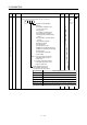
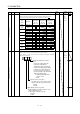
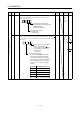
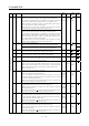
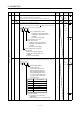
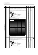
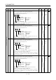
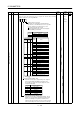
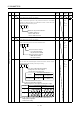
Table Of Contents
- Safety Instructions
- COMPLIANCE WITH EC DIRECTIVES
- CONFORMANCE WITH UL/C-UL STANDARD
- <
> - CONTENTS
- Optional Servo Motor Instruction Manual CONTENTS
- 1. FUNCTIONS AND CONFIGURATION
- 2. INSTALLATION
- 3. SIGNALS AND WIRING
- 3.1 Standard connection example
- 3.2 Internal connection diagram of servo amplifier
- 3.3 I/O signals
- 3.4 Detailed description of the signals
- 3.5 Alarm occurrence timing chart
- 3.6 Interfaces
- 3.7 Input power supply circuit
- 3.8 Connection of servo amplifier and servo motor
- 3.9 Servo motor with electromagnetic brake
- 3.10 Grounding
- 3.11 Servo amplifier terminal block (TE2) wiring method
- 3.12 Instructions for the 3M connector
- 3.13 Power line circuit of the MR-J2S-11KA to MR-J2S-22KA
- 4. OPERATION
- 5. PARAMETERS
- 6. DISPLAY AND OPERATION
- 7. GENERAL GAIN ADJUSTMENT
- 8. SPECIAL ADJUSTMENT FUNCTIONS
- 9. INSPECTION
- 10. TROUBLESHOOTING
- 11. OUTLINE DIMENSION DRAWINGS
- 12. CHARACTERISTICS
- 13. OPTIONS AND AUXILIARY EQUIPMENT
- 13.1 Options
- 13.1.1 Regenerative brake options
- 13.1.2 Brake unit
- 13.1.3 Power regeneration converter
- 13.1.4 External dynamic brake
- 13.1.5 Cables and connectors
- 13.1.6 Junction terminal block (MR-TB20)
- 13.1.7 Maintenance junction card (MR-J2CN3TM)
- 13.1.8 Battery (MR-BAT, A6BAT)
- 13.1.9 MR Configurator (Servo configurations software)
- 13.1.10 Power regeneration common converter
- 13.1.11 Heat sink outside mounting attachment (MR-JACN)
- 13.2 Auxiliary equipment
- 13.2.1 Recommended wires
- 13.2.2 No-fuse breakers, fuses, magnetic contactors
- 13.2.3 Power factor improving reactors
- 13.2.4 Power factor improving DC reactors
- 13.2.5 Relays
- 13.2.6 Surge absorbers
- 13.2.7 Noise reduction techniques
- 13.2.8 Leakage current breaker
- 13.2.9 EMC filter
- 13.2.10 Setting potentiometers for analog inputs
- 13.1 Options
- 14. COMMUNICATION FUNCTIONS
- 14.1 Configuration
- 14.2 Communication specifications
- 14.3 Protocol
- 14.4 Character codes
- 14.5 Error codes
- 14.6 Checksum
- 14.7 Time-out operation
- 14.8 Retry operation
- 14.9 Initialization
- 14.10 Communication procedure example
- 14.11 Command and data No. list
- 14.12 Detailed explanations of commands
- 14.12.1 Data processing
- 14.12.2 Status display
- 14.12.3 Parameter
- 14.12.4 External I/O pin statuses (DIO diagnosis)
- 14.12.5 Disable/enable of external I/O signals (DIO)
- 14.12.6 External input signal ON/OFF (test operation)
- 14.12.7 Test operation mode
- 14.12.8 Output signal pin ON/OFF output signal (DO) forced output
- 14.12.9 Alarm history
- 14.12.10 Current alarm
- 14.12.11 Other commands
- 15. ABSOLUTE POSITION DETECTION SYSTEM
- 15.1 Outline
- 15.2 Specifications
- 15.3 Battery installation procedure
- 15.4 Standard connection diagram
- 15.5 Signal explanation
- 15.6 Startup procedure
- 15.7 Absolute position data transfer protocol
- 15.8 Examples of use
- 15.9 Confirmation of absolute position detection data
- 15.10 Absolute position data transfer errors
- Appendix
- REVISIONS
5 - 21
5. PARAMETERS
Class No. Symbol Name and function
Initial
value
Unit
Setting
range
Control
mode
50 For manufacturer setting
Do not change this value by any means.
0000
51 *OP6 Function selection 6
Used to select the operation to be performed when the reset (RES)
switches on. This parameter is invalid (base circuit is shut off) in the
absolute position detection system.
0 00
Operation to be performed when the
reset (RES) switches on
0: Base circuit shut off
1: Base circuit not shut off
0000
Refer to
Name
and
function
column.
P S T
52 For manufacturer setting
Do not change this value by any means.
0000
53 *OP8 Function selection 8
Used to select the protocol of serial communication.
0 0
Protocol checksum selection
0: Yes (checksum added)
1: No (checksum not added)
Protocol checksum selection
0: With station numbers
1: No station numbers
0000
Refer to
Name
and
function
column.
P S T
Expansion parameters 2
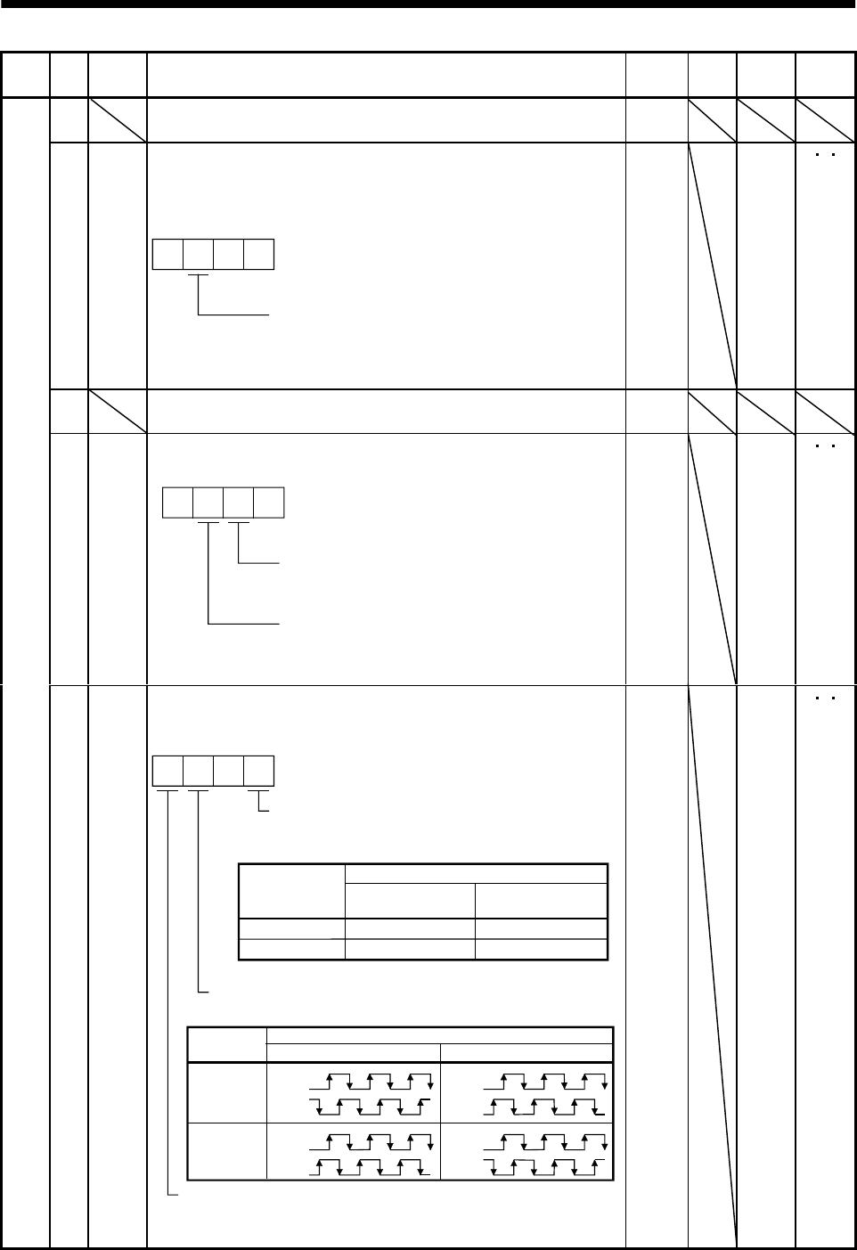
54 *OP9 Function selection 9
Use to select the command pulse rotation direction, encoder output
pulse direction and encoder pulse output setting.
0
0
1
CCW
CW
CW
CCW
Servo motor rotation direction changing
Changes the servo motor rotation
direction for the input pulse train.
Set value
Servo motor rotation direction
At forward rotation
pulse input (Note)
At reverse rotation
pulse input (Note)
Note. Refer to Section 3.4.1, (1), (a).
Encoder pulse output phase changing
Changes the phases of A, B-phase encoder pulses output .
Encoder output pulse setting selection (refer to parameter No. 27)
0: Output pulse designation
1: Division ratio setting
Servo motor rotation direction
Set value
CCW CW
0
1
A phase
B phase
A phase
B phase
A phase
B phase
A phase
B phase
0000
Refer to
Name
and
function
column.
P S T