
Car Amplifier User Manual
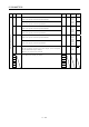
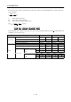
Table Of Contents
- Safety Instructions
- COMPLIANCE WITH EC DIRECTIVES
- CONFORMANCE WITH UL/C-UL STANDARD
- <
> - CONTENTS
- Optional Servo Motor Instruction Manual CONTENTS
- 1. FUNCTIONS AND CONFIGURATION
- 2. INSTALLATION
- 3. SIGNALS AND WIRING
- 3.1 Standard connection example
- 3.2 Internal connection diagram of servo amplifier
- 3.3 I/O signals
- 3.4 Detailed description of the signals
- 3.5 Alarm occurrence timing chart
- 3.6 Interfaces
- 3.7 Input power supply circuit
- 3.8 Connection of servo amplifier and servo motor
- 3.9 Servo motor with electromagnetic brake
- 3.10 Grounding
- 3.11 Servo amplifier terminal block (TE2) wiring method
- 3.12 Instructions for the 3M connector
- 3.13 Power line circuit of the MR-J2S-11KA to MR-J2S-22KA
- 4. OPERATION
- 5. PARAMETERS
- 6. DISPLAY AND OPERATION
- 7. GENERAL GAIN ADJUSTMENT
- 8. SPECIAL ADJUSTMENT FUNCTIONS
- 9. INSPECTION
- 10. TROUBLESHOOTING
- 11. OUTLINE DIMENSION DRAWINGS
- 12. CHARACTERISTICS
- 13. OPTIONS AND AUXILIARY EQUIPMENT
- 13.1 Options
- 13.1.1 Regenerative brake options
- 13.1.2 Brake unit
- 13.1.3 Power regeneration converter
- 13.1.4 External dynamic brake
- 13.1.5 Cables and connectors
- 13.1.6 Junction terminal block (MR-TB20)
- 13.1.7 Maintenance junction card (MR-J2CN3TM)
- 13.1.8 Battery (MR-BAT, A6BAT)
- 13.1.9 MR Configurator (Servo configurations software)
- 13.1.10 Power regeneration common converter
- 13.1.11 Heat sink outside mounting attachment (MR-JACN)
- 13.2 Auxiliary equipment
- 13.2.1 Recommended wires
- 13.2.2 No-fuse breakers, fuses, magnetic contactors
- 13.2.3 Power factor improving reactors
- 13.2.4 Power factor improving DC reactors
- 13.2.5 Relays
- 13.2.6 Surge absorbers
- 13.2.7 Noise reduction techniques
- 13.2.8 Leakage current breaker
- 13.2.9 EMC filter
- 13.2.10 Setting potentiometers for analog inputs
- 13.1 Options
- 14. COMMUNICATION FUNCTIONS
- 14.1 Configuration
- 14.2 Communication specifications
- 14.3 Protocol
- 14.4 Character codes
- 14.5 Error codes
- 14.6 Checksum
- 14.7 Time-out operation
- 14.8 Retry operation
- 14.9 Initialization
- 14.10 Communication procedure example
- 14.11 Command and data No. list
- 14.12 Detailed explanations of commands
- 14.12.1 Data processing
- 14.12.2 Status display
- 14.12.3 Parameter
- 14.12.4 External I/O pin statuses (DIO diagnosis)
- 14.12.5 Disable/enable of external I/O signals (DIO)
- 14.12.6 External input signal ON/OFF (test operation)
- 14.12.7 Test operation mode
- 14.12.8 Output signal pin ON/OFF output signal (DO) forced output
- 14.12.9 Alarm history
- 14.12.10 Current alarm
- 14.12.11 Other commands
- 15. ABSOLUTE POSITION DETECTION SYSTEM
- 15.1 Outline
- 15.2 Specifications
- 15.3 Battery installation procedure
- 15.4 Standard connection diagram
- 15.5 Signal explanation
- 15.6 Startup procedure
- 15.7 Absolute position data transfer protocol
- 15.8 Examples of use
- 15.9 Confirmation of absolute position detection data
- 15.10 Absolute position data transfer errors
- Appendix
- REVISIONS
5 - 24
5. PARAMETERS
Class No. Symbol Name and function
Initial
value
Unit
Setting
range
Control
mode
65 *CDP Gain changing selection
Used to select the gain changing condition. (Refer to Section 8.3.)
000
Gain changing selection
Gains are changed in accordance with the settings
of parameters No. 61 to 64 under any of the following
conditions:
0: Invalid
1: Gain changing (CDP) signal is ON
2: Command frequency is equal to higher than
parameter No. 66 setting
3: Droop pulse value is equal to higher than
parameter No. 66 setting
4: Servo motor speed is equal to higher than
parameter No. 66 setting
0000
Refer to
Name
and
function
column.
P S
66 CDS Gain changing condition
Used to set the value of gain changing condition (command
frequency, droop pulses, servo motor speed) selected in parameter
No. 65.The set value unit changes with the changing condition item.
(Refer to Section 8.5.)
10 kpps
pulse
r/min
10
to
9999
P
S
67 CDT Gain changing time constant
Used to set the time constant at which the gains will change in
response to the conditions set in parameters No. 65 and 66.
(Refer to Section 8.5.)
1ms0
to
100
P
S
68 For manufacturer setting
Do not change this value by any means.
0
69 CMX2 Command pulse multiplying factor numerator 2
Used to set the multiplier for the command pulse.
Setting "0" automatically sets the connected motor resolution.
10
1
to
65535
P
70 CMX3 Command pulse multiplying factor numerator 3
Used to set the multiplier for the command pulse.
Setting "0" automatically sets the connected motor resolution.
10
1
to
65535
P
71 CMX4 Command pulse multiplying factor numerator 4
Used to set the multiplier for the command pulse.
Setting "0" automatically sets the connected motor resolution.
10
1
to
65535
P
Internal speed command 4
Used to set speed 4 of internal speed commands.
S
Expansion parameters 2
72 SC4
Internal speed limit 4
Used to set speed 4 of internal speed limits.
200 r/min 0 to in-
stanta-
neous
permi-
ssible
speed
T