
Car Amplifier User Manual
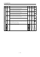
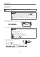
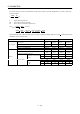
Table Of Contents
- Safety Instructions
- COMPLIANCE WITH EC DIRECTIVES
- CONFORMANCE WITH UL/C-UL STANDARD
- <
> - CONTENTS
- Optional Servo Motor Instruction Manual CONTENTS
- 1. FUNCTIONS AND CONFIGURATION
- 2. INSTALLATION
- 3. SIGNALS AND WIRING
- 3.1 Standard connection example
- 3.2 Internal connection diagram of servo amplifier
- 3.3 I/O signals
- 3.4 Detailed description of the signals
- 3.5 Alarm occurrence timing chart
- 3.6 Interfaces
- 3.7 Input power supply circuit
- 3.8 Connection of servo amplifier and servo motor
- 3.9 Servo motor with electromagnetic brake
- 3.10 Grounding
- 3.11 Servo amplifier terminal block (TE2) wiring method
- 3.12 Instructions for the 3M connector
- 3.13 Power line circuit of the MR-J2S-11KA to MR-J2S-22KA
- 4. OPERATION
- 5. PARAMETERS
- 6. DISPLAY AND OPERATION
- 7. GENERAL GAIN ADJUSTMENT
- 8. SPECIAL ADJUSTMENT FUNCTIONS
- 9. INSPECTION
- 10. TROUBLESHOOTING
- 11. OUTLINE DIMENSION DRAWINGS
- 12. CHARACTERISTICS
- 13. OPTIONS AND AUXILIARY EQUIPMENT
- 13.1 Options
- 13.1.1 Regenerative brake options
- 13.1.2 Brake unit
- 13.1.3 Power regeneration converter
- 13.1.4 External dynamic brake
- 13.1.5 Cables and connectors
- 13.1.6 Junction terminal block (MR-TB20)
- 13.1.7 Maintenance junction card (MR-J2CN3TM)
- 13.1.8 Battery (MR-BAT, A6BAT)
- 13.1.9 MR Configurator (Servo configurations software)
- 13.1.10 Power regeneration common converter
- 13.1.11 Heat sink outside mounting attachment (MR-JACN)
- 13.2 Auxiliary equipment
- 13.2.1 Recommended wires
- 13.2.2 No-fuse breakers, fuses, magnetic contactors
- 13.2.3 Power factor improving reactors
- 13.2.4 Power factor improving DC reactors
- 13.2.5 Relays
- 13.2.6 Surge absorbers
- 13.2.7 Noise reduction techniques
- 13.2.8 Leakage current breaker
- 13.2.9 EMC filter
- 13.2.10 Setting potentiometers for analog inputs
- 13.1 Options
- 14. COMMUNICATION FUNCTIONS
- 14.1 Configuration
- 14.2 Communication specifications
- 14.3 Protocol
- 14.4 Character codes
- 14.5 Error codes
- 14.6 Checksum
- 14.7 Time-out operation
- 14.8 Retry operation
- 14.9 Initialization
- 14.10 Communication procedure example
- 14.11 Command and data No. list
- 14.12 Detailed explanations of commands
- 14.12.1 Data processing
- 14.12.2 Status display
- 14.12.3 Parameter
- 14.12.4 External I/O pin statuses (DIO diagnosis)
- 14.12.5 Disable/enable of external I/O signals (DIO)
- 14.12.6 External input signal ON/OFF (test operation)
- 14.12.7 Test operation mode
- 14.12.8 Output signal pin ON/OFF output signal (DO) forced output
- 14.12.9 Alarm history
- 14.12.10 Current alarm
- 14.12.11 Other commands
- 15. ABSOLUTE POSITION DETECTION SYSTEM
- 15.1 Outline
- 15.2 Specifications
- 15.3 Battery installation procedure
- 15.4 Standard connection diagram
- 15.5 Signal explanation
- 15.6 Startup procedure
- 15.7 Absolute position data transfer protocol
- 15.8 Examples of use
- 15.9 Confirmation of absolute position detection data
- 15.10 Absolute position data transfer errors
- Appendix
- REVISIONS
5 - 31
5. PARAMETERS
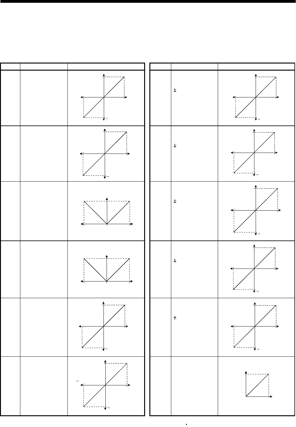
(2) Set content
The servo amplifier is factory-set to output the servo motor speed to analog monitor 1 (MO1) and the
torque to analog monitor (MO2). The setting can be changed as listed below by changing the
parameter No.17 value:
Refer to Appendix 2 for the measurement point.
Setting Output item Description Setting Output item Description
0Servo motor speed
8[V]
Max. speed
0
Max. speed
8[V]
CCW direction
CW direction
6 Droop pulses
(Note1)
(
10V/128pulse)
10[V]
0
128[pulse]
10[V]
CCW direction
CW direction
128[pulse]
1 Torque(Note2)
8[V]
Max. torque
0
Max. torque
8[V]
Drivin
g
in CW direction
Driving in CCW direction
7 Droop pulses
(Note1)
(
10V/2048pulse)
10[V]
0
2048[pulse]
10[V]
CCW direction
CW direction
2048[pulse]
2Servo motor speed
8[V]
Max. speed
0
Max. speed
CCW
direction
CW
direction
8 Droop pulses
(Note1)
(
10V/8192pulse)
10[V]
0
8192[pulse]
10[V]
CCW direction
CW direction
8192[pulse]
3 Torque(Note2)
8[V]
Max. torque
0
Max. torque
Driving in
CW direction
Driving in
CCW direction
9 Droop pulses
(Note1)
(
10V/32768pulse)
10[V]
0
32768[pulse]
10[V]
CCW direction
CW direction
32768[pulse]
4 Current command
8[V]
Max. command
current
(Max. torque
command)
0
Max. command
current
(Max. torque
command)
8[V]
CCW direction
CW direction
A Droop pulses
(Note1)
(
10V/131072pulse)
10[V]
0
131072[pulse]
10[V]
CCW direction
CW direction
131072[pulse]
5Command pulse
frequency
10[V]
500kpps
0
500kpps
10[V]
CCW direction
CW direction
BBus voltage
8[V]
0
400[V]
Note1. Encoder pulse unit.
2. 8V is outputted at the maximum torque.However, when parameter No.28
76 are set to limit torgue, 8V is outputted
at the torque highly limited.