
Car Amplifier User Manual
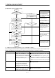
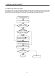

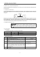
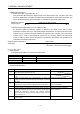
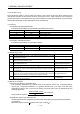
Table Of Contents
- Safety Instructions
- COMPLIANCE WITH EC DIRECTIVES
- CONFORMANCE WITH UL/C-UL STANDARD
- <
> - CONTENTS
- Optional Servo Motor Instruction Manual CONTENTS
- 1. FUNCTIONS AND CONFIGURATION
- 2. INSTALLATION
- 3. SIGNALS AND WIRING
- 3.1 Standard connection example
- 3.2 Internal connection diagram of servo amplifier
- 3.3 I/O signals
- 3.4 Detailed description of the signals
- 3.5 Alarm occurrence timing chart
- 3.6 Interfaces
- 3.7 Input power supply circuit
- 3.8 Connection of servo amplifier and servo motor
- 3.9 Servo motor with electromagnetic brake
- 3.10 Grounding
- 3.11 Servo amplifier terminal block (TE2) wiring method
- 3.12 Instructions for the 3M connector
- 3.13 Power line circuit of the MR-J2S-11KA to MR-J2S-22KA
- 4. OPERATION
- 5. PARAMETERS
- 6. DISPLAY AND OPERATION
- 7. GENERAL GAIN ADJUSTMENT
- 8. SPECIAL ADJUSTMENT FUNCTIONS
- 9. INSPECTION
- 10. TROUBLESHOOTING
- 11. OUTLINE DIMENSION DRAWINGS
- 12. CHARACTERISTICS
- 13. OPTIONS AND AUXILIARY EQUIPMENT
- 13.1 Options
- 13.1.1 Regenerative brake options
- 13.1.2 Brake unit
- 13.1.3 Power regeneration converter
- 13.1.4 External dynamic brake
- 13.1.5 Cables and connectors
- 13.1.6 Junction terminal block (MR-TB20)
- 13.1.7 Maintenance junction card (MR-J2CN3TM)
- 13.1.8 Battery (MR-BAT, A6BAT)
- 13.1.9 MR Configurator (Servo configurations software)
- 13.1.10 Power regeneration common converter
- 13.1.11 Heat sink outside mounting attachment (MR-JACN)
- 13.2 Auxiliary equipment
- 13.2.1 Recommended wires
- 13.2.2 No-fuse breakers, fuses, magnetic contactors
- 13.2.3 Power factor improving reactors
- 13.2.4 Power factor improving DC reactors
- 13.2.5 Relays
- 13.2.6 Surge absorbers
- 13.2.7 Noise reduction techniques
- 13.2.8 Leakage current breaker
- 13.2.9 EMC filter
- 13.2.10 Setting potentiometers for analog inputs
- 13.1 Options
- 14. COMMUNICATION FUNCTIONS
- 14.1 Configuration
- 14.2 Communication specifications
- 14.3 Protocol
- 14.4 Character codes
- 14.5 Error codes
- 14.6 Checksum
- 14.7 Time-out operation
- 14.8 Retry operation
- 14.9 Initialization
- 14.10 Communication procedure example
- 14.11 Command and data No. list
- 14.12 Detailed explanations of commands
- 14.12.1 Data processing
- 14.12.2 Status display
- 14.12.3 Parameter
- 14.12.4 External I/O pin statuses (DIO diagnosis)
- 14.12.5 Disable/enable of external I/O signals (DIO)
- 14.12.6 External input signal ON/OFF (test operation)
- 14.12.7 Test operation mode
- 14.12.8 Output signal pin ON/OFF output signal (DO) forced output
- 14.12.9 Alarm history
- 14.12.10 Current alarm
- 14.12.11 Other commands
- 15. ABSOLUTE POSITION DETECTION SYSTEM
- 15.1 Outline
- 15.2 Specifications
- 15.3 Battery installation procedure
- 15.4 Standard connection diagram
- 15.5 Signal explanation
- 15.6 Startup procedure
- 15.7 Absolute position data transfer protocol
- 15.8 Examples of use
- 15.9 Confirmation of absolute position detection data
- 15.10 Absolute position data transfer errors
- Appendix
- REVISIONS
7 - 3
7. GENERAL GAIN ADJUSTMENT
7.2 Auto tuning
7.2.1 Auto tuning mode
The servo amplifier has a real-time auto tuning function which estimates the machine characteristic (load
inertia moment ratio) in real time and automatically sets the optimum gains according to that value. This
function permits ease of gain adjustment of the servo amplifier.
(1) Auto tuning mode 1
The servo amplifier is factory-set to the auto tuning mode 1.
In this mode, the load inertia moment ratio of a machine is always estimated to set the optimum gains
automatically.
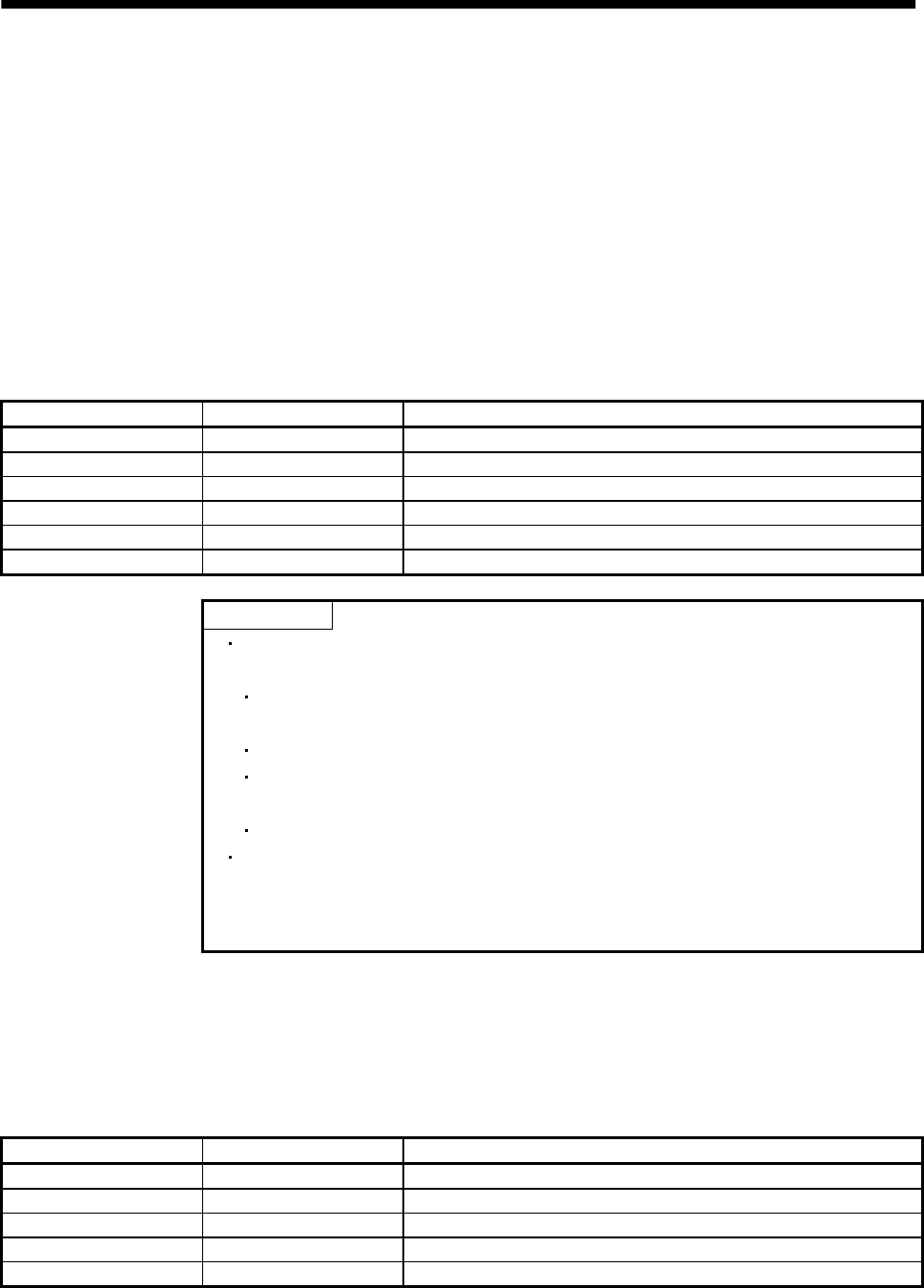
The following parameters are automatically adjusted in the auto tuning mode 1.
Parameter No. Abbreviation Name
6PG1Position control gain 1
34 GD2 Ratio of load inertia moment to servo motor inertia moment
35 PG2 Position control gain 2
36 VG1 Speed control gain 1
37 VG2 Speed control gain 2
38 VIC Speed integral compensation
POINT
The auto tuning mode 1 may not be performed properly if the following
conditions are not satisfied.
Time to reach 2000r/min is the acceleration/deceleration time constant of 5s or
less.
Speed is 150r/min or higher.
The ratio of load inertia moment to servo motor inertia moment is 100
times or less.
The acceleration/deceleration torque is 10% or more of the rated torque.
Under operating conditions which will impose sudden disturbance torque
during acceleration/deceleration or on a machine which is extremely loose,
auto tuning may not function properly, either. In such cases, use the auto
tuning mode 2 or manual mode 1,2 to make gain adjustment.
(2) Auto tuning mode 2
Use the auto tuning mode 2 when proper gain adjustment cannot be made by auto tuning mode 1.
Since the load inertia moment ratio is not estimated in this mode, set the value of a correct load
inertia moment ratio (parameter No. 34).
The following parameters are automatically adjusted in the auto tuning mode 2.
Parameter No. Abbreviation Name
6PG1Position control gain 1
35 PG2 Position control gain 2
36 VG1 Speed control gain 1
37 VG2 Speed control gain 2
38 VIC Speed integral compensation