
Car Amplifier User Manual
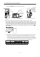
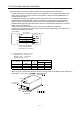
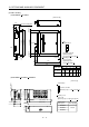
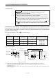
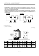
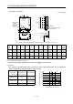
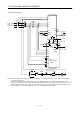
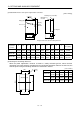
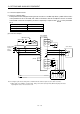
Table Of Contents
- Safety Instructions
- COMPLIANCE WITH EC DIRECTIVES
- CONFORMANCE WITH UL/C-UL STANDARD
- <
> - CONTENTS
- Optional Servo Motor Instruction Manual CONTENTS
- 1. FUNCTIONS AND CONFIGURATION
- 2. INSTALLATION
- 3. SIGNALS AND WIRING
- 3.1 Standard connection example
- 3.2 Internal connection diagram of servo amplifier
- 3.3 I/O signals
- 3.4 Detailed description of the signals
- 3.5 Alarm occurrence timing chart
- 3.6 Interfaces
- 3.7 Input power supply circuit
- 3.8 Connection of servo amplifier and servo motor
- 3.9 Servo motor with electromagnetic brake
- 3.10 Grounding
- 3.11 Servo amplifier terminal block (TE2) wiring method
- 3.12 Instructions for the 3M connector
- 3.13 Power line circuit of the MR-J2S-11KA to MR-J2S-22KA
- 4. OPERATION
- 5. PARAMETERS
- 6. DISPLAY AND OPERATION
- 7. GENERAL GAIN ADJUSTMENT
- 8. SPECIAL ADJUSTMENT FUNCTIONS
- 9. INSPECTION
- 10. TROUBLESHOOTING
- 11. OUTLINE DIMENSION DRAWINGS
- 12. CHARACTERISTICS
- 13. OPTIONS AND AUXILIARY EQUIPMENT
- 13.1 Options
- 13.1.1 Regenerative brake options
- 13.1.2 Brake unit
- 13.1.3 Power regeneration converter
- 13.1.4 External dynamic brake
- 13.1.5 Cables and connectors
- 13.1.6 Junction terminal block (MR-TB20)
- 13.1.7 Maintenance junction card (MR-J2CN3TM)
- 13.1.8 Battery (MR-BAT, A6BAT)
- 13.1.9 MR Configurator (Servo configurations software)
- 13.1.10 Power regeneration common converter
- 13.1.11 Heat sink outside mounting attachment (MR-JACN)
- 13.2 Auxiliary equipment
- 13.2.1 Recommended wires
- 13.2.2 No-fuse breakers, fuses, magnetic contactors
- 13.2.3 Power factor improving reactors
- 13.2.4 Power factor improving DC reactors
- 13.2.5 Relays
- 13.2.6 Surge absorbers
- 13.2.7 Noise reduction techniques
- 13.2.8 Leakage current breaker
- 13.2.9 EMC filter
- 13.2.10 Setting potentiometers for analog inputs
- 13.1 Options
- 14. COMMUNICATION FUNCTIONS
- 14.1 Configuration
- 14.2 Communication specifications
- 14.3 Protocol
- 14.4 Character codes
- 14.5 Error codes
- 14.6 Checksum
- 14.7 Time-out operation
- 14.8 Retry operation
- 14.9 Initialization
- 14.10 Communication procedure example
- 14.11 Command and data No. list
- 14.12 Detailed explanations of commands
- 14.12.1 Data processing
- 14.12.2 Status display
- 14.12.3 Parameter
- 14.12.4 External I/O pin statuses (DIO diagnosis)
- 14.12.5 Disable/enable of external I/O signals (DIO)
- 14.12.6 External input signal ON/OFF (test operation)
- 14.12.7 Test operation mode
- 14.12.8 Output signal pin ON/OFF output signal (DO) forced output
- 14.12.9 Alarm history
- 14.12.10 Current alarm
- 14.12.11 Other commands
- 15. ABSOLUTE POSITION DETECTION SYSTEM
- 15.1 Outline
- 15.2 Specifications
- 15.3 Battery installation procedure
- 15.4 Standard connection diagram
- 15.5 Signal explanation
- 15.6 Startup procedure
- 15.7 Absolute position data transfer protocol
- 15.8 Examples of use
- 15.9 Confirmation of absolute position detection data
- 15.10 Absolute position data transfer errors
- Appendix
- REVISIONS
13 - 6
13. OPTIONS AND AUXILIARY EQUIPMENT
For the MR-RB50 MR-RB51 install the cooling fan as shown.
82.5 40 (1.58)
82.5
133
Fan installation screw hole dimensions
2-M3 screw hole
(for fan installation)
Depth 10 or less
(Screw hole already
machined)
Recommended fan:
Toyo Denki's TL396A or equivalent
Fan Terminal block
Thermal relay
Installation surface
Horizontal installation
Vertical
installation
Top
Bottom
(3.25)
(5.24)
(3.25)
[Unit : mm(in)]
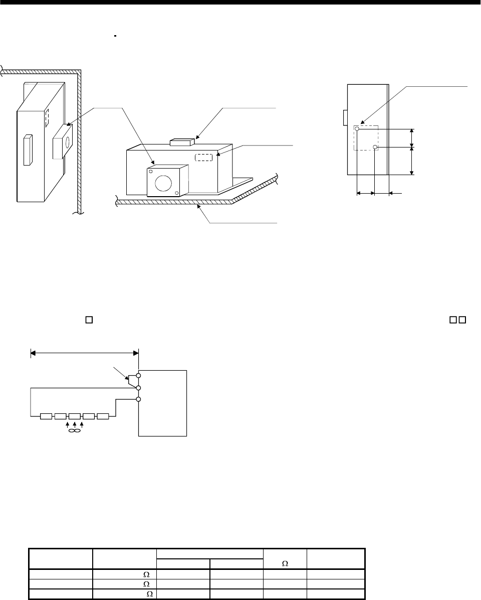
(c) MR-J2S-11KA to MR-J2S-22KA (when using the supplied regenerative brake resistor)
When using the regenerative brake resistors supplied to the servo amplifier, the specified number
of resistors (4 or 5 resistors) must be connected in series. If they are connected in parallel or in less
than the specified number, the servo amplifier may become faulty and/or the regenerative brake
resistors burn. Install the resistors at intervals of about 70mm. Cooling the resistors with fans
(1.0m
3
/min, 92 (about two fans) improves the regeneration capability. In this case, set "0E " in
parameter No. 0.
P
C
Servo amplifier
(Note) Series connection
Fan
P
1
Do not remove
the short bar.
5m or less
Note. The number of resistors connected in series depends on the resistor type. Install a thermal sensor or like to configure a
circuit that will shut off the main circuit power at abnormal overheat. The supplied regenerative brake resistor does not
have a built-in thermal sensor. If the regenerative brake circuit fails, abnormal overheat of the resistor is expected to
occur. On the customer side, please also install a thermal sensor for the resistor and provide a protective circuit that will
shut off the main circuit power supply at abnormal overheat. The detection level of the thermal sensor changes depending
on the resistor installation method. Please install the thermal sensor in the optimum position according to the customer's
design standards, or use our regenerative brake option having built-in thermal sensor (MR-RB65, 66, 67).
Regenerative Power [W]
Servo Amplifier
Regenerative
Brake Resistor
Normal Cooling
Resistance
[
]
Number of
Resistors
MR-J2S-11KA GRZG400-2 500 800 8 4
MR-J2S-15KA GRZG400-1 850 1300 5 5
MR-J2S-22KA GRZG400-0.8 850 1300 4 5