
Car Amplifier User Manual
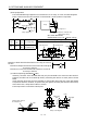
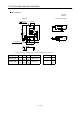
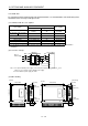
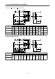
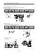
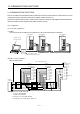
Table Of Contents
- Safety Instructions
- COMPLIANCE WITH EC DIRECTIVES
- CONFORMANCE WITH UL/C-UL STANDARD
- <
> - CONTENTS
- Optional Servo Motor Instruction Manual CONTENTS
- 1. FUNCTIONS AND CONFIGURATION
- 2. INSTALLATION
- 3. SIGNALS AND WIRING
- 3.1 Standard connection example
- 3.2 Internal connection diagram of servo amplifier
- 3.3 I/O signals
- 3.4 Detailed description of the signals
- 3.5 Alarm occurrence timing chart
- 3.6 Interfaces
- 3.7 Input power supply circuit
- 3.8 Connection of servo amplifier and servo motor
- 3.9 Servo motor with electromagnetic brake
- 3.10 Grounding
- 3.11 Servo amplifier terminal block (TE2) wiring method
- 3.12 Instructions for the 3M connector
- 3.13 Power line circuit of the MR-J2S-11KA to MR-J2S-22KA
- 4. OPERATION
- 5. PARAMETERS
- 6. DISPLAY AND OPERATION
- 7. GENERAL GAIN ADJUSTMENT
- 8. SPECIAL ADJUSTMENT FUNCTIONS
- 9. INSPECTION
- 10. TROUBLESHOOTING
- 11. OUTLINE DIMENSION DRAWINGS
- 12. CHARACTERISTICS
- 13. OPTIONS AND AUXILIARY EQUIPMENT
- 13.1 Options
- 13.1.1 Regenerative brake options
- 13.1.2 Brake unit
- 13.1.3 Power regeneration converter
- 13.1.4 External dynamic brake
- 13.1.5 Cables and connectors
- 13.1.6 Junction terminal block (MR-TB20)
- 13.1.7 Maintenance junction card (MR-J2CN3TM)
- 13.1.8 Battery (MR-BAT, A6BAT)
- 13.1.9 MR Configurator (Servo configurations software)
- 13.1.10 Power regeneration common converter
- 13.1.11 Heat sink outside mounting attachment (MR-JACN)
- 13.2 Auxiliary equipment
- 13.2.1 Recommended wires
- 13.2.2 No-fuse breakers, fuses, magnetic contactors
- 13.2.3 Power factor improving reactors
- 13.2.4 Power factor improving DC reactors
- 13.2.5 Relays
- 13.2.6 Surge absorbers
- 13.2.7 Noise reduction techniques
- 13.2.8 Leakage current breaker
- 13.2.9 EMC filter
- 13.2.10 Setting potentiometers for analog inputs
- 13.1 Options
- 14. COMMUNICATION FUNCTIONS
- 14.1 Configuration
- 14.2 Communication specifications
- 14.3 Protocol
- 14.4 Character codes
- 14.5 Error codes
- 14.6 Checksum
- 14.7 Time-out operation
- 14.8 Retry operation
- 14.9 Initialization
- 14.10 Communication procedure example
- 14.11 Command and data No. list
- 14.12 Detailed explanations of commands
- 14.12.1 Data processing
- 14.12.2 Status display
- 14.12.3 Parameter
- 14.12.4 External I/O pin statuses (DIO diagnosis)
- 14.12.5 Disable/enable of external I/O signals (DIO)
- 14.12.6 External input signal ON/OFF (test operation)
- 14.12.7 Test operation mode
- 14.12.8 Output signal pin ON/OFF output signal (DO) forced output
- 14.12.9 Alarm history
- 14.12.10 Current alarm
- 14.12.11 Other commands
- 15. ABSOLUTE POSITION DETECTION SYSTEM
- 15.1 Outline
- 15.2 Specifications
- 15.3 Battery installation procedure
- 15.4 Standard connection diagram
- 15.5 Signal explanation
- 15.6 Startup procedure
- 15.7 Absolute position data transfer protocol
- 15.8 Examples of use
- 15.9 Confirmation of absolute position detection data
- 15.10 Absolute position data transfer errors
- Appendix
- REVISIONS

13 - 52
13. OPTIONS AND AUXILIARY EQUIPMENT
13.2.9 EMC filter
For compliance with the EMC directive of the EN Standard, it is recommended to use the following filter:
Some EMC filters are large in leakage current.
(1) Combination with the servo amplifier
Recommended filter
Servo amplifier
Model Leakage current [mA]
Mass [kg]([lb])
MR-J2S-10A to MR-J2S-100A
MR-J2S-10A1 to MR-J2S-40A1
SF1252 38 0.75(1.65)
MR-J2S-200A MR-J2S-350A SF1253 57 1.37(3.02)
MR-J2S-500A (Note) HF3040A-TM 1.5 5.5(12.13)
MR-J2S-700A (Note) HF3050A-TM 1.5 6.7(14.77)
MR-J2S-11KA (Note) HF3060A-TMA 3.0 10.0(22.05)
MR-J2S-15KA (Note) HF3080A-TMA 3.0 13.0(28.66)
MR-J2S-22KA (Note) HF3100A-TMA 3.0 14.5(31.97)
Note: Soshin Electric A surge protector is separately required to use any of these EMC filters. (Refer to the EMC Installation
Guidelines.)
(2) Connection example
NFB
L
1
L
2
L
3
L
11
L
21
L
1
L
2
L
3
LINE LOAD
EMC filter Servo amplifier
(Note 1)
Power supply
(Note 2)
Note 1. For 1-phase 230VAC power supply, connect the power supply to L
1
,L
2
and leave L
3
open.
There is no L
3
for 1-phase 100 to 120VAC power supply.
2. Connect when the power supply has earth.
L
1
L
2
L
3
MC
(3) Outline drawing
23.0(0.906)
LABEL
LINELOAD
168.0(6.614)
L1'
L2'
L3'
L1
L2
L3
149.5(5.886)
LINE
(input side)
LOAD
(output side)
140.0(5.512)
156.0(6.142)
16.0(0.63)
42.0
8.5
SF1252
LABEL
LINELOAD
168.0(6.614)
L1'
L2'
L3'
L1
L2
L3
209.5(8.248)
LINE
(input side)
LOAD
(output side)
140.0(5.512)
156.0(6.142)
49.0
8.5
SF1253
[Unit: mm(in)]
(0.335)
(1.654)
(0.335)
(1.929)
6.0(0.236)
6.0(0.236)