
Car Amplifier User Manual

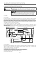
Table Of Contents
- Safety Instructions
- COMPLIANCE WITH EC DIRECTIVES
- CONFORMANCE WITH UL/C-UL STANDARD
- <
> - CONTENTS
- Optional Servo Motor Instruction Manual CONTENTS
- 1. FUNCTIONS AND CONFIGURATION
- 2. INSTALLATION
- 3. SIGNALS AND WIRING
- 3.1 Standard connection example
- 3.2 Internal connection diagram of servo amplifier
- 3.3 I/O signals
- 3.4 Detailed description of the signals
- 3.5 Alarm occurrence timing chart
- 3.6 Interfaces
- 3.7 Input power supply circuit
- 3.8 Connection of servo amplifier and servo motor
- 3.9 Servo motor with electromagnetic brake
- 3.10 Grounding
- 3.11 Servo amplifier terminal block (TE2) wiring method
- 3.12 Instructions for the 3M connector
- 3.13 Power line circuit of the MR-J2S-11KA to MR-J2S-22KA
- 4. OPERATION
- 5. PARAMETERS
- 6. DISPLAY AND OPERATION
- 7. GENERAL GAIN ADJUSTMENT
- 8. SPECIAL ADJUSTMENT FUNCTIONS
- 9. INSPECTION
- 10. TROUBLESHOOTING
- 11. OUTLINE DIMENSION DRAWINGS
- 12. CHARACTERISTICS
- 13. OPTIONS AND AUXILIARY EQUIPMENT
- 13.1 Options
- 13.1.1 Regenerative brake options
- 13.1.2 Brake unit
- 13.1.3 Power regeneration converter
- 13.1.4 External dynamic brake
- 13.1.5 Cables and connectors
- 13.1.6 Junction terminal block (MR-TB20)
- 13.1.7 Maintenance junction card (MR-J2CN3TM)
- 13.1.8 Battery (MR-BAT, A6BAT)
- 13.1.9 MR Configurator (Servo configurations software)
- 13.1.10 Power regeneration common converter
- 13.1.11 Heat sink outside mounting attachment (MR-JACN)
- 13.2 Auxiliary equipment
- 13.2.1 Recommended wires
- 13.2.2 No-fuse breakers, fuses, magnetic contactors
- 13.2.3 Power factor improving reactors
- 13.2.4 Power factor improving DC reactors
- 13.2.5 Relays
- 13.2.6 Surge absorbers
- 13.2.7 Noise reduction techniques
- 13.2.8 Leakage current breaker
- 13.2.9 EMC filter
- 13.2.10 Setting potentiometers for analog inputs
- 13.1 Options
- 14. COMMUNICATION FUNCTIONS
- 14.1 Configuration
- 14.2 Communication specifications
- 14.3 Protocol
- 14.4 Character codes
- 14.5 Error codes
- 14.6 Checksum
- 14.7 Time-out operation
- 14.8 Retry operation
- 14.9 Initialization
- 14.10 Communication procedure example
- 14.11 Command and data No. list
- 14.12 Detailed explanations of commands
- 14.12.1 Data processing
- 14.12.2 Status display
- 14.12.3 Parameter
- 14.12.4 External I/O pin statuses (DIO diagnosis)
- 14.12.5 Disable/enable of external I/O signals (DIO)
- 14.12.6 External input signal ON/OFF (test operation)
- 14.12.7 Test operation mode
- 14.12.8 Output signal pin ON/OFF output signal (DO) forced output
- 14.12.9 Alarm history
- 14.12.10 Current alarm
- 14.12.11 Other commands
- 15. ABSOLUTE POSITION DETECTION SYSTEM
- 15.1 Outline
- 15.2 Specifications
- 15.3 Battery installation procedure
- 15.4 Standard connection diagram
- 15.5 Signal explanation
- 15.6 Startup procedure
- 15.7 Absolute position data transfer protocol
- 15.8 Examples of use
- 15.9 Confirmation of absolute position detection data
- 15.10 Absolute position data transfer errors
- Appendix
- REVISIONS
15 - 1
15. ABSOLUTE POSITION DETECTION SYSTEM
15. ABSOLUTE POSITION DETECTION SYSTEM
CAUTION
If an absolute position erase alarm (AL.25) or an absoluto position counter marning
(AL.E3) has occurred, always perform home position setting again. Not doing so
can cause runaway.
POINT
When configuring an absolute position detection system using the QD75P/D
PLC, refer to the Type QD75P/QD75D Positioning Module User's Manual
QD75P1/QD75P2/QD75P4, QD75D1/QD75D2/QD75D4 (SH (NA) 080058).
15.1 Outline
15.1.1 Features
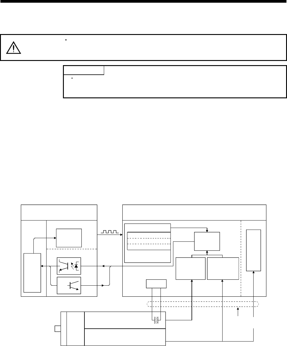
For normal operation, as shown below, the encoder consists of a detector designed to detect a position
within one revolution and a cumulative revolution counter designed to detect the number of revolutions.
The absolute position detection system always detects the absolute position of the machine and keeps it
battery-backed, independently of whether the general-purpose programming controller power is on or off.
Therefore, once the home position is defined at the time of machine installation, home position return is
not needed when power is switched on thereafter.
If a power failure or a fault occurs, restoration is easy.
Also, the absolute position data, which is battery-backed by the super capacitor in the encoder, can be
retained within the specified period (cumulative revolution counter value retaining time) if the cable is
unplugged or broken.
LSO
1XO
MR-BAT
CPU
General purpose programmable
controller
Servo amplifier
Pulse train
(command)
Changing the
current position
data
Positioning module
I/O module
Current
position
data
Input
Output
Home position data
EEPROM memory
Backed up in the
case of power failure
Current
position
data
Detecting the
number of
revolutions
LS 1X
Detecting the
position within
one revolution
Position control
Speed control
Servo motor
1 pulse/rev Accumulative
revolution counter
Super capacitor
Within-one-revolution counter
(
Position detector
)
High speed serial
communication
Battery
15.1.2 Restrictions
The absolute position detection system cannot be configured under the following conditions. Test
operation cannot be performed in the absolute position detection system, either. To perform test
operation, choose incremental in parameter No.1.
(1) Speed control mode, torque control mode.
(2) Control switch-over mode (position/speed, speed/torque, torque/position).
(3) Stroke-less coordinate system, e.g. rotary shaft, infinitely long positioning.
(4) Changing of electronic gear after home position setting.
(5) Use of alarm code output.