
Car Amplifier User Manual
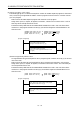
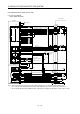
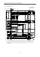
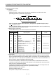
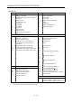
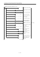
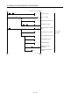
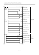
Table Of Contents
- Safety Instructions
- COMPLIANCE WITH EC DIRECTIVES
- CONFORMANCE WITH UL/C-UL STANDARD
- <
> - CONTENTS
- Optional Servo Motor Instruction Manual CONTENTS
- 1. FUNCTIONS AND CONFIGURATION
- 2. INSTALLATION
- 3. SIGNALS AND WIRING
- 3.1 Standard connection example
- 3.2 Internal connection diagram of servo amplifier
- 3.3 I/O signals
- 3.4 Detailed description of the signals
- 3.5 Alarm occurrence timing chart
- 3.6 Interfaces
- 3.7 Input power supply circuit
- 3.8 Connection of servo amplifier and servo motor
- 3.9 Servo motor with electromagnetic brake
- 3.10 Grounding
- 3.11 Servo amplifier terminal block (TE2) wiring method
- 3.12 Instructions for the 3M connector
- 3.13 Power line circuit of the MR-J2S-11KA to MR-J2S-22KA
- 4. OPERATION
- 5. PARAMETERS
- 6. DISPLAY AND OPERATION
- 7. GENERAL GAIN ADJUSTMENT
- 8. SPECIAL ADJUSTMENT FUNCTIONS
- 9. INSPECTION
- 10. TROUBLESHOOTING
- 11. OUTLINE DIMENSION DRAWINGS
- 12. CHARACTERISTICS
- 13. OPTIONS AND AUXILIARY EQUIPMENT
- 13.1 Options
- 13.1.1 Regenerative brake options
- 13.1.2 Brake unit
- 13.1.3 Power regeneration converter
- 13.1.4 External dynamic brake
- 13.1.5 Cables and connectors
- 13.1.6 Junction terminal block (MR-TB20)
- 13.1.7 Maintenance junction card (MR-J2CN3TM)
- 13.1.8 Battery (MR-BAT, A6BAT)
- 13.1.9 MR Configurator (Servo configurations software)
- 13.1.10 Power regeneration common converter
- 13.1.11 Heat sink outside mounting attachment (MR-JACN)
- 13.2 Auxiliary equipment
- 13.2.1 Recommended wires
- 13.2.2 No-fuse breakers, fuses, magnetic contactors
- 13.2.3 Power factor improving reactors
- 13.2.4 Power factor improving DC reactors
- 13.2.5 Relays
- 13.2.6 Surge absorbers
- 13.2.7 Noise reduction techniques
- 13.2.8 Leakage current breaker
- 13.2.9 EMC filter
- 13.2.10 Setting potentiometers for analog inputs
- 13.1 Options
- 14. COMMUNICATION FUNCTIONS
- 14.1 Configuration
- 14.2 Communication specifications
- 14.3 Protocol
- 14.4 Character codes
- 14.5 Error codes
- 14.6 Checksum
- 14.7 Time-out operation
- 14.8 Retry operation
- 14.9 Initialization
- 14.10 Communication procedure example
- 14.11 Command and data No. list
- 14.12 Detailed explanations of commands
- 14.12.1 Data processing
- 14.12.2 Status display
- 14.12.3 Parameter
- 14.12.4 External I/O pin statuses (DIO diagnosis)
- 14.12.5 Disable/enable of external I/O signals (DIO)
- 14.12.6 External input signal ON/OFF (test operation)
- 14.12.7 Test operation mode
- 14.12.8 Output signal pin ON/OFF output signal (DO) forced output
- 14.12.9 Alarm history
- 14.12.10 Current alarm
- 14.12.11 Other commands
- 15. ABSOLUTE POSITION DETECTION SYSTEM
- 15.1 Outline
- 15.2 Specifications
- 15.3 Battery installation procedure
- 15.4 Standard connection diagram
- 15.5 Signal explanation
- 15.6 Startup procedure
- 15.7 Absolute position data transfer protocol
- 15.8 Examples of use
- 15.9 Confirmation of absolute position detection data
- 15.10 Absolute position data transfer errors
- Appendix
- REVISIONS
15 - 34
15. ABSOLUTE POSITION DETECTION SYSTEM
(4) Sequence program - 2-axis control
The following program is a reference example for creation of an ABS sequence program for the second
axis (Y axis) using a single A1SD71 module. Create a program for the third axis in a similar manner.
(a) Y-axis program
Refer to the X-axis ABS sequence program and create the Y-axis program.
Assign the X inputs, Y outputs, D registers, M contacts, T timers and C counters of the Y axis so
that they do not overlap those of the X axis.
The buffer memory addresses of the A1SD71 differ between the X and Y axes. The instructions
marked *1 in the program of Section 15.8.1 (3), (c) should be changed as indicated below for use
with the Y axis:
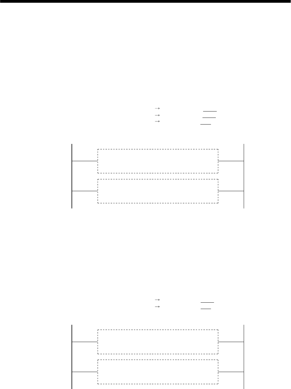
[Program configuration]
X-axis ABS sequence program
(Program in Section 15.8.1 (3), (f))
Y-axis ABS sequence program
(Refer to the X-axis program and write the Y-axis
program)
[FROMP H0001 K7872 D8 K1]
[DFROP H0001 K7912 D9 K1]
[DTOP H0001 K41 D3 K1]
[FROMP H0001 K7892 D8 K1]
[DFROP H0001 K7922 D9 K1]
[DTOP H0001 K341 D3 K1]
(b) Data set type home position return
Arrange the data set type home position return programs given in Section 15.8.1 (3), (f) in series to
control two axes.
Refer to the X-axis data set type home position return program and create the Y-axis program.
Assign the X inputs, Y outputs, D registers, M contacts and T timers of the Y axis so that they do
not overlap those of the X axis.
The buffer memory addresses of the A1SD75 differ between the X and Y axes. The instructions
marked *1 in the program of Section 15.8.1 (3), (f) should be changed as indicated below for use
with the Y axis:
[Program configuration]
X-axis data set type home position return program
(Program in Section 15.8.1 (3), (f))
Y-axis data set type home position return program
(Refer to the X-axis program and write the Y-axis
program)
[DTOP H0001 K7912 D9 K1]
[DTOP H0001 K41 D9 K1]
[DTOP H0001 K7922 D9 K1]
[DTOP H0001 K341 D9 K1]