
Car Amplifier User Manual
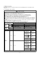
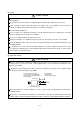
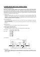
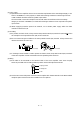
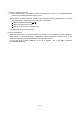
Table Of Contents
- Safety Instructions
- COMPLIANCE WITH EC DIRECTIVES
- CONFORMANCE WITH UL/C-UL STANDARD
- <
> - CONTENTS
- Optional Servo Motor Instruction Manual CONTENTS
- 1. FUNCTIONS AND CONFIGURATION
- 2. INSTALLATION
- 3. SIGNALS AND WIRING
- 3.1 Standard connection example
- 3.2 Internal connection diagram of servo amplifier
- 3.3 I/O signals
- 3.4 Detailed description of the signals
- 3.5 Alarm occurrence timing chart
- 3.6 Interfaces
- 3.7 Input power supply circuit
- 3.8 Connection of servo amplifier and servo motor
- 3.9 Servo motor with electromagnetic brake
- 3.10 Grounding
- 3.11 Servo amplifier terminal block (TE2) wiring method
- 3.12 Instructions for the 3M connector
- 3.13 Power line circuit of the MR-J2S-11KA to MR-J2S-22KA
- 4. OPERATION
- 5. PARAMETERS
- 6. DISPLAY AND OPERATION
- 7. GENERAL GAIN ADJUSTMENT
- 8. SPECIAL ADJUSTMENT FUNCTIONS
- 9. INSPECTION
- 10. TROUBLESHOOTING
- 11. OUTLINE DIMENSION DRAWINGS
- 12. CHARACTERISTICS
- 13. OPTIONS AND AUXILIARY EQUIPMENT
- 13.1 Options
- 13.1.1 Regenerative brake options
- 13.1.2 Brake unit
- 13.1.3 Power regeneration converter
- 13.1.4 External dynamic brake
- 13.1.5 Cables and connectors
- 13.1.6 Junction terminal block (MR-TB20)
- 13.1.7 Maintenance junction card (MR-J2CN3TM)
- 13.1.8 Battery (MR-BAT, A6BAT)
- 13.1.9 MR Configurator (Servo configurations software)
- 13.1.10 Power regeneration common converter
- 13.1.11 Heat sink outside mounting attachment (MR-JACN)
- 13.2 Auxiliary equipment
- 13.2.1 Recommended wires
- 13.2.2 No-fuse breakers, fuses, magnetic contactors
- 13.2.3 Power factor improving reactors
- 13.2.4 Power factor improving DC reactors
- 13.2.5 Relays
- 13.2.6 Surge absorbers
- 13.2.7 Noise reduction techniques
- 13.2.8 Leakage current breaker
- 13.2.9 EMC filter
- 13.2.10 Setting potentiometers for analog inputs
- 13.1 Options
- 14. COMMUNICATION FUNCTIONS
- 14.1 Configuration
- 14.2 Communication specifications
- 14.3 Protocol
- 14.4 Character codes
- 14.5 Error codes
- 14.6 Checksum
- 14.7 Time-out operation
- 14.8 Retry operation
- 14.9 Initialization
- 14.10 Communication procedure example
- 14.11 Command and data No. list
- 14.12 Detailed explanations of commands
- 14.12.1 Data processing
- 14.12.2 Status display
- 14.12.3 Parameter
- 14.12.4 External I/O pin statuses (DIO diagnosis)
- 14.12.5 Disable/enable of external I/O signals (DIO)
- 14.12.6 External input signal ON/OFF (test operation)
- 14.12.7 Test operation mode
- 14.12.8 Output signal pin ON/OFF output signal (DO) forced output
- 14.12.9 Alarm history
- 14.12.10 Current alarm
- 14.12.11 Other commands
- 15. ABSOLUTE POSITION DETECTION SYSTEM
- 15.1 Outline
- 15.2 Specifications
- 15.3 Battery installation procedure
- 15.4 Standard connection diagram
- 15.5 Signal explanation
- 15.6 Startup procedure
- 15.7 Absolute position data transfer protocol
- 15.8 Examples of use
- 15.9 Confirmation of absolute position detection data
- 15.10 Absolute position data transfer errors
- Appendix
- REVISIONS
A - 8
(4) Power supply
(a) Operate the servo amplifier 7kW or less to meet the requirements of the overvoltage category II set
forth in IEC60664-1. For this purpose, a reinforced insulating transformer conforming to the IEC
or EN standard should be used in the power input section.
Since the 11kW or more servo amplifier can be used under the conditions of the overvoltage
category III set forth in IE60664-1, a reinforced insulating transformer is not required in the power
input section.
(b) When supplying interface power from external, use a 24VDC power supply which has been
insulation-reinforced in I/O.
(5) Grounding
(a) To prevent an electric shock, always connect the protective earth (PE) terminals (marked
) of the
servo amplifier to the protective earth (PE) of the control box.
(b) Do not connect two ground cables to the same protective earth (PE) terminal. Always connect the
cables to the terminals one-to-one.
PE terminals
PE terminals
(c) If a leakage current breaker is used to prevent an electric shock, the protective earth (PE) terminals
of the servo amplifier must be connected to the corresponding earth terminals.
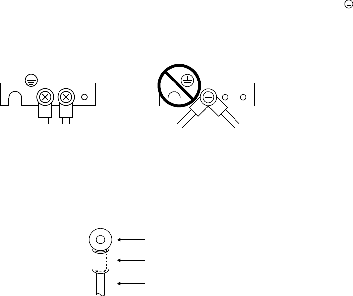
(6) Wiring
(a) The cables to be connected to the terminal block of the servo amplifier must have crimping
terminals provided with insulating tubes to prevent contact with adjacent terminals.
Crimping terminal
Insulating tube
Cable
(b) Use the servo motor side power connector which complies with the EN Standard. The EN Standard
compliant power connector sets are available from us as options.