OB427B-1.qxp 07.5.16 3:30 PM Page 1 Revision B: •Remote controller model has been changed. •RoHS PARTS LIST has been added. SPLIT-TYPE, HEAT PUMP AIR CONDITIONERS Please void OB427 REVISED EDITION-A. INDOOR UNIT No. OB427 SERVICE MANUAL REVISED EDITION-B Wireless type Models MSH-A18ND MSH-A24ND - S1 S1 Outdoor unit service manual MUH-A·ND Series (OB428) CONTENTS MSH-A18ND MSH-A24ND 1. TECHNICAL CHANGES ····································2 2.
OB427B-1.qxp 07.5.17 7:35 AM Page 2 Revision A: • Parts No. of 10.PARTS LIST has been revised. Revision B: •Remote controller model has been changed. (KP0A ➔ KM04A) Both remote controllers can be used as alternative. •RoHS PARTS LIST has been added. 1 TECHNICAL CHANGES MSH-18TN - S1 ➔ MSH-A18ND - S1 MSH-24TN - S1 ➔ MSH-A24ND - S1 1. 2. 3. 4. Model name has been changed. Grille design has been changed. Unit size has been changed.
OB427B-1.qxp 07.5.16 3:30 PM Page 3 REMOTE CONTROLLER MSH-A18ND MSH-A24ND Signal transmitting section Operation display section PM OPERATE /STOP (ON /OFF) button AM TOO ON/OFF WARM TOO COOL TEMPERATURE buttons Indication of remote controller model is on back. Open the front lid. CLOCK PM AM TOO ON/OFF WARM VANE button (Horizontal vane button) TOO COOL FAN STOP VANE START I FEEL COOL FAN SPEED CONTROL button OFF-TIMER button HEAT DRY ON-TIMER button MODE WIDE VANE HR.
OB427B-1.qxp 3 07.5.16 3:30 PM Page 4 SPECIFICATION Indoor model MSH-A18ND Function Power supply Special remarks Fan motor Electrical data Capacity Air flow (High/Med./Low) Running current Power input Power factor Model Current Winding resistance (at 20:) Dimensions WOHOD Weight Air direction Sound level (High/Med./Low) Fan speed (High/Med./Low) Fan speed regulator Remote controller model Heating Single phase 220V, 60Hz 768/642/516 0.28 60 97 RC4N32-AA 0.28 WHT-BLK 205.5 BLK-RED 217.
07.5.16 3:30 PM 4 Page 5 OUTLINES AND DIMENSIONS MSH-A18ND MSH-A24ND Unit: mm Installation plate Indoor unit 98 7.5 173 98 414.5 414.5 173 2.5 47 255.5 1068 315 INDOOR UNIT 47 OB427B-1.qxp Wall hole [75 258 1100 Air in 5 Installation plate { 325 { 791 56 253 Air out Drain hose [16 (Connected part O.D) Insulation [28 19 162 58 Liquid line [ 6.35- 0.5m Gas line [ 12-0.43m Insulation [ 50 O.D [ 32 I.D for MSH-A18ND Liquid line [ 9.52- 0.5m Gas line [ 12-0.
OB427B-1.qxp 07.5.16 3:30 PM 5 Page 6 WIRING DIAGRAM MSH-A18ND INDOOR UNIT TO OUTDOOR UNIT CONNECTING TB 12V 3 HIC1 N 220V~ CN201 3 2 1 RED BLU 2 NR11 GRN/YLW CN 151 CN 102 15 MV2 MV2 MV1 RT12 CN 111 RT11 3 CN 121 1 3 F11 SR141 4 CN211 ELECTRONIC CONTROL P.C. BOARD C11 TAB12 BRN CN 112 CN 101 3 3 DISPLAY P.C.BOARD RECEIVER P.C.BOARD BLK GRY YLW BRN WHT RED MF REMOTE CONTROLLER SYMBOL NAME SYMBOL NAME C11 INDOOR FAN CAPACITOR MV1 VANE MOTOR (HORIZONTAL) F11 FUSE (3.
OB427B-1.qxp 07.5.16 3:30 PM 6 Page 7 REFRIGERANT SYSTEM DIAGRAM MSH-A18ND MSH-A24ND INDOOR UNIT INDOOR UNIT Unit:mm Refrigerant pipe [15.88 (with heat insulator) Refrigerant pipe [12.
OB427B-1.qxp 7 07.5.16 3:30 PM Page 8 SERVICE FUNCTIONS MSH-A18ND MSH-A24ND 7-1. TIMER SHORT MODE For service, set time can be shortened by short circuit of JPG and JPS on the electronic control P.C. board. The time will be shortened as follows. Set time : 1 minute ➔ 1-second Set time : 3 minute ➔ 3-second (It takes 3 minutes for the compressor to start operation. However, the starting time is shortened by short circuit of JPG and JPS.) 7-2. P.C.
OB427B-1.qxp 07.5.16 3:30 PM Page 9 How to release “AUTO RESTART FUNCTION” 1Turn off the main power for the unit. 2Pull out the electronic control P.C. board, the receiver P.C. C11 board and the display P.C.board. (Refer to 9-2.) 3Solder jumper wire to JR07 on the indoor electronic control P.C. board. (Refer to 8-6.) CN 21 1 CN201 SW1 RA102 CN151 CN121 CN111 CN112 TAB12 IC101 IC152 JR07 Operation 1If the main power has been cut, the operation settings remain.
OB427B-1.qxp 8 07.5.16 3:30 PM Page 10 TROUBLESHOOTING MSH-A18ND MSH-A24ND 8-1. Cautions on troubleshooting 1. Before troubleshooting, check the following: (1) Check the power supply voltage. (2) Check the indoor/outdoor connecting wire for mis-wiring. 2.
OB427B-1.qxp 07.5.16 3:30 PM Page 11 8-2. Instruction of troubleshooting Start Indoor unit operates. Outdoor unit doesn't operate normally. Indoor unit operates. Outdoor unit doesn't operate. Outdoor unit operates when the EMERGENCY OPERATION switch is pressed. Outdoor unit doesn't operate when the EMERGENCY OPERATION switch is pressed. Outdoor unit doesn't stop even if indoor unit stops. Check room temperature thermistor. Refer to 8-6. "Test point diagram and voltage".
OB427B-1.qxp 07.5.16 3:30 PM Page 12 8-3. Troubleshooting check table • The following indication applies regardless of shape of the indicator. • Before taking measures, make sure that the symptom reappears for accurate troubleshooting. When the indoor unit has started operation and the following detection method has detected an abnormality (the first detection after the power ON), the indoor electronic control P.C. board turns OFF the indoor fan motor with the OPERATION INDICATOR lamp flashing.
OB427B-1.qxp 07.5.16 3:30 PM Page 13 8-4. Trouble criterion of main parts MSH-A18ND MSH-A24ND Part name Check method and criterion Measure the resistance with a tester.
OB427B-1.qxp 07.5.16 3:30 PM Page 14 8-5. Troubleshooting flow When OPERATION INDICATOR lamp flashes 3-time. Indoor fan motor doesn’t operate. A Check of indoor fan motor Turn OFF the power supply. Check connector CN211 visually. No Are lead wires connected? Yes Is soldered point of the connector correctly soldered? No Resolder it. Yes Reconnect the lead wires. Disconnect lead wires from connector CN211 on the indoor electronic control P.C. board. Measure resistance between lead wires No.
OB427B-1.qxp 07.5.16 3:30 PM Page 15 The unit doesn’t operate with the remote controller. Also, the OPERATION INDICATOR lamp doesn’t light up by pressing the EMERGENCY OPERATION switch. C Check of indoor electronic control P.C. board Check the both “parts side” and “pattern side” of indoor electronic control P.C. board visually. Varistor (NR11) Turn OFF the power supply. Remove indoor fan motor connector CN211 and vane motor connector CN151 from the indoor electronic control P.C.
OB427B-1.qxp 07.5.16 3:30 PM Page 16 When OPERATION INDICATOR lamp flashes ON and OFF in every 0.5-second. Outdoor unit doesn’t operate. D How to check mis-wiring w Short circuit of JPG and JPS on the indoor electronic control P.C. board enables self -check to be displayed in 3 seconds. Start • Turn ON the power supply. (outdoor unit) • Press EMERGENCY OPERATION switch once. After 3 minutes, mis-wiring is indicated (0.5-second ON, 0.5-second OFF) on OPERATION INDICATOR lamp on indoor unit.
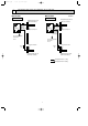
OB427B-1.qxp 07.5.16 3:30 PM Page 17 8-6. Test point diagram and voltage MSH-A18ND MSH-A24ND Indoor electronic control P.C. board Fan motor power supply } Power supply input 220V AC + Fuse (F11) 250V AC 3.15A } 5V DC Room temperature thermistor(RT11) Indoor coil thermistor(RT12(main)) PS132 MSH-A24ND Indoor coil thermistor(RT13(sub)) Emergency operation switch Timer short mode point (JPS, JPG) (Refer to 7-1.) + } Receiver P.C.
OB427B-1.qxp 9 07.5.16 3:30 PM Page 18 DISASSEMBLY INSTRUCTIONS <"Terminal with locking mechanism" Detaching points> The terminal which has the locking mechanism can be detached as shown below. There are two types ( Refer to (1) and (2)) of the terminal with locking mechanism. The terminal without locking mechanism can be detached by pulling it out. Check the shape of the terminal before detaching. (1) Slide the sleeve and check if there is a locking lever or not.
OB427B-1.qxp 07.5.16 3:30 PM Page 19 OPERATING PROCEDURE PHOTOS 3. Removing the electrical box (1) Remove the front panel. (Refer to 1.) (2) Remove the electrical cover. (Refer to 2.) (3) Disconnect the connector of the indoor coil thermistor. (4) Disconnect the motor connector (CN211 and CN121) and the vane motor connector (CN151) on the electronic control P.C. board. (5) Remove the screws of ground wire. (6) Remove the fan motor lead wire and indoor coil thermistor from the electrical box.
OB427B-1.qxp 10 07.5.16 3:30 PM Page 20 PARTS LIST (non-RoHS compliant) MSH-A18ND MSH-A24ND 10-1. INDOOR UNIT STRUCTURAL PARTS 10-2. INDOOR UNIT HEAT EXCHANGER 1 2 11 3 9 4 8 (See 10-5.) 5 12 13 6 7 10-1. INDOOR UNIT STRUCTURAL PARTS Part number that is circled is not shown in the illustration. NO. 1 2 3 4 5 6 7 8 9 10 Part No.
OB427B-1.qxp 07.5.16 3:30 PM Page 21 PARTS LIST (non-RoHS compliant) MSH-A18ND MSH-A24ND 10-4. ACCESSORY AND REMOTE CONTROLLER 10-3. INDOOR UNIT FUNCTIONAL PARTS AND ELECTRICAL PARTS 1 20 19 23 24 2 3 4 11 18 12 5 6 14 13 10 7 8 9 17 15 16 10-3. INDOOR UNIT FUNCTIONAL PARTS AND ELECTRICAL PARTS Part numbers that are circled are not shown in the illustration. NO. 1 2 3 4 5 6 7 8 9 10 11 12 13 14 15 16 17 18 19 20 21 22 Part No.
OB427B-1.qxp 07.5.16 3:30 PM Page 22 PARTS LIST (non-RoHS compliant) 10-5. AIR CLEANING FILTER ● AIR CLEANING FILTER removes fine dust of 0.01 micron from air by means of static electricity. ● Normal life of AIR CLEANING FILTER is 4 months. However, when it becomes dirty, replace it as soon as possible. ● Clogged AIR CLEANING FILTER may reduce the air conditioner capacity or cause frost on the air outlet. ● DO NOT reuse AIR CLEANING FILTER even if it is washed.
OB427B-1.qxp 07.5.16 3:30 PM 11 Page 23 RoHS PARTS LIST (RoHS compliant) MSH-A18ND MSH-A24ND 11-1. INDOOR UNIT STRUCTURAL PARTS 11-2. INDOOR UNIT HEAT EXCHANGER 1 2 11 3 9 4 5 8 (See 11-5.) 12 13 6 7 11-1. INDOOR UNIT STRUCTURAL PARTS NO. RoHS Part number that is circled is not shown in the illustration. 1 2 3 4 5 6 7 8 9 10 G G G G G G G G G G Part Name Part No.
OB427B-1.qxp 07.5.16 3:30 PM Page 24 RoHS PARTS LIST (RoHS compliant) MSH-A18ND MSH-A24ND 11-4. ACCESSORY AND REMOTE CONTROLLER 11-3. INDOOR UNIT FUNCTIONAL PARTS AND ELECTRICAL PARTS 1 20 19 23 24 2 3 4 11 18 12 5 6 14 13 10 7 8 9 17 15 16 11-3. INDOOR UNIT FUNCTIONAL PARTS AND ELECTRICAL PARTS NO. 1 2 3 4 5 6 7 8 9 10 11 12 13 14 15 16 17 18 19 20 21 22 RoHS Part numbers that are circled are not shown in the illustration. G G G G G G G G G G G G G G G G G G G G G G G G G G Part No.
OB427B-1.qxp 07.5.16 3:30 PM Page 25 RoHS PARTS LIST (RoHS compliant) 11-5. AIR CLEANING FILTER ● AIR CLEANING FILTER removes fine dust of 0.01 micron from air by means of static electricity. ● Normal life of AIR CLEANING FILTER is 4 months. However, when it becomes dirty, replace it as soon as possible. ● Clogged AIR CLEANING FILTER may reduce the air conditioner capacity or cause frost on the air outlet. ● DO NOT reuse AIR CLEANING FILTER even if it is washed.
OB427B-1.qxp 07.5.
OB427B-1.qxp 07.5.
OB427B-1.qxp 07.5.17 7:37 AM Page 28 TM HEAD OFFICE: TOKYO BLDG., 2-7-3, MARUNOUCHI, CHIYODA-KU, TOKYO 100-8310, JAPAN C Copyright 2005 MITSUBISHI ELECTRIC ENGINEERING CO.,LTD Distributed in May 2007. No.OB427 REVISED EDITION-B 6 Distributed in Feb. 2006. No.OB427 REVISED EDITION-A 106 Distributed in Nov. 2005. No.OB427 106 Made in Japan New publication, effective May 2007 Specifications subject to change without notice.