Revision A: • 3. SPECIFICATION has been corrected. Please void OBH497. INDOOR UNIT No. OBH497 SERVICE MANUAL REVISED EDITION-A Wireless type Models MSZ-FD09NA MSZ-FD12NA Outdoor unit service manual MUZ-FD•NA Series (OBH498) MXZ-A·NA Series (OB444) CONTENTS 1. TECHNICAL CHANGES······································· 3 2. PART NAMES AND FUNCTIONS ····················· 4 3. SPECIFICATION ················································ 5 4. OUTLINES AND DIMENSIONS ························ 7 5.
Revision A: • 3. SPECIFICATION has been corrected.
1 TECHNICAL CHANGES MSZ-FD09NA MSZ-FD12NA 1. New model.
2 PART NAMES AND FUNCTIONS MSZ-FD09NA MSZ-FD12NA AREA lamp POWER lamp Remote control receiving section Operation indicator lamp Front panel Air filter Air inlet Remote controller Platinum deodorizing filter Anti-allergy Enzyme Filter i-see Sensor Air outlet Horizontal vane Emergency operation switch Fan Heat exchanger AREA lamp indicates AREA setting In AREA setting, the horizontal air flow direction changes automatically according to the detection of i-see Sensor which detects the floor/ wall
3 SPECIFICATION Indoor model Power supply V, phase, Hz Max. fuse size (time delay)/ Disconnect switch A Min. circuit ampacity A Fan motor F.L.A HEAT Dry CFM Airflow COOL Dry Low - Med. - High CFM (Wet) Moisture removal pt./h Cooling dB(A) Sound level Low - Med. - High Heating dB(A) Cond. drain connection O.D. in. W in. Dimensions D in. H in. Weight Ib. External finish Remote controller Control voltage (by built-in transformer) MSZ-FD09NA MSZ-FD12NA 208/230 , 1 , 60 15 1.0 1.0 0.
3-1. OPERATING RANGE (1) POWER SUPPLY Rated voltage 208/230 V 1 phase 60 Hz Indoor unit Guaranteed Voltage Min.187 V 208 V 230 V Max.253 V (2) OPERATION Intake air temperature (°F) Mode Condition Indoor DB 80 90 67 Standard temperature Maximum temperature Cooling Minimum temperature Maximum humidity Standard temperature Heating Maximum temperature Minimum temperature Outdoor WB 67 73 57 DB 95 115 14 60 67 60 47 75 14 78 % 70 80 70 WB — — — — 43 65 13 3-2.
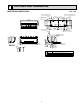
OUTLINES AND DIMENSIONS MSZ-FD09NA MSZ-FD12NA Unit : inch 7/16 X 1 Oblong hole 8-7/8 2-1/2 1-5/8 1-7/8 Indoor unit 6-1/8 2-1/8 6-1/8 13-9/16 13 3-15/16 1/2 2-3/16 3/4 Air out Installation plate Piping 1-11/16 3-3/8 3-13/16 Drain hose 6-1/4 2-5/16 1/4 2-3/16 2-11/16 11-5/8 27-1/16 2-3/16 1-11/16 2-11/16 Wall hole ø2-9/16 Air in 10-1/8 9-1/8 1/8 8-3/8 8-5/16 1/2 10 31-3/8 30-7/8 7/8 8-7/8 Installation plate 9-15/16 2-1/2 7/16 X 13/16 Oblong hole 1-5/8 4 Piping Insulat
5 WIRING DIAGRAM MSZ-FD09NA MSZ-FD12NA 8
6 REFRIGERANT SYSTEM DIAGRAM MSZ-FD09NA MSZ-FD12NA Unit:inch Refrigerant pipe 3/8 (with heat insulator) Indoor heat exchanger Indoor coil thermistor RT12 (main) Flared connection Indoor coil thermistor RT13 (sub) Room temperature thermistor RT11 Flared connection Refrigerant pipe 1/4 (with heat insulator) Refrigerant flow in cooling Refrigerant flow in heating 9
7 SERVICE FUNCTIONS MSZ-FD09NA MSZ-FD12NA 7-1. TIMER SHORT MODE For service, set time can be shortened by short circuit of JPG and JPS the indoor electronic control P.C. board. The time will be shortened as follows. (Refer to 9-7.) Set time : 1-minute 1-second Set time : 3-minute 3-second (It takes 3 minutes for the compressor to start operation. However, the starting time is shortened by short circuit of JPG and JPS.) 7-2. P.C.
7-3. AUTO RESTART FUNCTION When the indoor unit is controlled with the remote controller, the operation mode, the set temperature, and the fan speed are memorized by the indoor electronic control P.C. board. “AUTO RESTART FUNCTION” automatically starts operation in the same mode just before the shutoff of the main power. Operation If the main power has been cut, the operation settings remain. After the power is restored, the unit restarts automatically according to the memory.
8 MICROPROCESSOR CONTROL MSZ-FD09NA MSZ-FD12NA WIRELESS REMOTE CONTROLLER Signal transmitting section Operation display section OPERATE/STOP (ON/OFF) button FAN SPEED CONTROL button OPERATION SELECT button POWERFUL button VANE CONTROL button OFF TIMER button ON TIMER button TIME SET buttons FORWARD button BACKWARD button Temperature buttons i-see button AREA button RESET button WIDE VANE button (Vertical vane button) CLOCK SET button Indication of remote controller model is on back NOTE: Last setti
8-1. COOL ( ) OPERATION (1) Press OPERATE/STOP (ON/OFF) button. POWER lamp of the indoor unit turns on with a beep tone. (2) Select COOL mode with OPERATION SELECT button. (3) Press TEMPERATURE buttons (TOO WARM or TOO COOL button) to select the desired temperature. The setting range is 61 ~ 88°F (16 ~ 31°C). 1. Coil frost prevention The compressor operational frequency is controlled by the temperature of the indoor heat exchanger to prevent the coil from frosting.
8-4. AUTO CHANGE OVER ··· AUTO MODE OPERATION Once desired temperature is set, unit operation is switched automatically between COOL and HEAT operation. Mode selection (1) Initial mode When unit starts the operation with AUTO operation from off; • If the room temperature is higher than the set temperature, operation starts in COOL mode. • If the room temperature is equal to or lower than the set temperature, operation starts in HEAT mode.
(3) Positioning To confirm the standard position, the vane moves until it touches the vane stopper. Then the vane is set to the selected angle. Confirming of standard position is performed in the following cases: (a) The operation starts or finishes (including timer operation). (b) The test run operation starts. (c) Standby mode (only during multi system operation) starts or finishes.
(10) POWERFUL ( ) operation. The air conditioner automatically adjusts the fan speed and the set temperature, and operates the POWERFUL mode. The POWERFUL mode is automatically released 15 minutes after operation starts, and the operation mode returns to the mode prior to POWERFUL operation 2. Vertical vane (1) Vane motor drive These models are equipped with a stepping motor for the vertical vane. The rotating direction, speed, and angle of the motor are controlled by pulse signals (approx.
8-6. i-see CONTROL OPERATION The sensors constantly measure the room and floor/wall temperatures to automatically adjust to the set temperature by estimating the temperature actually perceived by a person inside the room (“sensory temperature”). Advantages · The air inside the room is conditioned quickly to a comfortable condition. · The room will not become too cold or hot even when the air conditioner is kept on for a long period.
Indoor unit installation location and air-conditioning area Installed at left LEFT Installed at center RIGHT LEFT Installed at right RIGHT LEFT RIGHT ·Be sure to set the slide switch inside the remote controller to an appropriate position in accordance with the installed position of the indoor unit. If the switch is not set correctly, the air conditioner may not function properly. (Refer to "Remote controller in SERVICE FUNCTIONS".
Operation and operating range i-see sensor moves 30 degrees from the center in both right and left side. i-see Sensor turning to the left i-see Sensor turning to the center i-see Sensor turning to the right i-see Sensor operates as follows in accordance with AREA setting made with the remote controller. “AUTO” in AREA setting; first turning to the LEFT for adjusting the position then ····· CENTER RIGHT CENTER LEFT CENTER ····· (The sensor turns to the right, left and center.
8-8. TIMER OPERATION 1. How to set the time (1) Check that the current time is set correctly. NOTE : Timer operation will not work without setting the current time. Initially “0:00 AM” blinks at the current time display of TIME MONITOR, so set the current time correctly with CLOCK SET button. How to set the current time (a) Press the CLOCK set button. (b) Press the TIME SET buttons ( ) to set the current time.
8-9. EMERGENCY/TEST OPERATION In case of test run operation or emergency operation, use EMERGENCY OPERATION switch on the right side of the indoor unit. Emergency operation is available when the remote controller is missing, has failed or the batteries of the remote controller run down. The unit will start and AREA lamp will light. The first 30 minutes of operation is the test run operation. This operation is for servicing.
9 TROUBLESHOOTING MSZ-FD09NA MSZ-FD12NA 9-1. CAUTIONS ON TROUBLESHOOTING 1. Before troubleshooting, check the following 1) Check the power supply voltage. 2) Check the indoor/outdoor connecting wire for miswiring. 2. Take care of the following during servicing 1) Before servicing the air conditioner, be sure to turn off the unit first with the remote controller, and then after confirming the horizontal vane is closed, turn off the breaker and/or disconnect the power plug.
9-2. FAILURE MODE RECALL FUNCTION Outline of the function This air conditioner can memorize the abnormal condition which has occurred once. Even though LED indication listed on the troubleshooting check table (9-4.) disappears, the memorized failure details can be recalled. This mode is very useful when the unit needs to be repaired for the abnormality which doesn't recur. 1.
2. Indoor unit failure mode table POWER Not lighted Abnormal point (Failure mode) Normal Condition Correspondence — The room temperature thermistor short or open 1-time flash every Room temperature circuit is detected every 8 seconds during op0.5-second thermistor eration. 2-time flash Indoor coil thermis- The indoor coil thermistor short or open circuit 2.5-second OFF tor is detected every 8 seconds during operation. 3-time flash The serial signal from outdoor unit is not reSerial signal 2.
9-3. INSTRUCTION OF TROUBLESHOOTING Start Indoor unit operates. Outdoor unit doesn't operate. Indoor unit operates. Outdoor unit doesn't operate normally. Indoor unit doesn't receive the signal from remote controller. OPERATION INDICATOR lamp on the indoor unit is flashing on and off. If blinking of OPERATION INDICATOR lamp cannot be checked, it can be checked with failure mode recall function. Outdoor unit operates only in Test Run operation. Outdoor unit doesn't operate even in Test Run operation.
9-4. TROUBLESHOOTING CHECK TABLE Before taking measures, make sure that the symptom reappears for accurate troubleshooting. When the indoor unit has started operation and the following detection method has detected an abnormality (the first detection after the power ON), the indoor electronic control P.C. board turns OFF the indoor fan motor with OPERATION INDICATOR lamp flashing. L AREA R POWER Lighted Blinking Not lighted No.
L AREA R No. Abnormal point POWER Operation indicator lamp POWER lamp is lighted. AREA lamps flash. 1 MXZ type Operation mode setting 2.5-second OFF Symptom Condition Correspondence The operation mode of the each indoor unit Outdoor unit is differently set to COOL (includes DRY) and • Unify the operation mode. operates but HEAT at the same time, the operation mode Refer to outdoor unit service indoor unit does of the indoor unit that has operated at first has manual. not operate. the priority.
9-5. TROUBLE CRITERION OF MAIN PARTS MSZ-FD09NA MSZ-FD12NA Part name Check method and criterion Room temperature therm- Measure the resistance with a tester. istor (RT11) Refer to 9-7. "Test point diagram and voltage", "Indoor electronic control P.C. board", the chart of thermistor. Indoor coil thermistor (RT12, RT13) Indoor fan motor (MF) Figure Check 9-6. . Measure the resistance between the terminals with a tester.
9-6. TROUBLESHOOTING FLOW A Check of indoor fan motor The indoor fan motor error has occurred, and the indoor fan doesn't operate. Turn OFF the power supply. Pay careful attention to the high voltage on the fan motor connector CN211. Is there any foreign matter that interferes the rotation of the line flow fan? Turn ON the power supply, wait 5 seconds or more, and then press EMERGENCY OPERATION switch. Measure the supply voltage as follows within 12 seconds after EMERGENCY OPERATION switch is pressed.
B Check of remote controller and indoor electronic control P.C. board Check if the remote controller is exclusive for this air conditioner. Press OPERATE/STOP (ON/OFF) button on the remote controller. Is LCD display on the remote controller visible? Yes No (Not clear) Replace the batteries. (Refer to 9-1.4.) Remove the batteries, then set them back and press RESET button. (Refer to 9-1.4.) Check if the unit operates with the remote controller.
C Check of indoor electronic control P.C. board and indoor fan motor Turn OFF the power supply. Remove indoor fan motor connector CN211, vane motor connector CN151 and the i-see Sensor motor connector CN110 from the indoor electronic control P.C. board and turn ON the power supply. Does the unit operate with the remote controller? Does POWER lamp light up by pressing EMERGENCY OPERATION switch? No Yes Measure the resistance of the i-see Sensor motor coil. (Refer to 9-5.
D How to check miswiring and serial signal error Turn OFF the power supply. Is there rated voltage in the power supply? Check the power supply. No Yes Turn ON the power supply. Is there rated voltage between outdoor terminal block S1 and S2? Yes Check the wiring. No Press EMERGENCY OPERATION switch once.
E Electromagnetic noise enters into TV sets or radios Is the unit grounded? Yes Is the distance between the antennas and the indoor unit within 9.91 ft., or is the distance between the antennas and the outdoor unit within 9.91 ft.? Ground the unit. No Yes Extend the distance between the antennas and the indoor unit, and/or the antennas and the outdoor unit. Yes Extend the distance between the TV sets and/or radios and the indoor unit, or the TV sets or radios and the outdoor unit.
9-7. TEST POINT DIAGRAM AND VOLTAGE MSZ-FD09NA MSZ-FD12NA Indoor electronic control P.C. board 5 VDC Cement resistor (R111) 12 VDC Indoor fan motor (CN211) 294/325 VDC Power supply input 208/230 VAC (-) Fiducial terminal of cathode side on measuring high-voltage DC 15 VDC (+)3 - 6 VDC (+)0 or 15 VDC { Room temperature thermistor RT11 (CN111) Varistor (NR11) CN201 (Used for check of conducting of thermal fuse) SW P.C.
2. Power monitor receiver P.C. board 3. Monitor P.C.
10 DISASSEMBLY INSTRUCTIONS <"Terminal with locking mechanism" Detaching points> The terminal which has the locking mechanism can be detached as shown below. There are two types (refer to (1) and (2)) of the terminal with locking mechanism. The terminal without locking mechanism can be detached by pulling it out. Check the shape of the terminal before detaching. (1) Slide the sleeve and check if there is a locking lever or not. Sleeve Locking lever Slide the sleeve.
OPERATING PROCEDURE PHOTOS 2. Removing the electronic control P.C. board, the power monitor receiver P.C. board, i-see Sensor, SW P.C. board and the terminal block (1) Remove the panel (refer to 1.) and the corner box. (2) Remove the screw of the conduit cover. Remove the conduit cover and then the indoor/outdoor connecting wire. (See Photo 2) (3) Remove the sensor holder from the electrical cover. (See Photo 3) (4) Remove the screw of the electrical cover, and then the electrical cover.
OPERATING PROCEDURE PHOTOS Photo 5 3. Removing the electrical box (1) Remove the panel (Refer to 1.) and the corner box. (2) Remove the indoor/outdoor connecting wire, the sensor holder, the electrical cover and the ground wire. (Refer to 2.) (3) Disconnect the following connectors on the electronic control P.C. board; CN211 (Fan motor) CN112 (Indoor coil thermistor) CN1U1 (Horizontal vane motor) CN151 (Vertical vane motor) (4) Unhook the catches of the electrical box, and pull out the electrical box.
OPERATING PROCEDURE PHOTOS 6. Removing the horizontal vane motor (1) Remove the nozzle assembly. (Refer to 4.) (2) Remove the screws of the horizontal vane motor unit, and pull out the horizontal vane motor unit. (3) Remove the screws of the horizontal vane motor unit cover. (4) Remove the horizontal vane motor from the horizontal vane motor unit. (5) Disconnect the connector from the horizontal vane motor.
TM HEAD OFFICE: TOKYO BLDG., 2-7-3, MARUNOUCHI, CHIYODA-KU, TOKYO 100-8310, JAPAN Copyright 2008 MITSUBISHI ELECTRIC ENGINEERING CO.,LTD Distributed in Mar. 2008. No. OBH497 REVISED EDITION-A 7 Distributed in Jan. 2008. No. OBH497 7 Made in Japan New publication, effective Mar. 2008 Specifications subject to change without notice.