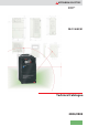
MITSUBISHI ELECTRIC Frequency Inverter FR-F 740 EC/E1 Technical Catalogue 2004/2005
The new FR-F 740 inverter series Saving r e w o P e h T Inverters The new FR-F 740 frequency inverters are available with outputs from 0.75 – 630 kW and are ideal for applications with pump and fan drives. They use a 3-phase AC power supply and have an output frequency range of 0.5 – 400 Hz.
CONTENTS FREQUENCY INVERTER FR-F 740 EC/E1 SYSTEM DESCRIPTION 웇 웇 웇 웇 웇 웇 Introduction to the FR-F740 series . . . . . . . . . . . . . . . . . . . . . . . . . . . . . . . . . . . . . . . . . . . . . . . . . . . . . . . . . . . . . . . . . . . . . . . . . 4 Energy conservation mode . . . . . . . . . . . . . . . . . . . . . . . . . . . . . . . . . . . . . . . . . . . . . . . . . . . . . . . . . . . . . . . . . . . . . . . . . . . . . . . 5 Control functions and communications . . . . . . . . . . . . . . . .
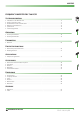
SYSTEM DESCRIPTION The FR-F 740 Frequency Inverter Mitsubishi Electric’s FR-F 740 series is a completely new range of frequency inverters with truly exceptional power conservation capabilities. These inverters are ideal for pumps, ventilation fans and applications with reduced overload requirements such as: Air conditioning systems, e.g.
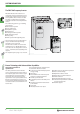
SYSTEM DESCRIPTION Intelligent Technology that Cuts Power Consumption Saving power with Mitsubishi frequency converters How do frequency inverters conserve energy? Reducing consumption and optimising the utilisation of our valuable energy resources is one of the greatest global environmental challenges of our age. Energy conservation mode is a standard feature of the intelligent controller.
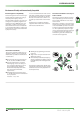
SYSTEM DESCRIPTION Intelligent Motor Control Functions Flow rate Extended PID control The FR-F 740 series supports extended PID control. This feature makes it possible to connect the process status signal to the frequency inverter as a voltage signal (0–10 V DC) or a current signal (0/4–20 mA DC) and then use the analog input calibration function of the inverter to compensate minor controller-related fluctuations. In addition to this the frequency inverter can also control up to four motors successively.
SYSTEM DESCRIPTION Innovative Features and Functions Flying start Magnetic flux vector control Regeneration avoidance function Gentle restart of a rotating motor (e.g. fan rotated by a draft), also in the opposite direction. The integrated motor flux vector control system makes it possible to achieve high torques, even at low motor speeds. PTC temperature sensor input Optimum excitation control The motor’s internal PTC temperature sensor can be connected to the inverter directly.
SYSTEM DESCRIPTION Extensive Communications Support Extended I/Os for additional control functions Support for integration in larger networks The following I/Os are included as standard equipment on the FR-F 740: 앬 12 contact inputs 앬 3 analog inputs 앬 5 open collector outputs 앬 2 relay outputs 앬 2 analog outputs The contact inputs, open collector outputs and relay outputs can all be used for a wide range of functions. Two of the analog inputs can be switched from current to voltage.
SYSTEM DESCRIPTION Environment-Friendly and Internationally Compatible Electromagnetic compatibility New technologies have been used to significantly reduce the interference levels generated by this frequency inverter. The FR-F 740 EC conforms to the strict electromagnetic compatibility regulations of the European Union (EMC Directive, Environment 2).
SYSTEM DESCRIPTION User-friendly Operation Easy configuration with control panel or software The FR-DU07 control panel is included as standard equipment with all the inverters of this series. It makes operation of the inverter simple and intuitive and displays operating parameters and alarm messages. The jog shuttle “digital dial” control provides fast and efficient access to all key drive parameters.
SYSTEM DESCRIPTION Long Service Life and Easy Maintenance New components for longer service life The components of this new generation of frequency inverters are specified for a service life of 10 years (mean annual ambient temperature 40°C, 80% load in an environment free of aggressive gases, flammable gases, oil mist, dust and dirt). Among other things, this is made possible by the newly-developed, long-life cooling fans that are monitored by the inverter.
SYSTEM DESCRIPTION Specifications FR-F 740-00023 to -01160 Rated motor capacity [kW] 120% overlaod capacity 햶 0.75 1.5 2.2 3.7 5.5 7.5 11 15 18.5 22 30 37 45 55 150% overlaod capacity 1.5 2.2 3.7 5.5 7.5 11 15 18.5 22 30 37 45 55 I rated 햷 2.3 (2.0) 3.8 (3.2) 5.2 (4.4) 8.3 (7.1) 12.6 (10.7) 17 (14.5) 25 (21.3) 31 (26.4) 38 (32.3) 47 (40.0) 62 (52.7) 77 (65.5) 93 (79.1) 116 (98.6) I max.60 s 2.5 I max.3 s 2.8 4.2 5.7 9.1 13.9 18.7 27.5 34.1 41.8 51.
SYSTEM DESCRIPTION Specifications FR-F 740-01800 to -12120 Rated motor capacity [kW] 120% overlaod capacity 햶 90 110 132 160 185 220 250 280 315 355 400 450 500 560 630 150% overlaod capacity 90 110 132 160 185 220 250 280 315 355 400 450 500 560 I rated 햷 180 (153) 216 (184) 260 (221) 325 (276) 361 (307) 432 (367) 481 (409) 547 (465) 610 (518) 683 (581) 770 (654) 866 (736) 962 (818) 1094 (870) 1212 (1030) I max.60 s 198 I max.
SYSTEM DESCRIPTION Specifications Frequency setting resolution Analog input Digital input 0.015 Hz / 0–50 Hz (terminal 2,4:0–10 V / 12 bit) 0.03 Hz / 0–50 Hz / (terminal 2,4:0–5 V / 11 bit,0–20 mA / 11 bit,terminal 1:−10–+10 V / 11 bit) 0.06 Hz / 0–50 Hz (terminal 1:0–±5 V / 10 bit) 0.01 Hz Frequency accuracy ±0.2% of the maximum output frequency (temperature range 25° ± 10°C) via analog input; ±0.
SYSTEM DESCRIPTION General Operating Conditions Ambient temperature in operation −10°C to +50°C (non-freezing) For selection of the load characteristics with a 120% overload rating the max.temperature is 40°C. Storage temperature* −20 to +65°C Ambient humidity Max.90% RH (non-condensing) Altitude Max.1000 m above NN Shock resistance 10 G (3 times each in 3 directions) Vibration resistance Max.0.
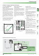
SYSTEM DESCRIPTION CN8* N/- PX PR P1 P/+ Block Diagram Intermediate circuit connections U V W L1 L2 L3 3phase AC power supply Control circuit mains supply connection Motor L11 L21 ON *The CN8 connector is provided with the inverter 01800 or more.
SYSTEM DESCRIPTION Terminal Assignment of Signal Terminals STF Forward rotation start STR Reverse rotation start The motor rotates reverse,if a signal is applied to terminal STR. STOP Start self-retaining selection The start signals are self-retaining,if a signal is applied to terminal STOP. Multi-speed selection Preset of 15 different output frequencies JOG Jog mode selection The JOG mode is selected,if a signal is applied to terminal JOG (factory setting).
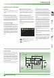
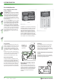
CONTROL PANELS Built-in Operation Panel FR-DU07 (Standard) Shows that the frequency inverter is in operation Selected operating mode Four-digit 7-segment display for operating parameters,error codes and other functions 8.8.8.8. Operating mode selector 앫PU:Operation via panel keys 앫EXT:Operation via external signals Hz A V MON P.
CONTROL PANELS Control Panel FR-PU04 (Option) The control panel FR-PU04 with extended functions is available as optional accessory. This control panel provides a 10-key keypad for a direct entering of numerical values. A 4-row LC display returns operational data, parameter names or status and error messages in uncoded text. The control panel displays text in the following selectable languages: English, German, French, Spanish, Swedish, Italian, Finnish, and Japanese.
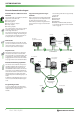
CONTROL PANELS Operating Modes Q1 Sample connection The inverter can alternatively be operated via external signals or directly via the operation panel FR-DU07 or the control panels FR-PU04. On the FR-DU07 control panel the operating mode is selected by pressing the PU/EXT key. On the FR-PU04 the EXT key selects operation by external signals and the PU key selects operation via the control panel. FR-F 740 EC Mains These connections are required for combined operation or operation by external signals.
CONTROL PANELS VFD Setup Software The VFD Setup Software is a powerful tool for the operation of your frequency inverter. The software (version 2.4) is MS Windows 95/98/ME/XP and NT/2000 compatible, and therefore allows the inverter operation via any conventional personal computer. Several frequency inverters can be set up, operated, and monitored simultaneously across a network or via a personal computer or notebook.
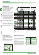
PARAMETER Parameter Overview 22 0–30% 6 / 4 / 3 / 2 / 1.5 / 1% 햳 Maximum frequency 0–120 Hz 120 / 60 Hz 햳 2 Minimum frequency 0–120 Hz 0 Hz 3 Base frequency 0–400 Hz 50 Hz 4 1. Multi-speed setting (high speed) 햲 0–400 Hz 50 Hz 0–400 Hz 30 Hz 0 Torque boost 1 5 2. Multi-speed setting (middle speed) 6 3.
PARAMETER 52 DU/PU main display data selection 햲 54 CA terminal function selection 햲 55 Frequency monitoring reference 56 Current monitoring reference 햲 57 햲 0 / 5 / 6 / 8–14 / 17 / 20 / 23 / 24 / 25 / 50–57 / 100 햴 0 1–3 / 5 / 6 / 8–14 / 17 / 21 / 24 / 50 / 52 / 53 햴 1 0–400 Hz 50 Hz 0–500 A / 0–3600 A 햳 Rated current Restart coasting time 0 / 0.1–5 s / 9999 / 0 / 0.
PARAMETER 130 PID integral time 햲 131 132 133 PID action set point 햲 0.1–3600 s / 9999 1s PID upper limit 0–100% / 9999 9999 PID lower limit 0–100% / 9999 9999 햲 0% 0.01–10.00 s / 9999 9999 134 PID differential time 135 Power-supply switchover sequence output terminal selection 0/1 0 136 MC switchover interlock time 0–100 s 1s 137 Waiting time at a start 0–100 s 0.
PARAMETER 184 AU terminal function selection 185 JOG terminal function selection 5 186 CS terminal function selection 6 187 MRS terminal function selection 188 STOP terminal function selection 25 189 RES terminal function selection 62 190 RUN terminal function selection 0 191 SU terminal function selection 192 IPF terminal function selection 193 OL terminal function selection 194 FU terminal function selection 195 ABC1 terminal function selection 196 ABC2 terminal function sel
PARAMETER 332 RS-485 communication speed 333 RS-485 communication stop bit length 334 RS-485 communication parity check selection 335 RS-485 communication number of retries 0–10 / 9999 1 336 RS-485 communication check time interval 0–999.
PARAMETER 0–3600 s / 9999 5 s / 15 s 햳 AM output filter 0–5 s 0.
PROTECTIVE FUNCTIONS Protective Functions Overview The frequency inverter FR-F 740 provides a large number of protective functions that protect the drive and the inverter against damage in case of any malfunction. HOLD 햲 Operation panel lock Operation lock mode ist set. Press and hold the MODE key for 2 s to enable the operation panel. Er1 햲 Write disable error This error occurs when a write operation is attempted with Pr.
PROTECTIVE FUNCTIONS E.OC1 Overcurrent 1 (acceleration) E.OC2 Overcurrent 2 (const.speed) E.OC3 Overcurrent 3 (deceleration) E.OV1 Overvoltage 1 (acceleration) E.OV2 Overvoltage 2 (constant speed) E.OV3 Overvoltage 3 (deceleration) E.
PROTECTIVE FUNCTIONS E.PUE PU disconnection A connection error between inverter and control panel occurred during operation.This alarm is only Check the connection of control panel. returned,if parameter 75 is set to “2",”3",“16",or ”17". E.RET Retry count excess After activation of a protective function the inverter failed to be restarted automatically within the number of retries specified in parameter 67. Remedy the actual cause of the originary protective function. E.CPU CPU error E.
PROTECTIVE FUNCTIONS Resetting Methods When a protective function is activated, the output of the inverter is switched off. The motor coasts to a halt. The output remains switched off until the error cause is eliminated and the inverter reset. The inverter can be reset following four different methods: If on occurrence of an error the input protection contactor is toggled the error message cannot be retained, since there is no power supply for the control circuit.
APPLICATIONS Application Examples Ventilation system Ventilation systems of modern painting plants often have high-powered motors. This makes them an ideal application for frequency inverters, which can replace the contactors and “soft starter” systems with bypass circuits that are often used in these installations. The higher initial investment involved in installing frequency inverters can pay for itself in a very short time because of the many benefits of this solution.
APPLICATIONS Stamping press (small metal parts production) Retrofitting this stamping press with the FR-F 740 frequency inverter brought significant energy savings. The secret is the FR-F 740’s intelligent Flux Optimisation mode. During the phase of the stamping sequence with low overload requirements Flux Optimisation mode quickly reduces the motor voltage. Die kurze Regelzeit der Flux-Optimisation ist der Schlüssel zum Erfolg: Die Spannung wird für den nächsten Stanz-Vorgang wieder angehoben.
ACCESSORIES Internal and External Options D199K3C FG The internal options comprise input and output extensions as well as communications options supporting the operation of the inverter within a network or connected to a personal computer or PLC. ECHELON FTT-10A 50051 T0121B Interface for the input of the frequency setting via 4-digit BCD or 16-bit binary code,setting of gain and bias supported.
ACCESSORIES External Options In addition to the FR-PU04 control panel that enables interactive operation of the frequency inverter the available external options also include additional EMC noise Control panel (8 languages) Connecting cable for remote control panel filters, reactors for improving efficiency and brake units with brake resistors. FR-PU04 FR-A5 CBL 67735 Refer to p.18 for detailed descriptio Cable for a remote connection of the control panel FR-DU07 or FR-PU04. Available length:1; 2.
ACCESSORIES 왎 Noise Filters for FR-F 740-00023 to FR-F 740-01160 Environment 1 noise filters L1 L2 L3 E L1’ L2’ L3’ E The noise filters listed below make it possible to comply with the requirements for Environment 1 (unrestricted distribution) with shielded motor cables up to 20m long and the requirements of Environment 1 (restricted distribution) with shielded motor cables up to 100m long. This also provides compliance with the 100A limits for Environment 2 with shielded cables up to 100m long.
ACCESSORIES 왎 DC Reactors DC link reactors A DC link reactor is included as standard equipment with frequency inverter models FR-F740-01800 and above. This reactor is essential for the operation of the inverter and must be installed. The reactors listed below are available as optional equipment for frequency inverter models FR-F740-00023 through 01160.
ACCESSORIES 왎 Brake Unit MT-BU5 The MT-BU5 external brake units can be used with frequency inverter models FR-F740-01800 and above. These inverters are fitted with a connector via which the MT-BU5 brake unit is controlled directly. This connection also makes it possible for the FR-F740 to handle the protection of the MT-BU5 against thermal overloads. FREQROL 400V series Brake resistors must be chosen in accordance with your application’s requirements.
ACCESSORIES 왎 Brake Units BU-UFS For a braking torque higher than 20% or a duty cycle higher than 30% an external brake unit including the adequate brake resistors has to be installed. The brake units BU-UFS listed below are cascadable so that the optimum dimensioning can always be achieved. FR-F740-00023 – 00250 BU-UFS22 FR-F740-00250 – 00470 BU-UFS40 FR-F740-00470 – 01160 BU-UFS110 The brake units here are not fitted with brake resistors, which must be ordered separately (see below).
DIMENSIONS 왎 Operation panel FR-DU07 Switchgear 6 22 44 21 50 44 3 Max.
DIMENSIONS 7,5 왎 FR-F 740-00023 – 00126 6 125 150 140 5 45,5 Note: Models 00023 through 00052 do not have internal fans. 7,5 245 260 2 – ø6 144 All dimensions in mm 7,5 왎 FR-F 740-00170 – 00380 6 195 7,5 B B1 2 – ø6 10 C FR-F740-00170, FR-F740-00250 260 245 170 84 FR-F740-00310, FR-F740-00380 300 285 190 101.
10 DIMENSIONS 왎 FR-F 740-00470 – 00620 10 380 400 2 – ø10 10 10,5 230 250 101,5 190 250 왎 FR-F 740-00770 – 01160 B 550 B1 2 – ød All dimensions in mm 3,2 10 A2 A1 C A FR-F740-00770 325 270 10 530 10 195 10 FR-F740-00930, FR-F740-01160 435 380 12 525 15 250 12 42 FR-F 740 EC/E1 All dimensions in mm MITSUBISHI ELECTRIC
DIMENSIONS B1 B 15 2 – ø12 왎 FR-F 740-01800 – 02160 3,2 10 A2 A1 C A FR-F740-01800 435 380 12 550 525 250 FR-F740-02160 465 400 32,5 620 595 300 All dimensions in mm 15 왎 FR-F 740-02600 – 03610 B1 B 2 – ø12 FR-F740-02600 595 620 300 FR-F740-03250, FR-F740-03610 715 740 360 MITSUBISHI ELECTRIC 3,2 10 400 465 C All dimensions in mm FR-F 740 EC/E1 43
DIMENSIONS B2 왎 FR-F 740-04320 – 08660 A2 A1 B2 B1 B 3 - ø12 A1 3,2 C A All dimensions in mm 984 13 380 1010 984 13 380 1330 1300 15 440 FR-F740-04320 – FR-F740-04810 498 200 49 1010 FR-F740-05470 – FR-F740-06830 680 300 40 FR-F740-07700 – FR-F740-08660 790 315 80 44 FR-F 740 EC MITSUBISHI ELECTRIC
DIMENSIONS 15 왎 FR-F 740-09620 – 12120 47,5 300 300 300 15 1550 1580 4 - ø12 3,2 440 995 MITSUBISHI ELECTRIC FR-F 740 EC/E1 45
DIMENSIONS 왎 Special Noise Filters FFR-A540-8A-SF100 to FFR-A540-180A-SF100 4 x ∅G C A FFR-A540-8A-SF100 B B C 8 x ∅ M5 A D D 150 260 315 50 1.5 FFR-F740-55A-SF100 00310/00380 221.5 300 360 80 M5 3 FFR-A540-16A-SF100 00083 150 260 315 50 1.5 FFR-A540-75A-SF100 00470/00620 251.5 400 476 80 M5/M8 4.1 FFR-A540-30A-SF100 00126–00250 220 260 315 60 1.8 FFR-A540-95A-SF100 00770 340 550 626 90 M8 6.7 FFR-A540-120A-SF100 00930 450 550 636 120 M10 9.
DIMENSIONS 왎 Converter Choke FR-HEL-H90K FR-HEL-H90K 150 130 340 310 190 20 B B1 All dimensions in mm ? A1 A C 왎 Converter Choke FR-HEL-H110K – 160K FR-HEL-H110K 150 130 340 310 195 M6 M6 22 FR-HEL-H132K 175 150 405 370 200 M8 M6 26 FR-HEL-H160K 175 150 405 370 205 M8 M6 28 A1 B B1 All dimensions in mm S A C S1 왎 Converter Choke FR-HEL-H185K – 355K FR-HEL-H185K 175 150 405 370 240 M8 M6 – M12 29 FR-HEL-H220K 175 150 405 370 240 M8 M6 M6
DIMENSIONS 왎 Converter Choke FR-HEL-H400K – 450K 2 - M8 FR-HEL-H400K 235 250 50 FR-HEL-H450K 240 270 57 All dimensions in mm 500±10 455±10 4 - ø15 û÷ e 75 40 C 195 4 - M10 220 C A 왎 Converter Choke FR-HEL-H500K – 630K 40 4 - ø15 FR-HEL-H500K 345 455 405 67 FR-HEL-H560K 360 460 410 85 FR-HEL-H630K 360 460 410 95 All dimensions in mm M12 75 245 40 P P1 B 2 - M12 150 M10 215 48 FR-F 740 EC C1±10 C±10 MITSUBISHI ELECTRIC
DIMENSIONS 왎 Brake Units MT-BU5 A P & PR n x M6 B B’ A’ NP MT-BU5-H75K 118 90 200 100 256.5 1.5 MT-BU5-H150K 188 160 200 100 256.5 3.0 MT-BU5-H220K 258 230 200 100 256.5 4.5 MT-BU5-H280K 328 300 200 100 256.5 6.0 MT-BU5-H375K 398 370 200 100 256.5 7.5 All dimensions in mm TM 4 - 7 x 10 C 왎 Brake Units BU-UFS C A A' BU-UFS22 100 50 250 240 175 2.5 BU-UFS40 100 50 250 240 175 2.5 BU-UFS110 107 50 250 240 195 3.
ORDER FORM Company: . . . . . . . . . . . . . . . . . . . . . Department: . . . . . . . . . . . . . . . . . . . . . Pos. Number Item (type) Article number Street: . . . . . . . . . . . . . . . . . . . . . Address: . . . . . . . . . . . . . . . . . . . . . Phone: . . . . . . . . . . . . . . . . . . . . . Fax: . . . . . . . . . . . . . . . . . . . . . Description Remarks Notes when ordering: When ordering, please use only the type designations and order numbers shown in this catalogue.
INDEX A Application examples . . . . . . . . . . . . . . . . . . . . . . . . . . . 32 I Internal options. . . . . . . . . . . . . . . . . . . . . . . . . . . . . . . 34 B Block diagram. . . . . . . . . Brake resistors Dimensions . . . . . . . . for Brake unit BU-UFS . for Brake unit MT-BU . . Brake units Description BU-UFS . . . Description for MT-BU5 Dimensions . . . . . . . . L Long service life . . . . . . . . . . . . . . . . . . . . . . . . . . . . . . 11 . . . . . . . . . . . . . . . . . . . . . .
HEADQUARTERS EUROPEAN REPRESENTATIVES EUROPEAN REPRESENTATIVES EURASIEN REPRESENTATIVES MITSUBISHI ELECTRIC EUROPE EUROPE B.V. German Branch Gothaer Straße 8 D-40880 Ratingen Phone: +49 (02102 / 486-0 Fax: +49 (02102 / 4 86-11 20 E-Mail: megfamail@meg.mee.com MITSUBISHI ELECTRIC FRANCE EUROPE B.V. French Branch 25, Boulevard des Bouvets F-92741 Nanterre Cedex Phone: +33 1 55 68 55 68 Fax: +33 1 55 68 56 85 E-Mail: factory.automation@fra.mee.com MITSUBISHI ELECTRIC IRELAND EUROPE B.V.