
User's Manual

3 - 66
3. SIGNALS AND WIRING
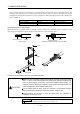
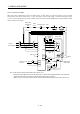
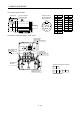
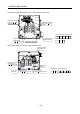
3.13.2 Servo amplifier terminals
The positions and signal arrangements of the terminal blocks change with the capacity of the servo
amplifier. Refer to section 11.1.
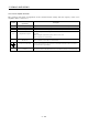
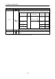
Symbol
Connection Target
(Application)
Description
L
1
, L
2
, L
3
Main circuit power supply Supply L
1
, L
2
and L
3
with three-phase 200 to 230VAC, 50/60Hz power.
U, V, W Servo motor output Connect to the servo motor power supply terminals (U, V, W).
L
11
, L
21
Control circuit power supply Supply L
11
and L
21
with single-phase 200 to 230VAC power.
P, C Regenerative option
The servo amplifier built-in regenerative resistor is not connected at the time of
shipment.
When using the regenerative option, wire it across P-C.
Refer to section 13.1.1 for details.
N
Return converter
Brake unit
When using the return converter or brake unit, connect it across P-N.
Refer to sections 13.1.2 and 13.1.3 for details.
Protective earth (PE)
Connect this terminal to the protective earth (PE) terminals of the servo motor
and control box for grounding.
P
1
, P
Power factor improving DC
reactors
P
1
-P are connected before shipment. When connecting a power factor improving
DC reactor, remove the short bar across P
1
-P. Refer to section 13.2.4 for details.