
User's Manual

3 - 11
3. SIGNALS AND WIRING
3.3 I/O signals
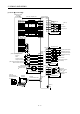
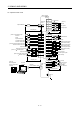
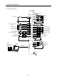
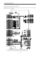
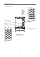
3.3.1 Connectors and signal arrangements
POINT
The pin configurations of the connectors are as viewed from the cable
connector wiring section.
Refer to (2) CN1A and CN1B signal assignment for CN1A and CN1B
signal assignment.
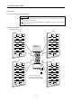
(1) Signal arrangements
(a) MR-J2S-700A or less
1
2
3
5
4
6
7
9
8
10
11
12
13
14
15
16
17
18
19
20
RXD
MO1
TRE
LG
LG
RDP
SDP
TXD
MO2
P5
LG
LG
RDN
SDN
1
2
3
5
4
6
7
9
8
10
11
12
13
14
15
16
17
18
19
20
1
2
3
5
4
6
7
9
8
10
11
12
13
14
15
16
17
18
19
20
1
2
3
5
4
6
7
9
8
10
11
12
13
14
15
16
17
18
19
20
MD
LG
MDR
P5
LG
MRR
P5
LG
P5
BAT
MR
LG
MITSUBISHI
MELSERVO-J2
CN2 CN3
CN1
A
CN1B
The connector frames are
connected with the PE (earth)
terminal inside the servo amplifier.