DLP™ PROJECTOR MODEL HC7800D HC7800DW User Manual HC7800D HC7800DW This User Manual is important to you. Please read it before using your projector.
CAUTION RISK OF ELECTRIC SHOCK DO NOT OPEN CAUTION: TO REDUCE THE RISK OF ELECTRIC SHOCK, DO NOT REMOVE COVER (OR BACK) NO USER-SERVICEABLE PARTS INSIDE REFER SERVICING TO QUALIFIED SERVICE PERSONNEL. The lightning flash with arrowhead symbol within an equilateral triangle is intended to alert the user to the presence of uninsulated “dangerous voltage” within the product’s enclosure that may be of sufficient magnitude to constitute a risk of electric shock.
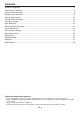
Contents Important safeguards.........................................................................................................................4 Preparing your projector.....................................................................................................................6 Using the remote control....................................................................................................................9 Setting up your projector..................................................
Important safeguards Please read all these instructions regarding your projector and retain them for future reference. Follow all warnings and instructions marked on the projector. 10. Power sources This projector should be operated only from the type of power source indicated on the marking label. If you are not sure of the type of power, please consult your appliance dealer or local power company. 11.
Important safeguards (continued) WARNING: Do not use the projector with condensation on it. It can lead to breakdown or other failure. Place of installation For safety’s sake, refrain from setting the projector at any place subjected to high temperature and high humidity. Please maintain an operating temperature, humidity, and altitude as specified below.
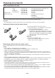
Preparing your projector What’s included in the box AC power cord* for US for EU for UK for Australia for South Korea Computer cable Mini DIN 5-pin cable J2552-0063-03 J2552-0247-00 J2552-0065-02 J2552-0053-00 J2552-0247-00 J2552-0072-05 J2552-0376-00 Remote control User Manual/Quick Start up (English only) Safety Manual/Quick Start up CD-ROM (with User Manual) Battery (2) Lens cap Lamp replacement attachment 3D emitter Non-slip sheet 3D emitter securing screw (2) * One of power cords for the U.S.
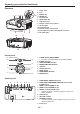
Preparing your projector (continued) Overview 1 2 34 5 7 6 9 8 10 1 2 3 4 5 6 7 8 9 10 11 12 13 Lamp cover Lens FOCUS ring ZOOM ring Control panel LENS SHIFT dial Adjustment feet Remote control sensor (front) Air inlet grille Terminal panel Remote control sensor (rear) Kensington Security Lock Standard connector Air outlet grille 11 12 13 Control panel 1 2 6 7 3 8 4 5 9 1 POWER button (ON/STANDBY) • The status is changed between ON and STANDBY.
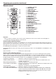
Preparing your projector (continued) Remote control 1 2 3 4 5 6 7 14 15 16 17 8 9 10 11 12 13 18 19 20 21 22 23 24 1 2 3 4 5 6 7 8 9 10 11 12 13 14 15 16 17 18 19 20 21 22 23 24 STANDBY ( ) button ON ( I ) button COMPUTER button HDMI 1/2 button PICTURE MODE button F.R.C. button AV MEMORY buttons p, q, t, u buttons MENU button CONTRAST button BRIGHTNESS button GAMMA button BRILLIANT COLOR button 3D MODE button COMPONENT button COLOR MANAGEMENT button ENTER button IRIS button ASPECT button COLOR TEMP.
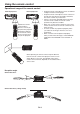
Using the remote control Operational range of the remote control Front of projector 30° Rear of projector 30° 30° 30° Operate the remote control within a distance of 10 m (30 feet) from the projector, pointing the IR beam at the remote control photo-sensor (front or rear) of the projector. • Keep the remote control photo-sensor out of direct sunlight or fluorescent lamp light. • Keep the remote control photo-sensor at least 2 m (6 feet) away from fluorescent lamps.
Setting up your projector Setting up the screen Install the screen perpendicularly to the projector. If the screen can not be installed in such a way, adjust the projection angle of the projector. (See page 12.) • Install the screen and projector so that the projector’s lens is placed at the same height and horizontal position of the screen center. • Do not install the screen where it is exposed to direct sunlight or lighting.
Setting up your projector (continued) Screen size and projection distance (continued) Screen width (SW) Screen height (SH) Screen H1 H2 Hd Down side Up side L When the aspect ratio of the screen is 4:3 SW (=W) B When the aspect ratio of the screen is 4:3, the positional relation between the projected image and the screen is as shown on the right. Refer to the following table for installation.
Setting up your projector (continued) Adjusting the position of the projected image To adjust the position of the projected image on the screen, use the LENS SHIFT dial. 1. Rotate the LENS SHIFT dial inside the top cover of the projector to adjust the image position. • Rotating the dial clockwise (or counterclockwise for a ceiling-mount projector) moves the image up. • Rotating the dial counterclockwise (or clockwise for a ceiling-mount projector) moves the image down.
Setting up your projector (continued) Front projection, ceiling mounting For ceiling mounting, you need the ceiling mount kit designed for this projector. Ask a specialist for installation. For details, consult your dealer. • The warranty on this projector does not cover any damage caused by use of any non-recommended ceiling mount kit or installation of the ceiling mount kit in an improper location.
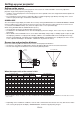
Viewing video images A. Connecting the projector to video equipment • When the projector and the connected devices are located too close to each other, the projected image may be affected by their interference. • See the owner’s guide of each device for details about its connections. Preparation: • Make sure that the power of the projector and that of the video equipment are turned off.
Viewing video images (continued) Connecting to a DVD player or HDTV decoder To connect this projector to video equipment that has component video output terminals, such as a DVD player, use the COMPONENT VIDEO IN terminals. Y Component cable (option) Y PR/CR PB/CB PR/CR PB/CB Y DVD player or HDTV decoder • • • • The terminal’s names Y, PB, and PR are given as examples of when a HDTV decoder is connected. The terminal’s names vary depending on the connected devices.
Viewing video images (continued) Connecting to video equipment having a HDMI terminal You can project high-quality images by connecting the HDMI 1 or HDMI 2 terminal of this projector to video equipment having a HDMI output terminal. In addition, this projector supports HDCP and is able to receive encrypted digital video data that are output from DVD players. • Select HDMI as the input source.
Viewing video images (continued) B. Plugging in the power cord • In order to ensure the safety in case of trouble with the projector, use an electrical outlet having an earth leakage breaker to supply the power to the projector. If you do not have such outlet, ask your dealer to install it. 1. Plug the attached power cord into the power cord inlet of this projector. 2. Plug the other end of the power cord into a power outlet. Earthing terminal 2 1 Power cord (example) • One of power cords for the U.S.
Viewing video images (continued) C. Projecting images Preparation: • Remove the lens cap. • Turn on the power of the connected video equipment. ON ( I ) button HDMI 1/2 button POWER button POWER indicator COMPONENT button STATUS indicator , buttons HDMI/COMPUTER button COMPONENT button 1. Confirm the POWER indicator lights-up red.
Viewing video images (continued) To stop projecting: STANDBY ( ) button POWER button POWER indicator STATUS indicator 9. Press the POWER button on the projector or the STANDBY ( ) button on the remote control. • A confirmation message is displayed. • To cancel the procedure, leave the projector for a while or press the MENU button. 10.Press the POWER button on the projector or the STANDBY ( ) button on the remote control again. • The lamp goes out and the projector goes into a standby mode.
Viewing video images (continued) Setting the aspect ratio You can change the aspect ratio of the input video signal (or the ratio of width to height of the image). Change the setting according to the type of the input video signal. : Signal size : Image area Setting 4:3 Aspect ratio changes depending on the input signal. Original image size 16:9 ZOOM1 ZOOM2 STRETCH Squeezed image is expanded to 16:9. CinemaScope image is enlarged and displayed together with subtitles.
Viewing video images (continued) How to change the settings: With the remote control: 1. Press the ASPECT button or ANAMO button. • Every time the ASPECT button is pressed, the aspect mode changes from AUTO to 4:3, 16:9, to ZOOM1, to ZOOM2, to STRETCH, and back to AUTO. • Every time the ANAMO button is pressed, the aspect mode changes from ANAMORPHIC1 to ANAMORPHIC2 and back to ANAMORPHIC1. • Some modes are not available with certain signals. With the FEATURE menu: (See page 29 for menu setting.) 1.
Viewing computer images A. Connecting the projector to a computer Preparation: • Make sure that the power of the projector and that of the computer are turned off. • When connecting the projector to a desktop computer, disconnect the computer cables that are connected to the monitor. 1. Connect one end of the supplied computer cable to the COMPUTER/COMPONENT VIDEO IN terminal of the projector. To COMPUTER/ COMPONENT VIDEO IN 2.
Viewing computer images (continued) C. Projecting images Preparation: • Remove the lens cap. • Turn on the power of the connected computer. ON ( I ) button POWER button POWER indicator COMPUTER button STATUS indicator , buttons HDMI/COMPUTER button 1. Confirm the POWER indicator lights-up red. • If the projector was turned off before the lamp had cooled down sufficiently, the fan may start rotating and the POWER button may not work after the power cord is plugged. (The STATUS indicator blinks green.
Viewing computer images (continued) To stop projecting: 9. Press the POWER button on the projector or the STANDBY ( ) button on the remote control. • A confirmation message is displayed. • To cancel the procedure, leave the projector for a while or press the MENU button. 10.Press the POWER button on the projector or the STANDBY ( ) button on the remote control again. • The lamp goes out and the projector goes into a standby mode. In this standby mode, the STATUS indicator blinks green. 11.
Viewing 3D images Important: • Do not put any object which obstructs the communication between the 3D emitter and the 3D glasses. • Do not place the 3D emitter near the remote control sensor of other devices. • The transmission distance is decreased when the infra-red signal from the 3D emitter is transmitted to the 3D glasses by reflecting on the screen. In addition, the transmission distance in such case varies depending on the characteristics of the screen.
Viewing 3D images (continued) 3D images viewing 3. Press the p or q button to select the desired item and press the t or u button to select the desired option. This projector is able to display the following 3D display supporting broadcasts and signals as stereoscopic images. (As of January, 2011) • 3D images input from the recorder/player supporting 3D display. (Side by side, top and bottom, and frame packing) • 3D images by the digital terrestrial broadcasting and BS digital broadcasting.
Viewing 3D images (continued) Important: • If the viewing distance is nearer than the recommended distance, it will cause physical discomfort and eye fatigue. • The 3D glasses may not work properly when it is used too far from the screen. • Watch the contents in front of the screen, not at big angle. If you are viewing the screen at big angle, you may not be able to view 3D contents correctly. • There are personal differences in viewing the 3D images.
Menu operation You can make various settings using the displayed menus. IMAGE PICTURE MODE GAMMA MODE CONTRAST BRIGHTNESS COLOR TEMP. COLOR TINT SHARPNESS *1 BrilliantColor™ 3D ADVANCED MENU CINEMA, VIDEO, 3D, ISF(DAY), ISF(NIGHT), AV MEMORY1 , AV MEMORY2 , AV MEMORY3 CINEMA, 2.0, 2.1(VIDEO), 2.2, 3D, 2.4 USER1 , USER2 ±30 ±30 HIGH BRIGHTNESS, COOL, MEDIUM, WARM, 3D USER ±10 ±10 ±5 ON, OFF ON OFF OK REFERENCE ADJUST MODE 2%, 4%, 6%, 10%, 15%, 20%, 25%, 30%, 40%, 50%, 70%, 90% 2.0, 2.1(VIDEO), 2.
Menu operation (continued) How to set the menus 5. Set the selected item by pressing the or button. 1. Press the MENU button. • The menu selection bar is displayed. opt. IMAGE Selectable menus are displayed by icons. (The menu icon being selected is displayed on a blue background.) PICTURE MODE GAMMA MODE opt. IMAGE The name of the menu being selected is displayed. CINEMA 0 0 COLOR TEMP. MEDIUM COLOR 0 TINT 0 0 ON OFF ADVANCED MENU OK 4.
Menu operation (continued) Menu items Set the following items provided in the respective menus. IMAGE menu opt. opt. IMAGE IMAGE PICTURE MODE ADVANCED MENU AV MEMORY1 GAMMA MODE SCREEN SIZE CINEMA CONTRAST 0 VERTICAL LOCATION BRIGHTNESS 0 FRAME RATE CONVERSION COLOR TEMP. MEDIUM F.R.C.
Menu operation (continued) IMAGE menu (continued) ITEM SETTING ADVANCED MENU OK 2 options SCREEN SIZE ±26 VERTICAL LOCATION FRAME RATE CONVERSION* OFF TRUE FILM TRUE VIDEO F.R.C. LEVEL* 1-5 AUTO IRIS* 4 options ON / OFF 0-5 AUTO ENHANCED NOISE REDUCTION* CTI* HDMI INPUT* NORMAL SUPERWHITE SETUP* AUTO OFF 3.75% / 7.5% COLOR MANAGEMENT* ON COLOR SPACE* WIDE / OFF NORMAL FUNCTION The ADVANCED MENU is displayed for the following settings. Select according to the screen size.
Menu operation (continued) INSTALLATION menu opt.
Menu operation (continued) FEATURE menu opt. FEATURE ASPECT AUTO DISPLAY INPUT PASSWORD FUNCTION MENU POSITION 1.
Menu operation (continued) SIGNAL menu opt. opt. SIGNAL R RG GB B VERT. POSITION 0 CLAMP POSITION FINE SYNC. 0 CLAMP WIDTH TRACKING 0 VERT. SYNC. COMPUTER INPUT AUTO LPF 1 1 AUTO OFF OVER SCAN 100% SHUTTER(U) 0 HOLD ON SHUTTER(L) 0 USER OK SHUTTER(LS) 0 SHUTTER(RS) 0 SETTING 0 - 999 0 - 999 0 - 31 TRACKING 0 - 9999 COMPUTER INPUT AUTO RGB YCBCR / YPBPR 100 - 90% OFF / ON HOLD USER OK CLAMP POSITION 1 - 255 CLAMP WIDTH 1 - 63 VERT. SYNC.
Menu operation (continued) NETWORK menu opt. opt. NETWORK NETWORK PROJECTOR NAME IP CONFIG NETWORK PASSWORD OK DHCP IP CONFIG OK IP ADDRESS 0. 0. 0. 0 PJLink CERTIFICATION ON SUBNET MASK 0. 0. 0. 0 NETWORK RESET OK DEFAULT GATEWAY MAC ADDRESS ITEM PROJECTOR NAME SETTING xxxxx... SET NETWORK PASSWORD OK IP CONFIG DHCP OK ON IP ADDRESS / OFF xxx. xxx. xxx. xxx SET SUBNET MASK xxx. xxx. xxx. xxx SET DEFAULT GATEWAY xxx. xxx. xxx.
Menu operation (continued) INFORMATION menu opt. INFORMATION 0H LAMP TIME(LOW) INPUT COMPUTER RESOLUTION 1024X768 VERTICAL FREQUENCY 75.04 Hz HORIZONTAL FREQUENCY 60.02 KHz SYNC. TYPE 5wire R G B H ITEM LAMP TIME(LOW) INPUT RESOLUTION VERTICAL FREQUENCY HORIZONTAL FREQUENCY SYNC. TYPE V DESCRIPTION This item shows a lamp operating time (hour) calculated based on that LAMP MODE is LOW. • When the LAMP MODE is STANDARD, this item shows a longer lamp operating time than the actual time.
Adjusting projected images (continued) To adjust the brightness (CONTRAST and BRIGHTNESS): You can make adjustments for the brightness of the projected image using the menu. (See page 29 for menu setting.) 1. Display the IMAGE menu. 2. Select CONTRAST or BRIGHTNESS by pressing the or button. 3. Adjust the selected item by pressing the or button. To cancel the menu: 4. Press the MENU button. CONTRAST Select to adjust the contrast of the image.
Adjusting projected images (continued) To adjust the tone of white (COLOR TEMP.): You can select a preset color temperature (white tone) using the menu. (See page 29 for menu setting.) 1. Display the IMAGE menu. 2. Select COLOR TEMP. by pressing the p or q button. 3. Select your desired color temperature by pressing the t or u button. The color temperature of each option is as follows: COOL: Approx. 9300K, MEDIUM: Approx. 6500K (D65), WARM: Approx. 5800K. To cancel the menu: 4. Press the MENU button.
Adjusting projected images (continued) To adjust the ratio of change in brightness (GAMMA MODE): You can select a preset gamma mode using the menu. (See page 29 for menu setting.) 1. Display the IMAGE menu. 2. Select GAMMA MODE by pressing the p or q button. 3. Select your desired gamma mode by pressing the t or u button. To cancel the menu: 4. Press the MENU button.
Adjusting projected images (continued) This projector automatically and properly projects video signals supplied from the computer. However, some video signals may not be projected, depending on the type of the computer. In such a case, press the AUTO POSITION button. (See page 24.) When the signal is still not projected properly, adjust the projected image using the SIGNAL menu. How to adjust the image supplied from the computer using the menu: Carry out the following procedures according to the symptoms.
Advanced features Password function To cancel the password function: 1. Display the FEATURE menu. 2. Press the p or q button to select PASSWORD FUNCTION. 3. Press the ENTER button. • The screen for canceling the password function will appear. This projector is equipped with the password function that is designed for prevention of theft and wrong operation by children and restriction on operation by other than specified users. The password function has two modes as follows. DISPLAY INPUT...........
Advanced features (continued) Supervising and controlling by computer · During auto position execution · During command processing · Before the splash screen disappears after the power is turned on. • Use 1 controller to control/monitor 1 projector. • For how to control/monitor using PJLink™, see the operation manual of the PJLink™ application you use.
Advanced features (continued) Connection For details of the connection, see “LAN control UTILITY operation manual” in the CD-ROM. When STANDBY MODE of the INSTALLATION menu of the projector is set to LOW, the LAN network is disabled. To enable the LAN network, set STANDBY MODE to STANDARD. (See page 32.) Configure the initial network settings first. You can configure the initial settings using the projector menu (see pages 44 to 47) or ProjectorView Global+ or ProjectorView.
Initial network settings Network password settings You can set the network of the projector using the menu. (See page 29 for menu setting.) 1. Display the NETWORK menu. 2. Press the or button to select NETWORK PASSWORD. opt. NETWORK PROJECTOR NAME NETWORK PASSWORD OK IP CONFIG OK PJLink CERTIFICATION ON NETWORK RESET OK NETWORK PASSWORD 3. Press the ENTER button. • CURRENT NETWORK PASSWORD screen appears.
Initial network settings (continued) Setting or clearing DHCP 6. Enter the NEW NETWORK PASSWORD and CONFIRM NETWORK PASSWORD. • Password can be set using up to 32 characters including alphabets (capital/small) or numeric characters. ← key: ������������� Shifting the position of enter cursor to the left for each character. → key: ������������� Shifting the position of enter cursor to the right for each character.
Initial network settings (continued) 6. Select OK to complete the setting with the IP address stored. Select CANCEL to complete the setting without storing. • When the setting you entered is correct, the setting change dialog is displayed. After the dialog disappears, the NETWORK menu is displayed. If the entered content is not correct, the NETWORK menu is displayed after an error dialog is displayed. • It may take some time to reflect the settings.
Initial network settings (continued) How to use network function • When connecting a computer and projector with LAN, configure the both IP Addresses in the same network group. If connecting in different network group, be sure to use a router. As for the settings of a router, ask the network administrator. • Configure the IP CONFIG correctly. If the settings are not correct, the communication may be unavailable. For the detail, consult the network administrator.
Replacing the lamp This projector is equipped with a lamp to project images. This lamp is a consumable. It may burn out or its brightness may decrease during use. In such cases, replace the lamp with a new one as soon as possible. Be sure to replace the lamp with a new lamp sold separately that is exclusive to this projector. Contact your dealer for purchase of the lamp. Spare lamp VLT-HC7800LP Warning: • Be careful not to drop the lamp fixing screws inside of the projector.
Replacing the lamp (continued) To replace the lamp: A) When the projector is placed on the table B) When the projector is mounted to the ceiling When removing the lamp unit from the projector mounted to the ceiling, never fail to use the lamp replacement attachment to protect yourself from glass fragments and so on. • Contact your dealer when replacing the lamp unit with the projector mounted to the ceiling. 1.
Replacing the lamp (continued) Reset of the lamp operation time 4. Insert two lugs of the lamp replacement attachment into the slits (h) in the projector and fix the three taping portions (g) with the tape included in the lamp replacement attachment. Plug in the power cord, and reset the lamp operation time by keep pressing the , , and POWER buttons on the control panel at the same time. Important: • Unless these three buttons are pressed at the same time, the lamp operation time isn’t reset.
Maintenance Warning: • Do not use flammable solvents (benzene, thinner, etc.) and flammable aerosols when cleaning the projector body and lens. Flammable substances may ignite causing fire or breakdown while the lamp is illuminating. Caution: • Be sure to turn off the lamp and unplug the power cord from the wall outlet before you perform any maintenance on the projector. • Ask your dealer for annual cleaning of the inside of the projector.
Troubleshooting Before asking for repair of the projector, check the following. If the symptom persists, stop using the projector, be sure to unplug the power plug, and then contact your dealer. No image appears on the screen. Problem Solution Power can not be turned on. • Check whether the indicators are on or off and how they are lightning. POWER STATUS Solution • Connect the power cord to the projector. Off Off • Plug the power cord into a wall outlet.
Troubleshooting (continued) No image appears on the screen. (continued) Problem The screen for entering the password appears. “NO SIGNAL” is displayed. Images may be jagged when connecting the projector using the HDMI cable. “NO SIGNAL” is displayed when connecting the projector using the HDMI cable. Solution • PASSWORD FUNCTION in the FEATURE menu has been set to DISPLAY INPUT to enable the password lock. Enter the password or contact the person in charge of management of the projector. (See page 41.
Troubleshooting (continued) Images are not displayed correctly. (continued) Problem Solution Tint in projected images is incorrect. • Check that COMPUTER INPUT in the SIGNAL menu is correctly set. (See page 34.) • Check that the cable connected to the external device isn’t broken. • When comparing images projected by two projectors, tints in the displayed images may be different because of variation between their optical components. This is not a malfunction.
Troubleshooting (continued) Others (continued) Problem Solution The remote control doesn’t function easily or at all. • Check that the batteries are loaded in the remote control or the batteries are not weak. (See page 6.) • Check that the remote control sensor isn’t exposed to direct sunlight or fluorescent light. (See page 9.) • Use the remote control within its operation range. (See page 9.) • Use the remote control at least 10 cm away from the projector.
Troubleshooting (continued) Others (continued) Problem There is something wrong with the 3D images. * The 3D glasses are sold separately. They are not supplied with this product. The indicator on the 3D glasses does not light up even if the power is turned on. * The 3D glasses are sold separately. They are not supplied with this product. Solution • Depending on the 3D image status, you may feel something wrong with the 3D images. Switch the 3D SYNC.
Indicators This projector has two indicators, each of which shows the operation condition of the projector. The following offer solutions to possible problems. If these problem persist, turn the projector off and consult your dealer. POWER indicator STATUS indicator Normal condition POWER STATUS Off Steady red Blinking green Blinking green Steady green Steady green CONDITION NOTE Stand-by Lamp stand-by for power-off The power cannot be turned on by pressing the POWER button.
Specifications The specifications and outside appearance of the projector are subject to change without prior notice. Type DLP™ projector Model HC7800D/HC7800DW Display technology 0.65-inch single chip DMD (aspect ratio 16:9) Pixel: 1920 x 1080 = 2073600 pixels Projection lens F 2.4 - 2.8 f= 20.6 - 30.1 mm Light-source lamp 240 W Image size (projection distance) 50” min. to 300” max. (projection distance 1.5 to 9.3 m (max.
Specifications (continued) Specification of RGB signals in each computer mode of the projector Signal mode TV60, 480i (525i) TV50, 576i (625i) 1080i 60 (1125i 60) 1080i 50 (1125i 50) 480p (525p) 576p (625p) 720p 60 (750p 60) 720p 50 (750p 50) 1080p 60 (1125p 60) 1080p 50 (1125p 50) 1080p 24 (1125p 24) PC98 CGA70 VGA60 VGA72 VGA75 VGA85 SVGA56 SVGA60 SVGA72 SVGA75 SVGA85 XGA60 XGA70 XGA75 XGA85 MAC13 MAC16 MAC19 HP75 SXGA60 UXGA60 Resolution (H x V) – – – – – – – – – – – 640 x 400 640 x 400 640 x 480 640 x
Specifications (continued) Connectors COMPUTER/COMPONENT VIDEO IN (Mini D-SUB 15-pin) SERIAL (D-SUB 9-pin) 5 5 1 9 6 10 6 15 Pin No. Name I/O 1 – – 2 TXD IN 3 RXD OUT 4 – – 5 GND – 6 – – 7 – – 8 – – 9 – – 1 11 Pin No. Spec. 1 R(RED)/PR/CR 2 G(GREEN)/Y 1 19 2 18 3 B(BLUE)/PB/CB PIN No.
1 Zusho Baba, Nagaokakyo-City, Kyoto Japan Ver. 1.