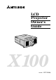
LCD Projector Owner's Guide X100 MODEL LVP-X100A 1
CAUTION RISK OF ELECTRIC SHOCK DO NOT OPEN CAUTION: TO REDUCE THE RISK OF ELECTRIC SHOCK, DO NOT REMOVE COVER (OR BACK) NO USER-SERVICEABLE PARTS INSIDE REFER SERVICING TO QUALIFIED SERVICE PERSONNEL. The lightning flash with arrowhead symbol, within an equilateral triangle, is intended to alert the user to the presence of uninsulated “dangerous voltage” within the product’s enclosure that may be of sufficient magnitude to constitute a risk of electric shock.
COMPLIANCE NOTICE OF FCC This equipment has been tested and found to comply with the limits for a Class A digital device, pursuant to Part 15 of the FCC Rules. These limits are designed to provide reasonable protection against harmful interference when the equipment is operated in a commercial environment. This equipment generates, uses, and can radiate radio frequency energy and, if not installed and used in accordance with the instruction manual, may cause harmful interference to radio communications.
Contents Important safeguards ........................................................................... 5 Overview of the projector ..................................................................... 8 Overview of the remote control .......................................................... 12 Battery installation ........................................................................................... 13 Preparing the projector for operation ................................................
Important safeguards PLEASE READ ALL THESE INSTRUCTIONS REGARDING YOUR LCD PROJECTOR AND RETAIN THEM FOR FUTURE REFERENCE. FOLLOW ALL WARNINGS AND INSTRUCTIONS MARKED ON THE LCD PROJECTOR. 1. Read instructions All the safety and operating instructions should be read before the appliance is operated. 2. Retain instructions The safety and operating instructions should be retained for future reference. 3. Warnings All warnings on the appliance and in the operating instructions should be adhered to. 4.
Important safeguards (continued) 9. Ventilation Slots and openings in the cabinet are provided for ventilation, ensuring reliable operation of the projector and to protect it from overheating. Do not block these openings or allow them to be blocked by placing the projector on a bed, sofa, rug, or bookcase. Ensure that there is adequate ventilation and that the manufacturer's instructions have been adhered to. 10.
WARNING: Unplug immediately if there is something wrong with your projector. Do not operate if smoke, strange noise or odor comes out of your projector. It might cause fire or electric shock. In this case, unplug immediately and contact your dealer. Never remove the cabinet. This projector contains high voltage circuitry. An inadvertent contact may result in an electric shock. Except as specifically explained in the Owner's Guide, do not attempt to service this product yourself.
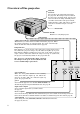
Overview of the projector lamp lid Caution: Do not replace the lamp right after using the projector. The lamp is very hot. Switch the projector to stand-by mode, wait at least 120 seconds for the lamp and LCD panel to cool. Then turn off the main power switch, unplug from the outlet and wait for another one hour or until the lamp is cool to the touch. exhaust slits handle Hold here to carry this projector. control panel temperature indicator This informs you of the thermal condition inside the projector.
FINE, ADJUST, FOCUS/ZOOM and AUTO buttons The operations of these buttons vary as follows depending on the modes selected: FINE ( Normal On Menu On PC card Menu Adjust FINE (-) FINE ( º ) Adjust FINE(+) ª FOCUS / ZOOM Adjust FOCUS or Adjust FOCUS or FOCUS or ZOOM ZOOM (-) ZOOM (+) setting AUTO Adjust position when incorrect Select the setting Select the setting Set or select the setting (Down) item (Left) item (Right) Set or select the setting (Up) Enter the layer setting – Select the image (
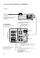
Overview of the projector (continued) Left side PC card eject Press to eject the PC card. See page 36. PC card insert slot This is where you insert the PC card. (You can insert up to two cards.) See page 36. PC audio input (stereo mini jack) Use to input PC audio signals. See pages 18~20. video/audio input Use to input video and audio. See page 21. PC analog RGB input (mini D-SUB 15P) Use to input RGB signal for PC. See pages 18~20.
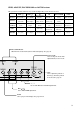
PC analog RGB input 5 1 Use to input video signals (analog RGB) of a personal computer. 6 10 (Pin assignment of Mini D-SUB 15P jack) PIN NO. 1 2 3 4 5 6 7 8 SPEC R(RED) / Cr G(GREEN) / Y B(BLUE) / Cb GROUND GROUND GROUND GROUND GROUND PIN NO. 9 10 11 12 13 14 15 15 SPEC GROUND GROUND HD/CS VD - RS-232C input • Connect here when you control this Projector with a personal computer using PCGC (personal computer graphic controller) or with a remote controller using SpacePointer function.
Overview of the remote control operation indicator When the operation button is pressed, this indicator blinks. When the PC mode or cursor operation mode is on, this indicator lights up. See pages 33, 45. select This operates in the same way as the left button on the computer mouse. See pages 33, 45. cancel This operates in the same way as the right button on the computer mouse. See pages 33, 45. start/stop Use to turn the PC control mode or cursor operation mode on or off. See pages 33, 45.
Important: • The select, double click, cancel and start/stop buttons are used for PC control. See page 45. • To save battery power, turn off the operation indicator by pressing the START/STOP button when not in use. • To save battery power, the operation indicator will turn off if the remote control is not operated for a period of 5 minutes. Battery installation Use two AA size batteries. 1. Remove the back cover of the remote control by pushing the battery compartment door in the direction of the arrow.
Preparing the projector for operation Orientation of the projector Picture size can be set by changing the distance between the screen and the projector. screen To find the approximate distance between the projector and screen: Multiply the width of the screen x 1.85 ⵑ 1.95 (max.) , Multiply the width of the screen x 2.33 ⵑ 2.53 (min.) , • Refer to the chart to recommended distaces in maximum zoom and minimum zoom.
Adjusting the angle of projection • Screen on a flat wall with a 90˚ angle to the floor. • Align projector to produce a full screen display as illustrated on page 14. • Distance from projector to screen must be compatible with screen size chart on page 14. Note distance from screen chart. • If image is not square on screen, try adjusting the front feet of the projector for proper angle. screen foot adjustment Getting ready for projection 1.
Basic connections This projector can be connected to equipment such as VCRs, video cameras, videodisc players, and personal computers having analog RGB input. Important: • Make sure that your equipment is turned off before connection. • Match the color of video and audio plugs on the AV cable with each terminal. • Plug in firmly and unplug by holding the plug, not by pulling the cable out. • If connected units are set too close to one another, the image may be affected.
Order of turning on / off Turn on equipment in the following order to avoid trouble. 1. PC monitor 2. AV equipment 3. Projector 4. Personal computer Turn off the equipment in the reverse order. Important: Some computers may not be compatible with this projector. Cables and adapters To connect personal computers to this projector, the following cables and adapters are necessary. The overview might be different from the picture below. RGB cables (mini D-SUB 15P plug) PIN NO. 1 2 3 PIN NO.
Basic connections (continue) Projector + IBM PC or IBM PC compatibles (DOS) Make sure that your equipment is turned off before connection. Important: • Connectors or analog RGB output adapters may be necessary depending on the personal computer connected to this projector. Please contact your dealer. • The audio input for a personal computer is the stereo mini-jack. There are some personal computers that have different types of audio outputs or none at all. Please ask your dealer for details.
Projector + Macintosh Make sure that your equipment is turned off before connection. Important: • A monitor output adapter is necessary for a Macintosh if it has no video port. Contact your dealer. • If you use the RGB conversion adapter provided, set the dip switch to the appropriate position. See page 17. • Connectors or analog RGB output adapters may be necessary depending on the personal computer connected to this projector. Please contact your dealer.
Basic connections (continue) Projector + NEC PC-98 and EPSON PC series Make sure that your equipment is turned off before connection. Important: • Connectors or analog RGB output adapters may be necessary depending on the personal computer connected to this projector. Please contact your dealer. • The audio input for a personal computer is the stereo mini jack. There are some personal computers that have different type or no audio outputs. Please ask your dealer for details.
Projector + AV equipment Make sure that your equipment is turned off before connection. Important: S-video signals take priority over video signals. If you input both S-video signals and normal video signals at the same time, the normal video input automatically shuts off. to audio input 2 to S-video input 2 to video input 2 to audio input 1 to S-video input 1 to video input 1 Connect either one of these. Connect either one of these.
To operate projector power ON Numbers 1~10 correspond to the instruction numbers below. 1, 10 Left side INPUT 1 PC-1 IN PC-AUDIO INPUT 2 MAIN AUDIO L PC-1 OUT R AC IN VIDEO PC-2 IN 4 S-VIDEO RS-232C LINE-OUT LAMP TEMP CARD1 FREEZE EXPAND SOURCE /CAPTURE /PinP MENU CARD2 FOCUS /ZOOM AUTO FINE ENTER 3, 8, 9 4 7 6 5 AUTO button 1. Put the projector into standby mode by pressing the main power switch. The POWER indicator lights up red. 2.
4. Select the desired external input source by using the SOURCE button. The source changes in the sequence shown below: VIDEO1 (PC2) VIDEO2 (PC1) RGB1 RGB2 • The projector automatically selects the appropriate signal system. When the source is selected to RGB1 or RGB2 and the image is not in the right place, set to display as blightest signal as possible, then press the AUTO button. If the image is still not in the right place, refer to USER PRESETS on page 32.
Menu operation Several settings can be adjusted using Menu. There are 5 modes. You can also make adjustments using PCGC (personal computer graphic controller). See pages 42 ~ 44 for details. MENU layers HELP HELP By selecting the HELP, you can view the MENU layers on the screen. NORMAL See page 26. CONTRAST BRIGHTNESS TINT COLOR GAMMA CORRECTION ENHANCED See page 28. IMAGE REVERSE ZOOM/SUPER SOURCE ID BLUE BACK TEST PATTERN POINTER MAIN MENU See page 30.
Basic operation EXAMPLE: Brightness adjustment LAMP TEMP CARD1 FREEZE EXPAND SOURCE /CAPTURE /PinP MENU CARD2 3 FOCUS /ZOOM AUTO FINE POWER ENTER MENU 1, 5 1, 5 3 SOURCE FOCUS /ZOOM 2, 4 ENTER 2, 4 1. Press the MENU button onceto display the on-screen menu. HELP NORMAL CONTRAST BRIGHTNESS 0 0 R/G/B TINT 0 R/G/B COLOR GAMMA CORRECTION 0 USER ENHANCED POINTER AUDIO OPTION QUIT RESET 2.
Menu operation (continue) NORMAL menu The following adjustments to the projected image can be done in this menu. HELP CONTRAST BRIGHTNESS 0 0 NORMAL R/G/B TINT 0 R/G/B COLOR GAMMA CORRECTION 0 USER ENHANCED POINTER AUDIO OPTION RESET QUIT CONTRAST Adjusts the picture contrast. The contrast becomes higher as the number increases. If you wish to select the color, select R/G/B and R G B CONTRAST press the ENTER button. (The R/G/B setting 0 0 0 menu will be displayed.
GAMMA CORRECTION menu The proportion of the brightness of input signals to that of output signals can be corrected effectively by adjusting GAMMA. 1. Select GAMMA CORRECTION of NORMAL menu and then press the ENTER button. (The GAMMA CORRECTION menu appears on-screen display.) GAMMA CORRECTION MASTER R G B RETURN Horizontal axis: Vertical axis: Inclination: RESET brightness of the input signals brightness of the output signals GAMMA 2.
Menu operation (continue) ENHANCED menu The following adjustments for enhanced items can be done in this menu. HELP IMAGE REVERSE KEYSTONE NORMAL OFF ENHANCED POINTER AUDIO OPTION QUIT MIRROR INVERT MIRROR INVERT ZOOM/ SUPER SOURCE ID BLUE BACK 0˚ 3˚ 6˚ 9˚ ZOOM TEST PATTERN ON ON OFF OFF OFF 1 2 SUPER IMPOSE 3 12˚ 4 15˚ 5 RESET IMAGE REVERSE Use to reverse or invert the projected image. MIRROR is usedfor rear projection. INVERT is effective when the projector is ceiling-mounted.
SUPER IMPOSE (Picture in Picture) SUPER IMPOSE RETURN SOURCE FRAME POS VIDEO1 1 1 VIDEO2 RGB1 RGB2 PC1 PC2 2 2 3 3 FRAME SIZE 4 5 RESET SOURCE Selects the desired input source of the sub-image. Select the desired input source by pressing the ª or º buttons on the control panel (or { or } buttons on the remote control). FRAME Selects the desired position of the sub-image.
Menu operation (continue) POINTER menu The following adjustments to the cursor and cursor trails can be done in this menu. CURSOR SELECT HELP NORMAL ENHANCED POINTER AUDIO 1 2 3 4 5 SIZE 1 2 3 OPTION DEFAULT POS CURSOR TRAILS COLOR H-POS V-POS 50 50 QUIT CURSOR SELECT 1 2 3 4 5 6 7 WIDTH 1 2 3 4 5 6 RESET Selects the desired color of the cursor. Select the desired color by pressing the ª or º buttons on the control panel (or { or } buttons on the remote control).
OPTION menu The following adjustments to optional items can be done in this menu. RECEIVE AUTO POWER OFF PC CARD PLAY HELP FRONT NORMAL USER 30 SIGNAL MANUAL AUTO AUTO NTSC NO Espanol PAL Deutsche Francais 4.43NTSC Italiano USER AUDIO English USER SECAM ENHANCED POINTER USER PRESETS LANGUAGE OPTION RESET REAR QUIT RECEIVE Select either FRONT or REAR to receive the infrared signal from the remote control.
Menu operation (continue) USER PRESETS menu If you select USER and press the ENTER button, the user setting menu appear. HELP USER PRESETS H-POS / V-POS TRACKING WIDTH / HEIGHT H-POS NORMAL FINE SYNC CLAMP WIDTH HEIGHT ENHANCED V-POS POINTER 0 RGB/ Y,Cb,Cr 0 0 0 0 RGB MEMORY Y,Cb,Cr AUDIO 0 OPTION QUIT 0 RETURN H-POS Use to adjust the horizontal position of the image. The image moves to the right as the number increases. V-POS Use to adjust the vertical position of the image.
Advanced feature for presentation Cursor operation 1. Press the CURSOR button. The cursor appears on the screen. • The default position where the cursor appears on the screen can be set by using this on-screen menu. 2. Press the START/STOP button to ON. The operation indicator will be illuminated. (The operation indicator will turn off if the remote control is not used for a period of five minutes.) 3. Move the cursor by using the remote control. Refer to page 13 for moving the cursor. 4.
Advanced feature for presentation (continued) Expand By pressing the EXPAND button on the remote control, you can view the detailed image of the picture. 1. Press the MENU button once to display the on-screen menu. 2. Press the ª or º buttons on the control panel (or { or } buttons on the remote control) to select ENHANCED. 3. Press the or buttons on the control panel (or $ or % on the remote control) to select PC ZOOM/SUPER. 4.
Super impose (Picture in Picture) One of the special features of this unit is the picture-in-picture (PinP) mode. PinP allows you to view different sources at the same time. The sub image will become a still picture. 1. Press the PinP button on the remote control. Pressing the PinP button repeatedly will select on and off. • In PinP mode, the sound will be switched off. • When the main image is set to PC1 or PC2, the main and sub image will become still pictures.
PC-CARD The projector can record one frame at a time and play back an image by using the PC-CARD. You can also play back the PC-CARD through the personal computer. See pages 39 - 41. Using the PC-CARD Use only the flash memory card of PCMCIA•ATA compatible type II. • Due to PC-CARD type, some images can not be properly recorded. • Before recording the images into the PC-CARD, prepare the group (GRP0) in the PC-CARD using the attached utility software PCV (PC-CARD viewer).
2. Press the MENU button once to display the on-screen menu. 3. Press the ª or º buttons on the control panel (or { or } buttons on the remote control) to select OPTION. 4. Press the or CARD PLAY. buttons on the control panel (or $ or % on the remote control) to select PC 5. Press the ª or º buttons on the control panel (or { or } buttons on the remote control) to select MANUAL. 6. Press the MENU button to exit the menu system. 7.
Advanced feature with PC There are three types of application software provided. 1. PCV (PC Card Viewer) 2. PCGC (Personal Computer Graphic Controller) 3. SpacePointer (Driver for PC control by the remote controller) Environment The following system software and hardware are necessary to use the projector. When you use Macintosh PC Macintosh series loading more than 68030 in CPU and a video card with which more than 256 colors are available System software 7.
A. PCV (PC Card Viewer) PC-CARD viewer (PCV) is a utility software that lets you record and project an image to a PC-CARD by using a personal computer. Installation of software 1. Start up Microsoft® Windows®. 2. Insert the floppy disk labeled "PROJECTOR DRIVER (5/5) PCV (PC Card Viewer)" in the projector floppy disc drive. If you use the Microsoft® Windows® 95 Operating System or a more recent version 3. Start up Program Manager. Click the [Start] button and select the [Run (R)] command.
Advanced feature with PC (continued) Recording the image When you wish to record the image of the display to a PC-CARD. 1. In the PCV main window choose [Select card drive...] under the [Option] menu and then choose the PC-CARD drive. 2. Choose [New presentation...] under the [File] menu. The new presentation window will open. 3. Choose [Capture...] under the [Tool] menu. The PCV windows disappear and the capture dialog box appears. 4. Display the image you wish to record on the screen. 5.
7. Repeat steps 4 to 6 for other images. 8. Choose [Save presentation...] under the [File] menu. 9. Choose [Exit] under the [File] menu to quit from PCV. Editing the presentation Delete the image 1. Select the image to be deleted. 2. Choose [Delete image...] under the [File] menu. Sequencing A. Exchange images You can exchange the images among images next to each other. 1. Select an image to be exchanged. 2. Drag the image and drop on the next or previous image. B.
Advanced feature with PC (continued) B. PCGC (Personal Computer Graphic Control) By connecting to personal computer is RS-232C port, you can operate your computer with the projector remote control. Also you can set the menu setting of the projector by computer.
Installation of software For Macintosh 1. Insert the floppy disk of "PROJECTOR DRIVER (2/5) PCGC (Mac)" to the floppy disk drive. 2. Copy "PCGC” folder to anywhere on the hard disk. For Microsoft® Windows® 1. Start up Microsoft® Windows®. 2. Insert the floppy disk labeled "PROJECTOR DRIVER (1/5) PCGC (Win)" to the floppy disk drive. If you use the Microsoft® Windows® 95 Operating System or a more recent version 3. Click the [Start] button and select the [Run (R)] command.
Advanced feature with PC (continued) B. Sub menu control window The window is changed according to the selected position of the main menu selection. PCGC CONTRAST BRIGHTNESS 0 0 R/G/B TINT COLOR 0 0 R/G/B GAMMA CORRECTION USER RESET C. Remote control window Remote FOCUS/ZOOM FRAME ENTER REAL PinP CAPTURE AUTO Note: • When you operate the PCGC, do not use SpacePointer. • Make sure proper connection shave been made, or else the PCGC will not start up.
C. SpacePointer The remote control provides remote PC operation for presentation from PC. (Space pointer) Connection The connection is the same as for PCGC. Refer to page 42. Installation of software For Macintosh 1. Insert the floppy disk of "PROJECTOR DRIVER (4/5) POINTER DRIVER (Mac)" to the floppy disk drive. 2. Copy "Space pointer" in the “US” folder to the system folder. 3. Restart the Macintosh. For Microsoft® Windows® 1. Start up Microsoft® Windows®. 2.
Advanced feature with PC (Continued) Setting of SpacePointer You can set the several settings in the Space Pointer control panel in the control panel folder. SpacePointer SpacePointer Enable/Disable For normal use set to Enable. If you do not use SpacePointer, set to Disable. ® Enable/Disable Enable ReceiverCheck ON ConnectPort COM1 COM2 Disable OFF COM3 SLOW COM4 FAST Help Apply OK Cancel Unselectable Port selection Used to select the port connected to the projector.
Maintenance Caution: Be sure to turn off the projector and unplug the power cord from the wall outlet before you perform any maintenance on the projector. Cleaning the air-filter Clean the air-filter frequently. If the filter or ventilation slots become clogged with dirt or dust, the temperature inside of the projector may rise and shut of the power (the thermal indicator starts to blink red). 1. Press and raise the air-filter cover with a screwdriver (-). 2. Wash the air-filter.
Replacement of a light source lamp The light source lamp is designed to project the image on the LCD panel. When the light source lamp no longer functions, replace it with a new one to ensure optimum performance. Caution: • Do not remove the light source lamp from inside of this equipment immediately after using the projector, you may get burned because of the high temperature of the light source lamp.
4. Hold onto the projector by the handle and insert it securely into the projector body. • Be sure that the projector guide is firmly inserted between the right and left lamp guides. Do not touch the lamp directly, place a cloth over the replacement lamp. Important: • Replace with same type lamp rated. • Avoid squeezing the light sources lamp or getting finger prints on it. Mishandling the lamp can shorten the lamp life, cause it to burst during operation or reduce its illumination. 5.
Indicators / TEMP, LAMP, POWER The projector has three indicators each of which shows the working condition of the projector. • Though the LAMP and TEMP indicators are on the main menu control window of PCGC, the each indicator may not match the one of those on the control panel. LAMP TEMP FREEZE SOURCE /CAPTURE The following offers solutions to possible problems. If a problem persists, turn the projector off and consult your dealer.
Troubleshooting The following offers solutions to some of the common problems you may encounter. We suggest that you consult this chart before contacting your dealer. PROBLEMS CAUSE • The air intake vents, exhaust vents or air filter is clogged with dust or some object. The power is off. Power indicator does not light up. • Power cord is unplugged from the outlet. • Power cord is disconnected from the projector. • The main switch is turned off. • The lamp lid is open. Power indicator blinks red.
PROBLEMS CAUSE POSSIBLE SOLUTIONS The image remains blurred. • When you see the stationary image for a long time, it may remain on the screen if you change the image. It is not a breakdown. The blurred image will disappear in a few minutes. Red, blue or green dots are viewed on the text of image. • It is normal. The image is distorted on the screen and noise is heard. • The cable for connection with other equipment is not plugged securely into the terminal.
Specifications Type LCD projector Model LVP-X100A Rated power supply AC100 ~ 240V, 50 / 60Hz Rated input 5.0A LCD panels 1.3-inch LCD panel: 3 pieces (for R, G, B) Pixels 1,024 × 768 = 786,432 pixels Total 2,359,296 pixels Active pixel rate: 99.99 % or more (each panel) Projection lens F 2.5~2.9 Light source lamp 280 W DC metal halide lamp Picture size aspect ratio 4:3 20~300 inch Audio output 1 W + 1 W stereo Speakers 6 cm round type (8Ω 1W) × 2 pcs. S-video input Luminance signal: 1.
Replacement parts list What’s included in the box 1 1 1 1 1 1 1 1 1 1 1 1 1 1 AC power cable RCA video cable RCA/BNC adaptor Audio cable RGB cable for PC MAC adaptor for RGB cable RS-232C cable MAC adaptor for RS-232C cable Remote control Lens cap Warranty card User‘s manual Software disc set Battery for remote 246C284-10 246C323-10 452D173-10 242C938-10 246C318-10 246C319-10 246C320-10 246C321-10 939P700-10 499B009-20 854B244-30 871D237-20 919P033-10 – Accessories 1 Spare metal halide lamp 1 PC audio ca
MITSUBISHI ELECTRONICS AMERICA, INC.