MITSUBISHI ELECTRIC MELSEC System Q Programmable Logic Controllers User's Manual DeviceNet Master-Slave Module QJ71DN91 GX Configurator-DN Art. no.
• SAFETY PRECAUTIONS • (Always read these instructions before using this equipment.) Before using this product, please read this manual and the relevant manuals introduced in this manual carefully and pay full attention to safety to handle the product correctly. The instructions given in this manual are concerned with this product. For the safety instructions of the programmable controller system, please read the User's Manual of the CPU module to use.
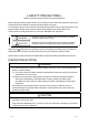
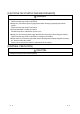
[INSTALLATION PRECAUTIONS] ! CAUTION • Use the PLC in an environment that meets the general specifications contained in the CPU User's Manual to use. Using this PLC in an environment outside the range of the general specifications may cause electric shock, fire, malfunction, and damage to or deterioration of the product.
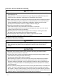
[CAUTIONS ON STARTUP AND MAINTENANCE] ! DANGER • Always turn off all external power supply phases before touching any terminals. Failure to do this may result in malfunction. • Always turn of all external power supply phases before cleaning or tightening the terminal screws. Failure to do this may result in malfunction. • Do not disassemble or modify any module. This will cause failure, malfunction, injuries, or fire.
REVISIONS The manual number is given on the bottom left of the back cover. Print Date Dec., 2000 Jun., 2001 Manual Number SH (NA)-080143-A First Printing SH (NA)-080143-B Addition Section 2.3, 2.4 Revision Delete Section 2.2.1, 2.2.2 Correction SAFETY PRECAUTIONS, About the Generic Terms and Abbreviations, Product Configuration, Section 2.2, 2.4, Section 6.2, 6.2.1, 6.2.2, 6.3.3, 6.5 Feb., 2002 SH (NA)-080143-C Correction About the Generic Terms and Abbreviations, Section 2.2, Section 6.2.1, 6.2.
INTRODUCTION Thank you for purchasing the MELSEC-Q series PLC. Before using the equipment. please read this manual carefully to develop full familiarity with the functions and performance of the Q series PLC you have purchased, so as to ensure correct use. CONTENTS SAFETY PRECAUTIONS..............................................................................................................................AREVISIONS ...........................................................................................
4 SETUP AND PROCEDURES BEFORE OPERATION 4- 1 to 4- 14 4.1 Setup and Procedures before Operation ................................................................................................ 4- 1 4.1.1 When using the master function ....................................................................................................... 4- 1 4.1.2 When using the slave function.......................................................................................................... 4- 2 4.1.
7 PROGRAMMING WHEN EXECUTING THE MASTER FUNCTION 7- 1 to 7- 12 7.1 Precautions on Programming .................................................................................................................. 7- 1 7.2 System Configuration............................................................................................................................... 7- 2 7.3 Setting Parameters ....................................................................................................................
Conformation to the EMC Directive and Low Voltage Instruction For details on making Mitsubishi PLC conform to the EMC directive and low voltage instruction when installing it in your product, please see Chapter 3, "EMC Directive and Low Voltage Instruction" of the User's Manual (Hardware) of the PLC CPU to use. The CE logo is printed on the rating plate on the main body of the PLC that conforms to the EMC directive and low voltage instruction.
Product Configuration The following is a list of the components in this product configuration.
1 OVERVIEW MELSEC-Q 1 OVERVIEW 1 This manual explains the specifications and name of each component of the QJ71DN91 DeviceNet master/slave module, which is used in combination with the MELSEC-Q Series PLC CPU. Please see DeviceNet Specification Manual (Release 2.0), Volumes 1 and 2, for the specifications of DeviceNet. DeviceNet is a registered trademark of Open DeviceNet Vendor Association, Inc. POINT Most of the DeviceNet products on the market are assumed to be compatible.
1 OVERVIEW MELSEC-Q (4) When the module functions as a master node of DeviceNet, I/O communication and message communication with a DeviceNet slave node are possible. (5) When the module functions as a master node of DeviceNet, the module can communicate with a maximum of 63 slave nodes. (6) Selection is available from four types of I/O communication methods when this module functions as a master node in DeviceNet. They are polling, bit strobe, change-of-state and cyclic which are defined in DeviceNet.
2 SYSTEM CONFIGURATION MELSEC-Q 2 SYSTEM CONFIGURATION This chapter explains the system configuration of DeviceNet. 2.1 Overall Configuration 2 A total of 64 modules including a master node, slave nodes and a master/slave node can be connected. Each node is connected via a tap from the trunk line or directly to the trunk line.
2 SYSTEM CONFIGURATION MELSEC-Q (1) Network specification The following explains the network specifications of DeviceNet that uses the QJ71DN91. (a) Communication speed The communication speed can be selected from 125kbaud, 250kbaud, or 500kbaud using the mode switch of the QJ71DN91. The maximum cable length varies depending on the communication speed. See Section 3.1, "Performance Specifications" for details.
2 SYSTEM CONFIGURATION MELSEC-Q 2.2 Applicable Systems This section describes the system configuration for the QJ71DN91. (1) Applicable module and the number of modules that can be installed The following are the CPU module in which the QJ71DN91 can be installed and the number of modules that can be installed.
2 SYSTEM CONFIGURATION MELSEC-Q (4) Software packages supported Correspondence between systems which use QJ71DN91s and software packages are as shown below. The GX Developer is necessary when using a QJ71DN91. Software Version GX Developer Q00J/Q00/ Q01CPU Q02/Q02H/ Q06H/Q12H/ Q25HCPU Q12PH/ Q25PHCPU GX Configurator-DN 2 Single PLC system Version 7 or later Multiple PLC system Version 8 or later Single PLC system Version 4 or later Version 1.
2 SYSTEM CONFIGURATION MELSEC-Q (2) How to check the GX Configuration-DN software version The GX Configurator-DN software version can be checked in GX Developer's "Product information" screen. [Startup procedure] GX Developer "Help" Product information Software version (In the case of GX Developer Version 7) 2.4 About Use of the QJ71DN91 with the Q00J/Q00/Q01CPU Here, use of the QJ71DN91 with the Q00J/Q00/Q01CPU is explained.
2 SYSTEM CONFIGURATION MELSEC-Q 2.5 About Additional Function The added function is described below. Function Serial No. Function Outline Addition of Each Node Communication First five digits of Indicates whether an I/O Error Status (addresses 01C0H to 01C3H serial No. are communication error has /448 to 451) 04102 or later occurred or not in each node. Reference Section Section 3.4.1 (10) POINT Refer to Section 2.3 for the way to confirm the serial No. 2.
3 SPECIFICATIONS MELSEC-Q 3 SPECIFICATIONS 3.1 Performance Specifications This section explains the performance specifications for QJ71DN91, I/O signals for PLC CPU and specifications for buffer memory. See the PLC CPU User's Manual to be used for the general specifications for QJ71DN91.
3 SPECIFICATIONS MELSEC-Q 3.2 Functions This section explains the functions of the QJ71DN91. 3.2.1 Master function (I/O communication function) The I/O communication function executes the I/O data communication with each slave node. In the I/O communication function, the connection type can be set according to the specification of the slave node. There are four connection types: polling, bit strobe, change-of-state, and cyclic. The connection type can be set with a parameter.
3 SPECIFICATIONS MELSEC-Q (2) When the sequence program is used The following explains the I/O communication function when the sequence program is used.
3 SPECIFICATIONS MELSEC-Q (3) Overview of each connection type The following explains an overview of each connection type used during the I/O communication. (a) Polling As shown in the following diagram, the communication method by which the communication with each slave node is repeated, as described from 1) to 6), is the polling communication. The connection that uses this communication is the polling connection. 1) The master node transmits the output data.
3 SPECIFICATIONS MELSEC-Q (b) Bit strobe As shown in the following diagram, the communication method by which the communication with each slave node is repeated, as described from 1) to 4), is the bit strobe communication. The connection that uses this communication is the bit strobe connection. 1) Output information of a maximum of one bit is transmitted simultaneously to each slave node. 2) The slave node transmits the input data by setting the transmission of 1) to trigger.
3 SPECIFICATIONS MELSEC-Q (c) Change-of-state As shown in the following diagram, the communication method that executes the communication of [1] and [2] as the I/O data changes is the change-of-state communication, and the connection that uses this communication is the change-of-state connection. No data transmission is performed unless the I/O data is changed. 1) When the output data of the master node changes, the data is sent to the slave node.
3 SPECIFICATIONS MELSEC-Q (d) Cyclic As shown in the following diagram, the communication method that regularly repeats the communication of [1] and [2] is the cyclic communication, and the connection that uses this communication is the cyclic connection. 1) The data of the master node is sent to the slave node. 2) The data of the slave node is sent to the master node. The cycle of the cyclic communication can be specified for each slave node.
3 SPECIFICATIONS MELSEC-Q 3.2.2 Master function (Message communication function) The message communication function is used to get and set the attribute data of a slave node.
3 SPECIFICATIONS MELSEC-Q (2) Setting attributes PLC CPU QJ71DN91 1) 0110H TO 011FH 2) 0130H TO 3) SET Y12 012FH Next processing X02 X05 Message communication completion 3) Class Instance Attribute Message communication data area Attribute 01A7H Message communication request 0120H 5) Message communication command area Slave node (MAC ID) Message communication result area Class 4) Instance Attribute Message communication complete Instance Attribute 6) Attribute Class Instance Attrib
3 SPECIFICATIONS MELSEC-Q (3) Reading the communication error information PLC CPU QJ71DN91 0110H 1) TO Message communication command area 2) Slave information storage area 0120H 5) FROM X02 X05 012FH 0130H 01A7H 3) X02 X05 Message communication completion I/O communication Class 1 Instance 011FH Message communication request SET Y12 FROM Slave node (MAC ID) Attribute Attribute Instance 2) Attribute Attribute Message communication result area Message communication data area Message com
3 SPECIFICATIONS MELSEC-Q 3.2.3 Slave function (I/O communication function) The I/O communication function executes the communication of the I/O data with the master node using the polling method. (1) When GX Configurator-DN is used The following explains the I/O communication function when the GX Configurator-DN is used.
3 SPECIFICATIONS MELSEC-Q (2) When the sequence program is used The following explains the I/O communication function when the sequence program is used.
3 SPECIFICATIONS MELSEC-Q 3.3 I/O Signals for the PLC CPU This section explains the input/output signals for the PLC CPU of the QJ71DN91. 3.3.1 I/O signal list The I/O signal list for the QJ71DN91 is shown in Table 3.2. The I/O numbers (X/Y) and I/O addresses described from this chapter are applicable when the QJ71DN91 is installed in slot 0 of the basic base module. Table 3.
3 SPECIFICATIONS MELSEC-Q 3.3.2 Details of the I/O signals The following describes the ON/OFF timings and conditions of the I/O signals. (1) Watchdog Timer Error: X00 This is turned ON when an error occurs in the QJ71DN91.
3 SPECIFICATIONS MELSEC-Q (b) When the auto start is set 1) The module ready (X0F) is turned ON when the power is turned ON, and the parameter check is executed automatically. 2) If the parameter check is successful, the I/O communication starts and the I/O communicating (X01) is turned ON. If the parameter check fails, the master function for error set signal (X03) is turned ON and the ERR. LED is lit.
3 SPECIFICATIONS MELSEC-Q (3) I/O Communicating : X01, I/O Communication Request: Y11 (when the slave function is used) These signals are used to start the I/O communication of the slave function with the number of I/O points that is set by the "setting area of the number of slave function reception bytes" and the "setting area of the number of slave function transmission bytes" of the buffer memory. Use these signals while the module ready (X0F) is ON.
3 SPECIFICATIONS MELSEC-Q (4) Message Communication Completion: X02, Message Communication Error Signal: X05, Message Communication Request: Y12 These signals are used to execute the message communication. Message communication can be executed when the "master function communication status" area of the buffer memory is "in operation (C0H)" or "stop (40H)". POINT When making message communication, set the master function parameters.
3 SPECIFICATIONS MELSEC-Q (5) Master Function For Error Set Signal: X03, Master Function For Error Reset Request: Y13 These signals are used to indicate an error while executing the master function and to reset the error code. (a) When an error occurs via the master function, the error information is stored in the "error information for the master function" area of the buffer memory and the master function for error set signal (X03) is turned ON.
3 SPECIFICATIONS MELSEC-Q (7) Saving Parameter To Flash ROM: X06, Save Parameter To Flash ROM Completion: X07, Save Parameter To Flash ROM Request: Y17 (when the master function is used) These signals are used to save the "parameters for the master function" of the buffer memory to the flash ROM in the QJ71DN91. Make a request to save parameters to the flash ROM while the I/O communicating (X01) is OFF.
3 SPECIFICATIONS MELSEC-Q POINT (1) Even if the save parameter to flash ROM request (Y17) is turned ON while the I/O communicating (X01) is ON, save parameter to flash ROM completion (X07) is not turned ON. Turn OFF the I/O communication request (Y11), then after confirming that the I/O communicating (X01) is OFF, turn ON the save parameter to flash ROM request (Y17) from the OFF state.
3 SPECIFICATIONS MELSEC-Q When the parameter check fails: I/O Communication Request (Y11) I/O Communicating (X01) Save Parameter To Flash ROM request (Y17) Parameter check Saving Parameter To Flash ROM (X06) Save Parameter To Flash ROM Completion (X07) Master Function For Error Set Signal (X03) Write parameter data TO instruction POINT (1) Even if the save parameter to flash ROM request (Y17) is turned ON while the I/O communicating (X01) is ON, save parameter to flash ROM completion (X07) is not turne
3 SPECIFICATIONS MELSEC-Q (9) Slave Function For Error Set Signal: X08, Slave Function For Error Reset Request: Y18 These signals notify an error occurrence during execution of the slave function and are used to reset the error code. (a) When an error occurs by the slave function, the error information is stored in the "error information for the slave function" area of the buffer memory, and the slave function for error set signal (X08) is turned ON.
3 SPECIFICATIONS MELSEC-Q (12) Auto Configuration Executing: X14, Auto Configuration Completion: X15, Auto Configuration Request: Y15 These signals are used in order to search the slave nodes that are connected to the network and create parameters automatically. Execute the auto configuration request while the I/O communicating (X01) is OFF. (a) Verify that the DeviceNet device power and the network power are turned ON. (b) To execute the auto configuration, turn ON the auto configuration request (Y15).
3 SPECIFICATIONS MELSEC-Q 3.4 Buffer Memory The buffer memory transfers data between the QJ71DN91 and the PLC CPU. The FROM and TO instructions of the PLC CPU are used to read and write the buffer memory data in the QJ71DN91. The contents of the buffer memory are reset to 0 when the power is turned OFF or when the PLC CPU is reset. However, the "parameter" area is initialized using the saved parameters if the parameters have been saved in the flash ROM. 3.4.
3 SPECIFICATIONS MELSEC-Q Table 3.3 Buffer memory list (2/2) Address Usability Item Description Master function Slave function Write from the PLC CPU allowed? Reference section Hexadecimal Decimal 05FCH 1532 Present Link Scan Time Displays the current link scan time (module: ms). — No 3.4.2 (16) 05FDH 1533 Minimum Link Scan Time Displays the minimum link scan time (module: ms). — No 3.4.2 (17) 05FEH 1534 Maximum Link Scan Time Displays the maximum link scan time (module: ms).
3 SPECIFICATIONS MELSEC-Q 3.4.2 Buffer memory details This section explains the details of the buffer memory. (1) Message communication command (addresses 0110H to 011FH/272 to 287) Use the TO instruction to write the message communication command. (a) To get the attribute data of a slave node 1) Use the TO instruction to set the command data in the "message communication command" area. 2) Use the sequence program to turn ON the message communication request (Y12).
3 SPECIFICATIONS MELSEC-Q (c) To read the communication error information of the slave node 1) Use the TO instruction to set the command data in the "message communication command" area. 2) Use the sequence program to turn ON the message communication request (Y12). 3) The message communication completion (X02) is automatically turned ON when the message communication is completed. 4) Gotten attribute data is stored in the "message communication data" area.
3 SPECIFICATIONS MELSEC-Q (2) Message communication result (addresses 0120H to 012FH/288 to 303) Once the processing by the "message communication command" is executed, the QJ71DN91 sets the processing result in the "message communication result" area and turns ON the message communication completion (X02). The processing result is retrieved by the FROM instruction of the sequence program. The processing result is stored as shown in the following table.
3 SPECIFICATIONS MELSEC-Q Table 3.
3 SPECIFICATIONS MELSEC-Q (c) Reading communication error information The communication error information that was read is stored. The data set in each address is shown in Table 3.14. Table 3.14 Setting data for reading communication error information Buffer memory address (hexadecimal) Item 0130H Slave status 0131H Use prohibited Description Indicates whether or not the slave node is set in the parameters, and the slave node has responded, etc. (See 1).
3 SPECIFICATIONS MELSEC-Q 2) The DeviceNet general error code list is shown in Table 3.15. Table 3.15 DeviceNet general error code list Error code Hexadecimal Decimal 0000H to 0001H 0 to 1 0002H 2 0003H to 0007H 3 to 7 0008H 8 Error name Description Reserved Reserved by DeviceNet Resource unavailable Requested service could not be executed because there was no space in the required resource. Reserved Reserved by DeviceNet Service not supported Requested service is not supported.
3 SPECIFICATIONS MELSEC-Q (4) Master Function Communication Status (address 01B0H/432) The higher and lower bytes indicate the following master communication status: (a) Higher byte This byte indicates the I/O communication status of the QJ71DN91 master function. The values in Table 3.16 are stored according to the communication status. Table 3.
3 SPECIFICATIONS MELSEC-Q (5) Master Function For Error Information (address 01B1H/433) The communication error code that was detected is stored. (a) When an error occurs, the error information is stored in the "master function for error information" area, and the master function for error set signal (X03) is turned ON. (b) The data in the " master function for error information " area is cleared by turning ON the master function for error reset request (Y13) by the sequence program.
3 SPECIFICATIONS MELSEC-Q [Bit ON timing] (a) When I/O communication is started 1) If automatic start has not been set When I/O Communication Request (Y11) is turned ON, parameter check is made. When the parameter check succeeds, the corresponding bit of "Each Node Configuration Status" turns ON, and I/O Communicating (X01) then turns ON. 2) If automatic start has been set When power is switched ON, parameter check is made automatically.
3 SPECIFICATIONS MELSEC-Q (10) Each Node Communication Error Status (addresses 1C0H to 1C3H/448 to 451) These addresses store whether an I/O communication error has occurred or not for each slave node set to the "parameters for the master function" when I/O Communicating (X01) is ON. Note that the error is not detected for the node where "Down Node Detection Disable Status (addresses 01CCH to 01CFH/460 to 463)" has been set. • When the corresponding bit is ON : Communication error exists.
3 SPECIFICATIONS MELSEC-Q (12) Down Node Detection Disable Status (addresses 01CCH to 01CFH/460 to 463) These addresses set whether or not the I/O signal, "slave down signal" (X04), reflects the down status of each slave node as indicated by the "each node communication status" (addresses 01BCH to 01BFH/444 to 447). • When the corresponding bit is ON: The slave down signal (X04) is not turned ON even if the corresponding slave node is down.
3 SPECIFICATIONS MELSEC-Q Table 3.22 Parameter setting data (1/2) Buffer memory address (hexadecimal) Item Description 01D4H to 01D6H Use prohibited 01D7H Constant scan Specifies to make the link scan time constant.
3 SPECIFICATIONS MELSEC-Q Table 3.
3 SPECIFICATIONS MELSEC-Q POINT (1) Write "0" in the unnecessary parameter area when creating a parameter. Otherwise, an error may occur if the previous data remains. (2) Because of the limited number of writes of the flash ROM, execute the save parameter to flash ROM request (Y17) only when creating a new parameter or changing a parameter. Table 3.23 Details of the expected packet rate and production inhibit time Expected packet rate (1) Sets the communication watchdog timer value for the slave node.
3 SPECIFICATIONS MELSEC-Q (14) Auto configuration operation setting (address 03F0h/1008) The auto configuration type and the maximum detection node numbers are set as follows: 1) Higher byte Sets the auto configuration type. 00H: All configuration 01H: Additional configuration (Default value: 00H) 2) Lower byte Sets the maximum detection node number.
3 SPECIFICATIONS MELSEC-Q (15) Master Function For IO Address Area (addresses 0500H to 05FBH/1280 to 1531) The head addresses and sizes (in word module) of the "input data for the master function" area and the "output data for the master function" area, which are used by each slave node, are stored. This area can be used to check the head address of each node.
3 SPECIFICATIONS MELSEC-Q (19) Slave Function Communication Status (address 0600H/1536) These addresses indicate the I/O communication status of the QJ71DN91 slave function. The values listed in Table 3.24 are stored according to the status of communication. Table 3.
3 SPECIFICATIONS MELSEC-Q (20) Slave Function For Error Information (address 0601H/1537) The communication error code when the slave function is used is stored. (a) When an error occurs, the error information is stored in the "slave function for error information" area and the slave function for error set signal (X08) is turned ON. (b) The data of the " slave function for error information " area is cleared by turning ON the slave function for error reset request (Y18) by the sequence program.
3 SPECIFICATIONS MELSEC-Q (22) Model Name Display (addresses 0620H to 0624H /1568 to 1572) "QJ71DN91" is stored in ASCII code. 0620H "J" "Q" 0621H "1" "7" 0622H "N" "D" 0623H "1" "9" 0624H "0" "0" (23) Node Number (address 0625H/1573) The node number currently in operation is stored. 00H to 3FH (Stores in binary code.) (24) Mode Switch Number (address 0626H/1574) The mode switch number currently in operation is stored.
3 SPECIFICATIONS MELSEC-Q (25) H/W Test Item Display Area (address 062EH/1582) The test item numbers currently in operation during the hardware test and communication test are stored. Table 3.
3 SPECIFICATIONS MELSEC-Q Table 3.29 Contents of communication test result Error code Contents Node number duplicate error 0001H Detailed contents Handling method There is another node in the network which has the same node number as the local node. • Assign different node numbers to all nodes in the network. 0002H Bus off error A bus off occurred during the test. • Set the communication speed of all nodes in the network to the same value.
3 SPECIFICATIONS MELSEC-Q (29) Master Function Receive Data (addresses 0700H to 07FFH/1792 to 2047) The data that was received from each slave node is stored. The data assignment is shown below. The data is stored in the word boundaries of the slave nodes. Double-word data is stored in the order of lower word first and higher word next. If there is an odd number of byte input modules, one byte of empty area will be inserted for alignment at the word boundary.
3 SPECIFICATIONS MELSEC-Q (30) Master Function Transmit Data (addresses 0900H to 09FFH /2304 to 2559) The data to be transmitted to each slave node is written by the TO instruction. The data assignment is shown below. The data is stored in the word boundaries of the slave nodes. Double-word data is stored in the order of lower word first and higher word next. If there is an odd number of byte input modules, one byte of empty area will be inserted for alignment at the word boundary.
3 SPECIFICATIONS MELSEC-Q (31) Slave Function Receive Data (addresses 0B00H to 0B3FH/2816 to 2879) The data received from the master node is stored. The data of the size that is set by the "setting area of the number of slave function reception bytes" becomes valid. 0B00H 2nd byte 1st byte 0B01H 4th byte 3rd byte 0B02H 6th byte 5th byte (32) Slave Function Transmit Data (addresses 0C00H to 0B3FH/3072 to 3135) The data to be transmitted to the master node is written by the TO instruction.
3 SPECIFICATIONS MELSEC-Q 3.5 Communication Performance 3.5.1 Scan time The scan time represents the time to wait for responses from all nodes after the QJ71DN91 starts sending requests in the polling or bit strobe communication. The scan time can be calculated using the following expression: Scan time LS = Σ (TIn + TOn + 0.097) + 0.222 BR + 0.1 (module: ms) TIn: Transmission time of the reception data from the nth slave. (See the following expression for details.
3 SPECIFICATIONS MELSEC-Q 3.5.2 Communication cycle The communication cycle is the time interval between the moment a polling or a bit strobe request is sent to a slave node and the moment another request is sent to the same node. A different communication cycle can be set for each node by setting the production inhibit time parameter. The communication cycle for each slave node can be calculated using the following expression: Communication cycle LC = LS + production inhibit time (module: ms) 3.5.
4 SETUP AND PROCEDURES BEFORE OPERATION MELSEC-Q 4 SETUP AND PROCEDURES BEFORE OPERATION This chapter describes the procedures up to system startup using the QJ71DN91. 4.1 Setup and Procedures before Operation 4.1.1 When using the master function Start Perform a hardware test (mode 9). Set to mode 0 to 2. Use GX Configurator-DN? Yes Create "parameters for the master function" using GX Configurator-DN. Set "auto communication start settings" using GX Configurator-DN and load it to the QJ71DN91.
4 SETUP AND PROCEDURES BEFORE OPERATION MELSEC-Q 4.1.2 When using the slave function Start Perform a hardware test (mode 9). Set to mode 3 to 5. Use GX Configurator-DN? Yes 4 No Change the number of I/O points of the slave? Create "parameters for the slave function" using GX Configurator-DN. No Creating the parameters for the slave function Yes Create a sequence program to change the number of I/O points of the slave.
4 SETUP AND PROCEDURES BEFORE OPERATION MELSEC-Q 4.1.3 When using both the master function and slave function Start Perform a hardware test (mode 9). Set to mode 0 to 2. Use GX Configurator-DN? Yes Create "parameters for the master function" using GX Configurator-DN. Create "parameters for the slave function" using GX Configurator-DN. No Create "parameters for the master function" using a sequence program. Create "parameters for the master function" using auto configuration.
4 SETUP AND PROCEDURES BEFORE OPERATION MELSEC-Q 4.2 Loading and Installation The following section explains the precautions when handling the QJ71DN91 from the time they are unpacked until they are installed. For more details on the loading and installation of the module, refer to the User's Manual for the PLC CPU used. 4.2.1 Handling precautions (1) Do not drop the module casing or connector, or do not subject it to strong impact.
4 SETUP AND PROCEDURES BEFORE OPERATION MELSEC-Q 4.3 Component Names and Settings The following section describes the component names of the QJ71DN91, the meanings of the LED displays, and the setting procedure of the switches. QJ71DN91 RUN MS NS ERR.
4 SETUP AND PROCEDURES BEFORE OPERATION MELSEC-Q 4.3.1 Meanings of the LED displays The following explains the names and meanings of the LEDs located on the top surface of the QJ71DN91 when the mode is set to 0 to 8. For the meanings of the LEDs when the mode is set to 9 to C, see Section 4.4, "Hardware Test" or Section 4.6, "Communication Test". Table 4.1 LED names and meanings of LED displays QJ71DN91 RUN LED name MS Color RUN Green ERR. Red Off: Watchdog timer error NS ERR.
4 SETUP AND PROCEDURES BEFORE OPERATION MELSEC-Q 4.3.2 Node number setting switch The following explains the node number setting switch of the QJ71DN91. Table 4.2 Description of the node number setting switch Name Description 7 2 3 5 X10 Node number setting switch Sets the node number of the module. (Setting at the time of shipment from the factory: 0) Since the node number is recognized when the module is powered on or reset, do not change the node number during module operation.
4 SETUP AND PROCEDURES BEFORE OPERATION MELSEC-Q 4.4 Hardware Test The hardware test checks whether or not the standalone module operates normally. It performs a ROM check, RAM check, self-loop test, etc. Be sure to perform the hardware test before configuring a system. For more details on the test related to DeviceNet communication, perform a test by referring to Section 4.6, "Communication Test" after wiring is complete.
4 SETUP AND PROCEDURES BEFORE OPERATION MELSEC-Q 4.5 Connecting the Communication Cables to the QJ71DN91 (1) Connecting the communication cables The following explains the connection method of the communication cables to the QJ71DN91. V+ (red) CAN_H (white) Shield (drain wire) CAN_L (blue) V- (black) The figure above shows the QJ71DN91's DeviceNet connectors. A sticker in the corresponding cable color is pasted on each connector.
4 SETUP AND PROCEDURES BEFORE OPERATION MELSEC-Q 4.6 Communication Test The transmission test and reception test are performed by connecting the QJ71DN91 and other DeviceNet devices with a communication cable. There is no restriction on the node number setting of the communication counterpart. Execute the test in the following sequence: Start Connect the QJ71DN91 and the DeviceNet station of the communication counterpart with a DeviceNet cable.
4 SETUP AND PROCEDURES BEFORE OPERATION MELSEC-Q 4.7 Instructions for Connecting the Network Power Supply This section explains the instructions for connecting the network power supply. 4.7.1 Network power supply unit installation position Follow the procedure below to determine the position to install the network power supply unit. 1) Calculate the current consumption of the nodes required on the network. 2) Measure the total length of the network. 3) Refer to Tables 4.4 and 4.
4 SETUP AND PROCEDURES BEFORE OPERATION MELSEC-Q 4.7.2 Calculating network power supply unit installation position and current capacity This section explains the calculating network power supply unit installation position and current capacity. (1) Network power supply unit connected to an end of the network The current capacity is calculated as shown below when the network power supply unit is connected to the end of a thick-cable network with a total length of 200 m.
4 SETUP AND PROCEDURES BEFORE OPERATION (3) MELSEC-Q Remedy for insufficient network power supply current capacity If the network power supply unit is connected to a thick-cable network, as shown below. Network power supply unit Termination resistance Termination resistance Master station Slave station Slave station Slave station Slave station Slave station 1.1A 1.25A 0.5A 0.25A 0.25A 0.
4 SETUP AND PROCEDURES BEFORE OPERATION (4) MELSEC-Q Mixed trunk line and drop line The current capacity is calculated as shown below when the network power supply unit is connected to a network with 200 m of thick-cable trunk line and 6 m of thin-cable drop line. Network power supply unit Termination resistance Termination resistance Master station Slave station Slave station Slave station 1.0A 0.15A 0.05A 0.25A Slave station 0.
5 PARAMETER SETTINGS MELSEC-Q 5 PARAMETER SETTINGS This chapter explains the setting items of the parameters that are required to run the QJ71DN91. The following three methods are available to set the parameters. The parameters set are saved in the flash ROM inside the QJ71DN91 as needed. Once the parameters are saved in the flash ROM, it is not necessary to save them in the flash ROM until they are changed. The parameters can be written to the flash ROM for a maximum of 100,000 times.
5 PARAMETER SETTINGS MELSEC-Q 5.1.2 Parameters for the slave function The following explains the setting items of the parameters for the slave function.
5 PARAMETER SETTINGS MELSEC-Q 5.3 Setting Using the Auto Configuration Function The Auto Configuration function automatically creates parameters by detecting a slave node in a DeviceNet network, which is a supplementary function for creating parameters. The Auto Configuration function can reduce the load on the sequence program for parameter settings. When the Auto Configuration function is executed, it takes up to 60 seconds until it completes.
5 PARAMETER SETTINGS (2) MELSEC-Q Description of auto configuration settings Table 5.1 lists the items that are automatically detected and set with the Auto Configuration function. To change the contents of settings, use the sequence program. Table 5.
5 PARAMETER SETTINGS MELSEC-Q Table 5.
5 PARAMETER SETTINGS MELSEC-Q Table 5.
6 UTILITY PACKAGE (GX Configurator-DN) MELSEC-Q 6 UTILITY PACKAGE (GX Configurator-DN) 6.1 Functions of the Utility Package Table 6.1 lists the functions of the utility package (GX Configurator-DN). Table 6.1 Utility package (GX Configurator-DN) function list Function Description (1) Auto refresh (2) Monitor/test Flash ROM setting 6-1 Sets the QJ71DN91's buffer memory that refreshes automatically.
6 UTILITY PACKAGE (GX Configurator-DN) MELSEC-Q 6.2 Installing and Uninstalling the Utility Package See "Method of installing the MELSOFT Series" attached with the utility package regarding the install and uninstall operation for the utility package. 6.2.1 User precautions The following explains the precautions on using the GX Configurator-DN.
6 UTILITY PACKAGE (GX Configurator-DN) MELSEC-Q (6) About the number of parameters that can be set in GX Configurator-DN The number of parameters that can be set by the GX Configurator for an intelligent function module installed in the CPU module and in a remote I/O station of the MELSECNET/H network system is limited.
6 UTILITY PACKAGE (GX Configurator-DN) MELSEC-Q 6.2.2 Operating environment The operating environment of the personal computer where the GX Configurator-DN is used is explained. Item Peripheral devices Installation (Add-in) destination 1 ® Computer main unit Hard disk 2 Add-in to GX Developer Version 4 (English version) or later Personal computer on which Windows operates. CPU Refer to the following table "Used operating system and performance required for Required memory personal computer".
6 UTILITY PACKAGE (GX Configurator-DN) MELSEC-Q 6.3 Explanation of Utility Package Operation 6.3.1 How to perform common utility package operations (1) Available control keys Special keys that can be used during operation of the utility package and their applications are shown in the table below. Name of key Esc Application Cancels a newly entered value when entering data in a cell. Close the window. Tab Ctrl Moves between controls in the window.
6 UTILITY PACKAGE (GX Configurator-DN) (2) MELSEC-Q Data to be created with the utility package The data and files shown below that are created with the utility package are also processed using GX Developer operation. Figure 6.1 shows which operation processes which data or file. (a) This data is created with the automatic refresh setting, and stored in the intelligent function module parameter file of the project to be created using GX Developer.
6 UTILITY PACKAGE (GX Configurator-DN) MELSEC-Q (a) The data set with flash ROM settings is called the flash ROM data, which can be saved in a desired directory different from the GX Developer project. (b) Steps 4) and 5) shown in Figure 6.1 are performed as follows: 4) This step can be executed from the Flash ROM Setting screen or Monitor/Test screen.
6 UTILITY PACKAGE (GX Configurator-DN) MELSEC-Q 6.3.2 Overview of operation GX Developer screen [Tools] - [Intelligent function utility] - [Start] Screen for intelligent function module parameter setting module select Enter "Start I/O No.," then select "Package name" and "Module model name." See Section 6.3.3. 1) Auto refresh Auto refresh settings screen See Section 6.4.
6 UTILITY PACKAGE (GX Configurator-DN) MELSEC-Q 1) [Tools] - [Flash ROM setting] [Online] - [Monitor/test] Select monitor/test module Flash ROM settings screen Select Monitor/test Select "Package name" and "Module model name." Enter "Start I/O No.," then select "Package name" and "Module model name." Monitor/Test screen Flash ROM settings screen See Section 6.6. See Section 6.5.
6 UTILITY PACKAGE (GX Configurator-DN) MELSEC-Q 6.3.3 Starting the intelligent function module utility [Purpose of Setting] By starting the intelligent function module utility from the GX Developer, display the Parameter Setting Module Selection screen. From this screen, the screens used to perform auto refresh and monitor/test module selection (selecting the module for which monitoring/testing is to be performed) of the QJ71DN91 can be started.
6 UTILITY PACKAGE (GX Configurator-DN) (3) MELSEC-Q Menu bar (a) File items With file operation, the parameters of the intelligent function module for the project opened with the GX Developer can be manipulated. [Open file] : Reads the parameter file. [Close file] : Closes the parameter file. If the data in the file was modified, a dialog box asking whether or not to save the file will appear. [Save file] : Saves the parameter file. [Delete file] : Deletes the parameter file.
6 UTILITY PACKAGE (GX Configurator-DN) MELSEC-Q 6.4 Auto Refresh Settings [Purpose of Setting] Sets the QJ71DN91's buffer memory that is automatically refreshed. For the auto refresh setting items, see Section 6.1. Reading and writing with the sequence program will no longer be required by setting auto refresh. [Startup procedure] "Start I/O No. " "Package name" "Module model name" Auto refresh Enter the start I/O No. in hexadecimal.
6 UTILITY PACKAGE (GX Configurator-DN) MELSEC-Q [Explanation of items] (1) Description of the screen display Buffer size on module side : Displays the buffer memory size of the setting item. Number of transfer words on module side : Displays the number of words to be transferred. Transfer direction : " " indicates that data is written from the PLC CPU to the buffer memory.
6 UTILITY PACKAGE (GX Configurator-DN) MELSEC-Q 6.5 Monitor/Test [Purpose of Setting] Buffer memory monitoring/testing and I/O signal monitoring/testing are started from this screen. [Startup procedure] Select monitor/test module screen model name" "Start I/O No. " "Package name" "Module Monitor/test Enter the start I/O No. in hexadecimal. The screen can also be started from the GX Developer Version 6 or later system monitor. See GX Developer Operating Manual for details.
6 UTILITY PACKAGE (GX Configurator-DN) MELSEC-Q Each Node Configuration Status Monitor Each Node Communication Error Status Monitor Each Node Communication Status Monitor Each Node Obstacle Status Monitor 2) 1) 6 - 15 6 - 15
6 UTILITY PACKAGE (GX Configurator-DN) Down Node Detection Disable Status MELSEC-Q Master Function For IO Address Area Monitor 2) 3) Message Communication Area Monitor/Test 6 - 16 Master Function Receive Data Monitor 6 - 16
6 UTILITY PACKAGE (GX Configurator-DN) Master Function Transmit Data Monitor/Test MELSEC-Q Slave Function Transmit Data Monitor/Test 3) 4) Slave Function Receive Data Monitor 6 - 17 Auto Configuration 6 - 17
6 UTILITY PACKAGE (GX Configurator-DN) MELSEC-Q Flash ROM Clear 4) Parameter Backup Parameters saved in a file can be edited with "Flash ROM setting".
6 UTILITY PACKAGE (GX Configurator-DN) MELSEC-Q [Explanation of items] (1) Description of screen display Setting item Current value : Displays the I/O signal and buffer memory names. : Monitors the I/O signal status and present buffer memory value. Setting (value) : Enter or select the value to be written into the buffer memory with test operation. (2) Explanation of the command buttons Write to module Writes the parameters into the flash ROM of the QJ71DN91.
6 UTILITY PACKAGE (GX Configurator-DN) MELSEC-Q 6.6 Flash ROM Settings [Purpose of Setting] The contents of flash ROM settings are edited offline. The edited parameters can be written into the module on the "Parameter Backup" screen of "Monitor/Test".
6 UTILITY PACKAGE (GX Configurator-DN) MELSEC-Q [Explanation of items] (1) Description of screen display Setting item : Displays the parameter names. Setting (value) : Enter or select the value to be set in the flash ROM. (2) 6 - 21 Explanation of the command buttons File save Saves the parameters in the hard disk, etc. File read Reads the parameters saved in the hard disk, etc. Close Closes the screen that is currently open and returns to the previous screen.
7 PROGRAMMING WHEN EXECUTING THE MASTER FUNCTION MELSEC-Q 7 PROGRAMMING WHEN EXECUTING THE MASTER FUNCTION This chapter explains programming when the master function is executed. 7.1 Precautions on Programming This section explains the precautions when creating a program. (1) Observe the following to perform input/output communication with a slave node. • Place the I/O communication read processing program at the beginning of a sequence program.
7 PROGRAMMING WHEN EXECUTING THE MASTER FUNCTION MELSEC-Q 7.2 System Configuration The programs explains in this chapter are based on the following system configuration: 1) The QJ71DN91 (master node) is set to node number 0, the first remote I/O is set to node number 1, the second remote I/O is set to node number 2, the third QJ71DN91 (slave node) is set to node number 4, and the fourth remote I/O is set to node number 3.
7 PROGRAMMING WHEN EXECUTING THE MASTER FUNCTION MELSEC-Q The following shows the relationships among the PLC CPU, master node buffer memory and each slave node. PLC CPU QJ71DN91 master node Reception data X100 to X107 FROM 700H X110 to X14F 702H Input 00 to input 07 Node No. 4 reception 703H FROM 705H 706H QJ71DN91 slave node (node No. 4) 8-byte transmission/reception C00H 704H X160 to X16F I00 to I07 Node No. 1 reception 701H FROM Remote I/O (Node No. 1) 8-point input Node No.
7 PROGRAMMING WHEN EXECUTING THE MASTER FUNCTION MELSEC-Q 7.3 Setting Parameters This section explains examples of program for setting parameters. If GX Configurator-DN is used, the programs described in Section 7.3.1 through Section 7.3.3 will not be required. 7.3.1 Parameter settings using the sequence program The following shows a method for setting parameters using the sequence program.
7 PROGRAMMING WHEN EXECUTING THE MASTER FUNCTION Command for setting the parameters for the master function MELSEC-Q Sets the node number of the third slave node to 4 and the message group to 3. Sets the connection type of the third slave node to polling.
7 PROGRAMMING WHEN EXECUTING THE MASTER FUNCTION MELSEC-Q 7.3.2 Creating parameters using auto configuration The following explains a method for creating parameters using auto configuration. Auto configuration command All configuration Maximum detection station number = 4 Auto configuration command Auto configuration request Checks auto configuration in progress. Checks the completion of auto configuration. Resets the auto configuration request. Auto configuration command 7.3.
7 PROGRAMMING WHEN EXECUTING THE MASTER FUNCTION MELSEC-Q 7.4 I/O Communication with Slave Nodes This section explains an example of a sequence program that performs I/O communication. If GX Configurator-DN is used, the FROM and TO instructions are not required. Parameter setting program Parameter setting program (See Section 7.3.) I/O communication start command Sets the initial setting value of transmission data. I/O communication start request Reads each node's communication status data. Node No.
7 PROGRAMMING WHEN EXECUTING THE MASTER FUNCTION MELSEC-Q 7.5 Performing Message Communication This section explains an example of a sequence program that performs message communication. 7.5.1 Example of message communication read The following shows an example of a sequence program that reads attributes from node number 3. In sections enclosed with a dashed line, the area that is actually read and written as well as the class ID, instance ID and attribute ID are different depending on the slave node.
7 PROGRAMMING WHEN EXECUTING THE MASTER FUNCTION MELSEC-Q 7.5.2 Example of message communication write The following shows an example of a sequence program that writes attributes to node number 3. In sections enclosed with a dashed line, the area that is actually read and written as well as the class ID, instance ID and attribute ID are different depending on the slave node. Therefore, refer to the applicable manual of the slave node. Attribute write command Sets write data in D30.
7 PROGRAMMING WHEN EXECUTING THE MASTER FUNCTION MELSEC-Q 7.6 Obtaining Error Information This section explains an example of a sequence program that obtains the error information for the master function. Reads the error code from the buffer memory. Number of station in which an error has occurred Error information Error code Error reset Sets the error reset request. Resets the error reset request.
7 PROGRAMMING WHEN EXECUTING THE MASTER FUNCTION MELSEC-Q 7.7 Allocating Transmission/Reception Data Storage Devices for Future Expansion If the transmission/reception data of each slave node varies depending on the system, it is necessary to change the sequence program when the transmission/reception data length changes.
7 PROGRAMMING WHEN EXECUTING THE MASTER FUNCTION MELSEC-Q The following explains an example of the sequence program used in this case. Parameter setting program Parameter setting program (See Section 7.3.) I/O communication start command Starts I/O communication. Reads the I/O address area information. Reads the reception data according to the I/O address area information. Controls based on the reception data that has been read.
8 PROGRAMMING WHEN EXECUTING THE SLAVE FUNCTION MELSEC-Q 8 PROGRAMMING WHEN EXECUTING THE SLAVE FUNCTION This chapter explains programming when the slave function is executed. 8.1 System Configuration The programs explained in this chapter are based on the following system configuration: 1) The reception data is allocated from X200 to X27F, and the transmission data is allocated from Y200 to Y27F. 2) If an error occurs, the error information is read to D500.
8 PROGRAMMING WHEN EXECUTING THE SLAVE FUNCTION MELSEC-Q 8.2 Setting Parameters Using the Sequence Program This section explains an example of a sequence program for setting parameters. Command for setting parameters for the slave function Sets the number of reception bytes to 16 bytes. Sets the number of transmission bytes to 16 bytes. Writes the parameter data into the buffer memory.
8 PROGRAMMING WHEN EXECUTING THE SLAVE FUNCTION MELSEC-Q 8.3 I/O Communication with the Master Node This section explains an example of a sequence program that performs I/O communication with the master node. Parameter setting program Parameter setting program (See Section 8.2.) I/O communication start command Sets the initial setting value of transmission data. I/O communication start request Reads reception data. Input data processing program Output data processing program Writes transmission data.
8 PROGRAMMING WHEN EXECUTING THE SLAVE FUNCTION MELSEC-Q 8.4 Obtaining Error Information This section explains an example of a sequence program that obtains the error information for the slave function. Reads the error code from the buffer memory. Error handling program Error reset Sets the error reset request. Resets the error reset request.
9 TROUBLESHOOTING MELSEC-Q 9 TROUBLESHOOTING This chapter explains the contents of errors that may occur while using the QJ71DN91 as well as their troubleshooting procedures. This chapter consists of the following two sections: Section 9.1 Items to Check When an Error Occurs Shows troubleshooting procedures based on the phenomenon of errors. Section 9.2 Error Codes Shows the action to be taken based on the error codes.
9 TROUBLESHOOTING MELSEC-Q 9.1 Items to Check When an Error Occurs This section explains the items to check when an error occurs and its troubleshooting procedure: 9.1.1 Checking the LEDs Occurrence of an error Is the mode switch set between 0 and 8? No Reset by setting the mode switch between 0 and 8. No (The NS LED is off.) Turn ON the module power. No Turn ON the network power (24V).
9 TROUBLESHOOTING MELSEC-Q 9.1.2 When communication with all slave nodes cannot be performed (using the master function) Communication with all slave nodes cannot be performed (the NS LED is flashing in green or lit in red) Is the mode switch set between 0 and 2 or between 6 and 8? No Reset by setting the mode switch between 0 and 2 or between 6 and 8. No Connect the communication cable securely. No Turn ON the network power. No Set the same communication speed in all stations.
9 TROUBLESHOOTING MELSEC-Q 9.1.3 When communication with a specific slave node cannot be performed (using the master function) Communication with a specific slave node cannot be performed (when the NS LED is flashing in red) Is the slave node power turned ON? No Turn ON the slave node power. Yes Is the communication cable securely connected to the slave node? No Connect the communication cable securely. No Set the same communication speed as that of other nodes.
9 TROUBLESHOOTING MELSEC-Q 9.1.4 When communication with the master node cannot be performed (using the slave function) Communication with the master node cannot be performed (when the NS LED is flashing in green or lit in red) Is the mode switch set between 3 and 8? No Reset by setting the mode switch between 3 and 8. No Connect the communication cable securely. No Turn ON the network power.
9 TROUBLESHOOTING MELSEC-Q 9.2 Error Codes This section explains the contents of error codes and actions to be taken. Error codes are classified into the communication error codes and the execution error codes during message communication. (1) As for the communication error codes, read them when either the master function for error set signal (X03) or the slave function for error set signal (X08) is turned ON, and check the contents of the errors.
9 TROUBLESHOOTING MELSEC-Q Detection time period Error code (HEX.) Error detection 07H QJ71DN91 No slave node has been set. • Set at least one slave node. 08H QJ71DN91 The total input data length of all slave nodes is too long. • Reduce the total input data length of all slave nodes to 512 bytes or less. 09H QJ71DN91 The total output data length of all slave nodes is too long. • Reduce the total output data length of all slave nodes to 512 bytes or less.
9 TROUBLESHOOTING MELSEC-Q (3) when the error-detected node number (lower byte of error information) is other than FFH and FEH Detection time period Error code (HEX.) Error detection 01H QJ71DN91 A network problem was detected after communication was started. 1EH QJ71DN91 Slave node did not respond. 20H Slave node Slave node responded with a non-prescribed error. 23H Slave node Slave node responded with an error when establishing a connection.
9 TROUBLESHOOTING MELSEC-Q 9.2.2 Execution error codes of message communication (using the master function only) The execution error codes are stored in buffer memory address 0121H. At normal end: 0 When abnormal: Execution error code Buffer memory 0121H At normal completion: 0 When abnormal: Execution error code (1) When reading the communication error information Error code (Dec.) Error detection 161 QJ71DN91 Description The specified slave node number is other than 0 to 63.
9 TROUBLESHOOTING Error code (Dec.) 19 Error detection Slave node MELSEC-Q Description Corrective action Sufficient data to execute the specified operation was not provided. • Check that the specified MAC ID, class ID, instance ID and attribute ID are correct. • In case of attribute write, verify that the specified data is sufficient and the data length is correct.
9 TROUBLESHOOTING MELSEC-Q 9.3 Verifying the QJ71DN91 Status on the GX Developer System Monitor When the QJ71DN91 detailed information is selected on the GX Developer system monitor, the error codes and LED illumination status can be verified. (a) Setting procedure Select the module by clicking "Diagnostics" - "System Monitor," and then click "Module's is Detailed Information" - "H/W Information." (b) Product information Displays the function version and serial No.
9 TROUBLESHOOTING MELSEC-Q (c) H/W LED Information Displays the LED illumination status of the QJ71DN91. (0: off, 1: on) ERR: Indicates the "ERR" LED on status. MS RED: Indicates the "MS red" LED on status. MS GREEN: Indicates the "MS green" LED on status. NS RED: Indicates the "NS red" LED on status. NS GREEN: Indicates the "NS green" LED on status. (d) H/W SW Information Displays the switch setting status of the QJ71DN91. NA: Displays the node number setting status.
APPENDIX MELSEC-Q APPENDIX Appendix 1 External Dimension Diagram The following figure shows an external dimension diagram of the QJ71DN91: QJ71DN91 RUN MS NS ERR. NODE ADDRESS 7 8 2 3 4 5 6 9 X10 0 1 2 3 7 8 23 F0 1 4 56 9 0 1 78 9 CD AB E 98 4 5 6 X1 MODE/DR 0 : M/125 1 : M/250 2 : M/500 M 3 : S/125 O 4 : S/250 D 5 : S/500 E 6 : D/125 7 : D/250 8 : D/500 QJ71DN91 90 12 27.4 App.
APPENDIX MELSEC-Q Appendix 2 Differences between the QJ71DN91 and the AJ71DN91/A1SJ71DN91 The following table lists the differences between the QJ71DN91 and the AJ71DN91/A1SJ71DN91: Model name QJ71DN91 Function AJ71DN91/A1SJ71DN91 DeviceNet master/slave function DeviceNet master function and DeviceNet slave function DeviceNet master function only Number of I/O points of the DeviceNet master function Input 4096 points, output 4096 points Input 2048 points, output 2048 points Auto configuration fu
APPENDIX MELSEC-Q Appendix 3 Parameter Setting Sheet (For the Master Function) Item Setting range Buffer memory address Constant scan 0 ms to 65535 ms 01D7H Item Setting range Buffer memory address Node number Higher byte: 01H to and message 04H or 80H group of the nth slave node Lower byte: 00h to 3FH (0 to 63) Connection type of the nth slave node 0001H, 0002H, 0004H, 0008H, Higher byte: Output byte module Byte module count count of the Lower byte: nth slave node Input byte module count Highe
APPENDIX MELSEC-Q Appendix 4 Parameter Setting Sheet (For the Slave Function) Setting range Buffer memory address Setting area for the number of slave function input points 0 to 128 bytes 060EH Sets the I/O data reception size for the slave function parameters. Setting area for the number of slave function output points 0 to 128 bytes 060FH Sets the I/O data transmission size for the slave function parameters.
APPENDIX MELSEC-Q Appendix 5 List of Communication Parameters of Slave Nodes Manufactured by Various Manufacturers The following table lists an example of parameter setting values in order to communicate with slave nodes manufactured by various manufacturers. For more details on the parameter settings, please contact each manufacturer.
APPENDIX MELSEC-Q Appendix 6 EDS File of the QJ71DN91 The following shows the EDS file of the QJ71DN91. The EDS file is stored in the CDROM of GX Configurator-DN. $ Mitsubishi Master/Slave EDS file $ File Description Section [File] DescText="QJ71DN91 EDS file"; CreateDate=08-28-2000; CreateTime=12:00:00; ModDate=08-28-2000; ModTime=12:00:00; Revision=1.
APPENDIX MELSEC-Q MEMO App - 7 App - 7
INDEX Ind. [A] Auto configuration completion ...................... 3-23 Auto communication start setting.................. 3-46 Auto configuration executing......................... 3-23 Auto configuration operation setting ............. 3-40 Auto configuration request ............................ 3-23 [B] [F] Function version...............................................2-4 [G] GX Configurator-DN ................................ 2-4, 6-1 GX Developer ..................................................
[M] Ind. Model name display ...................................... 3-44 Module ready................................................. 3-22 [T] Transmission delays ......................................3-50 [W] [N] Watchdog timer error ....................................3-14 Node number................................................. 3-44 [O] Obtaining error information (master function) ........................................... 7-10 Obtaining error information (slave function) ... 8-4 ODVA.......
WARRANTY Please confirm the following product warranty details before starting use. 1. Gratis Warranty Term and Gratis Warranty Range If any faults or defects (hereinafter "Failure") found to be the responsibility of Mitsubishi occurs during use of the product within the gratis warranty term, the product shall be repaired at no cost via the dealer or Mitsubishi Service Company.
Microsoft, Windows, Windows NT are registered trademarks of Microsoft Corporation in the United States and other countries. Pentium is a registered trademark of Intel Corporation in the United States and other countries. Other company and product names herein are either trademarks or registered trademarks of their respective owners. SPREAD Copyright (c) 1996 FarPoint Technologies, Inc.
MITSUBISHI ELECTRIC HEADQUARTERS EUROPEAN REPRESENTATIVES EUROPEAN REPRESENTATIVES EUROPEAN REPRESENTATIVES MITSUBISHI ELECTRIC EUROPE EUROPE B.V. German Branch Gothaer Straße 8 D-40880 Ratingen Phone: +49 (0)2102 486-0 Fax: +49 (0)2102 486-1120 e mail: megfamail@meg.mee.com MITSUBISHI ELECTRIC FRANCE EUROPE B.V. French Branch 25, Boulevard des Bouvets F-92741 Nanterre Cedex Phone: +33 1 55 68 55 68 Fax: +33 1 55 68 56 85 e mail: factory.automation@fra.mee.com MITSUBISHI ELECTRIC IRELAND EUROPE B.V.