AUTO-SCANNING WITH DIGITAL CONTROL COLOR DISPLAY MONITOR MODEL NSB1107STTUW USER’S GUIDE For future reference, record the serial number of your display monitor in the space below: SERIAL No. The serial number is located on the rear cover of the monitor. Internet Home Page: http://www.mitsubishi-display.com/ ® Supplying Windows 95/98 INF File download service, new product information, etc.
-2-
CONTENTS 1.1 Features ........................................................ 6 CAUTION 1.2 Internal Preset Memory Capability ................ 7 The power cord provided with this monitor is designed for safety and must be used with a properly grounded outlet to avoid possible electrical shock. 1.3 Power Management Function ....................... 7 Do not remove the monitor cabinet as this can expose you to very high voltages and other hazards. 1.6 Cleaning Your Monitor ..............................
As an ENERGY STAR Partner, Mitsubishi Electric Corporation has determined that this product meets the ENERGY STAR guidelines for energy efficiency. RADIO INTERFERENCE REGULATIONS STATEMENT FOR U.S.A. This equipment has been tested and found to comply with the limits for a Class B digital device, pursuant to Part 15 of the FCC Rules. These limits are designed to provide reasonable protection against harmful interference in a residential installation.
Below you will find a brief summary of the environmental requirements met by this product. The complete environmental criteria document may be ordered from: Congratulations! You have just purchased a TCO’99 approved and labelled product! Your choice has provided you with a product developed for professional use. Your purchase has also contributed to reducing the burden on the environment and also to the further development of environmentally adapted electronics products.
1 INTRODUCTION Congratulations on your purchase of the high resolution color monitor. We designed this monitor to provide you with years of reliable trouble-free operation. This guide tells you how to connect, adjust and care for your monitor. This guide also provides technical specifications and instructions for troubleshooting any basic problems you may experience with your monitor. 1.
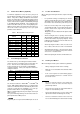
1.2 1.5 Internal Preset Memory Capability When setting up and using the monitor, keep the following in mind: • For optimum viewing, avoid placing the monitor against a bright background or where sunlight or other light sources may reflect on the display area of the monitor. Place the monitor just below eye level. • Place the monitor away from strong magnetic or electromagnetic fields, such as high capacity transformers, electric motors, large current power lines, steel pillars, etc....
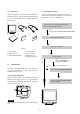
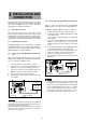
1.7 1.9 Quick Operation Chart Unpacking To summarize the steps in connecting your computer with the color monitor and setting the necessary controls and switches, refer to the chart below. After you unpack the box you should have all of the items indicated in Figure 1. Save the box and packing materials in case you transport the monitor. Complete and mail in warranty cards. 2 1 3 Connect the color monitor and computer with the necessary cords and cables. See Section 3.
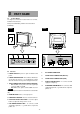
2 PART NAME ENGLISH 2.1 Control Names See Figures 3 and 4 for the location of the user controls, indicator and connectors. Each part is identified by number and is described individually. REAR FRONT D-SUB BNC A B 1 R G B COMP. HD VD 2 D-SUB BNC A B 1 R G B COMP. HD VD 2 Figure 4 Figure 3 2.2 Function 1. POWER SWITCH: A push-on / push-off switch for AC power. 2.
3 INSTALLATION AND CONNECTION On the back of the monitor four kinds of plug-in connections are provided: AC power connector for the AC input, DB915P connector and BNC connector for video signal input and USB ports for USB communication. 3.2.2 Connecting to An Apple Macintosh Computer 3.1 For Macintosh Adapter AD-A205, contact your dealer. Figure 6 shows the SC-B104 cable and AD-A205 Adapter(option) to the video port in an Apple Macintosh. AC Power Connection 1. 2.
3.2.3 Connecting to a Unix Workstation & Third Party Graphics Card 3.2.4 BNC Connection (1) COMPOSITE SYNC ON GREEN VIDEO SIGNAL (3 wires): Connect the R, G and B video signals to the BNC connectors on the back of the monitor. Figure 7 shows the SC-B104 or 75Ω coaxial cable (not supplied) connection to the graphics video card (PC-CAD and workstation). 3. 4. 5. BNC Power off, both the monitor and the computer.
3.4 Installation of USB Function (a) Disconnect and connect the USB cable to the upstream port of the display monitor. (b) Cycle power of the display monitor off then on. The following procedure permits your computer to recognize or "enumerate"(A USB term) the Mitsubishi USB HUB. 1. 2. Power on the display monitor and then the computer. NOTE If the mark appears with “Generic USB HUB”, then enumeration was unsuccessful. Select “Generic USB HUB” marked with mark and click “Remove” and “Refresh”.
(2) Click “Next” on Figure 11 and Figure 12 will appear. ENGLISH Figure 15 Figure 12 You can confirm that Enumeration of Mitsubishi Monitor Function is successfull with the following method. (3) Click “Next” on Figure 12 and Figure 13 will appear. • Open “Device Manager” tab in “System” property under “Control Panel”. Confirm that “HID-compliant Device” and “USB Human Interface Device” are listed in “Human Interface Device”.
4 4.1 OSD (On Screen Display) FUNCTIONS How to adjust the screen The monitor has an OSD(On Screen Display) function. The following procedure shows how to adjust the screen using the OSD function. (5)Adjust by pressing (1) Turn on the monitor. or button. (6)If you don't press any button for about ten seconds, the OSD screen will disappear. (2) Press button screen. The OSD can be turned off quickly by pressing button. to display the OSD (3) Select the group icon on Main Menu by pressing .
4.2 Adjustment Items X: Items Function Adjusts the contrast level. Adjusts the black level of the screen Select the desired color from Color 1, Color 2, and Color 3 presets. Adjusts the red-color balances for the selected color. Adjusts the green-color balances for the selected color. Adjusts the blue-color balances for the selected color. Adjusts the color temperature of the image on the screen. Restores the each color gain and color temperature to the factory preset.
Group Icon Item Icon Item CONTRAST BRIGHT Press the Minus Button Press the Plus Button To decrease the contrast. To increase the contrast. To decrease the brightness. To increase the brightness. COLOR NO To select color 1, color 2, color 3. R-GAIN To decrease red color level of the color mode selected by "COLOR NO". To increase red color level of the color mode selected by "COLOR NO". G-GAIN To decrease green color level of the color mode selected by "COLOR NO".
Group Icon Item Icon Press the Minus Button Press the Plus Button Item TEXT MODE To select "LOW" mode. To select "SMOOTH" mode. To select "HIGH" mode. HORIZ-CONVERGENCE To adjust the horizontal beam alignment on the full screen area. VERT-CONVERGENCE To adjust the vertical beam alignment on the full screen area. VERT-CONV-TOP To adjust the vertical beam alignment on the upper screen area. VERT-CONV-BOTTOM To adjust the vertical beam alignment on the lower screen area.
Group Icon Item Icon Item Press the Minus Button The USB functions of the computer connected to Upstream port ROOT-A become active. Press the Plus Button The USB functions of the computer connected to Upstream port ROOT-B become active. NOTE USB UP-STREAM The active Upstream port in active is colored blue on the OSD screen. In case that either the Upstream port ROOT-A or ROOT-B is chosen by this function, the auto-change of the Upstream port is not available.
5 TROUBLESHOOTING PROBLEM ITEMS TO CHECK LOCATION • Contrast and brightness controls. • Front (OSD) LED Off • Power switch. • AC power cord disconnected. • Front • Rear LED On (Amber) • Signal cable disconnected. • BNC cables are misconnected or the green cable is disconnected. • Computer power switch. • Power management function is active. • • • • Rear Check the graphics adapter and cables Computer Press any key on the keyboard or move the mouse. • Signal cable disconnected.
ITEMS TO CHECK PROBLEM LOCATION Abnormal Picture • Thin vertical black lines on one or both sides of the screen. This minor condition is caused by grille element overlap which can occur during shipping. Black vertical lines are visible on the screen. Two fine horizontal lines are visible on the screen. • – Position an open white window over the affected area of the screen and maximize the brightness and contrast controls.
6 SPECIFICATIONS Size CRT 55cm/22"(51cm/20" Diagonal Viewable Image) Mask type Aperture grille Gun In-line Deflection angle 90° Phosphors Red, Green, Blue EBU (medium short persistence) Aperture grille pitch 0.24mm Phosphor pitch 0.25mm Face Plate Focusing method Anti-glare, Anti-reflection and Anti-static coating Dynamic Beam Forming (DBF) INPUT SIGNAL Video Sync 0.7Vp-p analog RGB Sync. on Green or separate H, V sync.
7 7.1 APPENDIX 7.2 Monitor Signal Input Connector (DB9-15P) (Female) 5 DB9-15P 9 10 15 3 4 13 Approx. 1.8m 1 2 7 8 14 SC-B104 Signal Cable 2 1 6 12 6 11 12 MOUNTED ON THE REAR PANEL 4 3 9 8 7 11 13 5 10 14 15 DB9-15P(Male) DB9-15P(Male) PIN ASSIGNMENTS Pin No.
- 23 - 1,2 1,2 3,4 IIvi IIvx 3,4 1,2 2,4 1,2 3,4 2,4 2,3 3,4 2,4 3,4 1,2,3,4 1,2,3,4 1,2,3,4 2,3 2,4 1,2,6 1,2,6 1,2,6 1,2,6 3,4 1,2 3,4 1,2,6 2,4 3,4 1,2 3,4 1,2 3,4 3,4 1,2 3,4 Centris 610 650 1,2,6 1,2,6 1,2,6 1,2,6 1,2,6 1,2,6 1,2,6 1,2,6 1,2,6 3,4 1,2,6 1,2,6 1,2,6 3,4 3,4 3,4 1,2,6 3,4 6100 6100AV 8100 7100AV 6100AV 8100AV 7100AV AV 8100AV Video Card DRAM (DB-15) Video Port (HDI-45) 6410 Workgroup 8100 Server VRAM 6420 8150 Video Card 9150 (DB-15) Perfo
CP871C164A90 MITSUBISHI ELECTRIC CORPORATION HEAD OFFICE: MITSUBISHI DENKI BLD, MARUNOUCHI, TOKYO 100-8310 TELEX J24532 CABLE MELCO TOKYO http://www.mitsubishi-display.