• SAFETY PRECAUTIONS • (Read these precautions before using this product.) Before using this product, please read this manual and the relevant manuals carefully and pay full attention to safety to handle the product correctly. WARNING" and " CAUTION". In this manual, the safety precautions are classified into two levels: " Under some circumstances, failure to observe the precautions given under " CAUTION" may lead to serious consequences.
[Startup/Maintenance Instructions] ! CAUTION • The online operations performed from a PC to a running safety programmable controller (Program change when a safety CPU is RUN, device test, and operating status change between RUN and STOP) have to be executed after the manual has been carefully read and the safety has been ensured. Following the operating procedure predetermined at designing, the operation has to be performed by an instructed person.
• CONDITIONS OF USE FOR THE PRODUCT • (1) Mitsubishi programmable controller ("the PRODUCT") shall be used in conditions; i) where any problem, fault or failure occurring in the PRODUCT, if any, shall not lead to any major or serious accident; and ii) where the backup and fail-safe function are systematically or automatically provided outside of the PRODUCT for the case of any problem, fault or failure occurring in the PRODUCT.
REVISIONS The manual number is given on the bottom left of the back cover. Print Date Sep., 2006 Oct., 2007 Manual Number Revision SH(NA)-080576ENG-A First edition SH(NA)-080576ENG-B Addition Chapter 6 Correction GENERIC TERMS AND ABBREVIATIONS IN THIS MANUAL, Section 5.8 Mar., 2008 SH(NA)-080576ENG-C Jun., 2008 SH(NA)-080576ENG-D Correction Section 1.2.1, Section 1.2.2, Chapter 2, Section 5.5.2, Appendix 1 Correction Section 6.1.1 Apr., 2009 SH(NA)-080576ENG-E Apr.
INTRODUCTION Thank you for choosing the Mitsubishi MELSOFT series Integrated FA software. Please read this manual and make sure you understand the functions and performance of MELSEC series sequencer thoroughly in advance to ensure correct use. Please make this manual available to the end user. CONTENTS SAFETY PRECAUTIONS.............................................................................................................................A - 1 CONDITIONS OF USE FOR THE PRODUCT ........................
Chapter 5 ADDED FUNCTIONS TO CORRESPOND TO A SAFETY PROGRAMMABLE CONTROLLER 5- 1 to 5-50 5.1 Security Operations.................................................................................................................................. 5- 1 5.1.1 Registering the user when creating a new project ........................................................................... 5- 1 5.1.2 Registering/deleting/changing a login user ...............................................................................
MANUALS Introductory Manual Make sure to read the following manual before configuring/designing a safety system. Manual Name Safety Application Guide Explains the overview and construction method of the safety system, laying and wiring examples, application programs and others. (Sold separately.) Manual No. (Model Code) SH-080613ENG (13JR90) Related Manuals The following lists the manuals for this software package. Refer to the following table when ordering manuals. Manual Name Manual No.
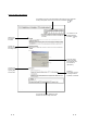
HOW TO SEE THE MANUAL The availability of the menu selection/operation, differs depend on the combination of safety CPU operation mode and an access level, is described. ( (1)) The restriction on the setting/operation is described. ( (1)) What to set in the section is described. Following the direction, open the setting screen. The screen for the setting is indicated. The numbered items are described in [Description]. The items and buttons numbered in [Dialog Box] are described.
(1) Availability of menu selection/operation (Upper right of the page) In each operation explained in the Chapter 5, the availability of the menu selection/operation, differs depend on the combination of safety CPU operation mode and an access level, is listed as the table below on the upper right corner of the first pages for each section. Admin. Safety CPU operation mode { Develop.
(3) Functions that cannot be operated by GX Developer The functions that cannot be operated using the GX Developer are grayed (masked) and cannot be selected. There are the following reasons why they are not selectable. (a) The programmable controller CPU used does not have the functions. For example, when the QSCPU is chosen in the "PLC series", selecting the [Project] [Change PLC type] is disabled since the QSCPU does not have another programmable controller type.
GENERIC TERMS AND ABBREVIATIONS IN THIS MANUAL This manual uses the abbreviations and generic terms listed in the following table to explain a software package and module such as programmable controller CPU. In addition, the following table lists the module model according to need.
MEMO A - 12 A - 12
1 GENERAL DESCRIPTION MELSOFT 1. GENERAL DESCRIPTION 1 This manual explains the added and updated GX Developer functions to support a safety programmable controller. Be sure to read this manual before using a safety programmable controller. For any unchanged functions, refer to the GX Developer Version 8 Operating Manual. 1.1 Features The following shows the features of the GX Developer supporting a safety programmable controller.
1 GENERAL DESCRIPTION MELSOFT 1.1.1 Access level 1 An access level designates the operation authority given to a user who logs in to a project. The access level is classified into the following three levels, in order from the highest level where all of operations are allowed to project data and a safety programmable controller. Access Level Operation Authority Administrators Can perform all operations. Only Administrators can perform user management and security settings.
1 GENERAL DESCRIPTION MELSOFT 1.1.2 User registration and login certification A safety programmable controller performs login certification when opening a project for the purpose of preventing unauthorized users from illegally accessing. (1) User registration A system manager has to define the person in charge, and then register the user information required for login certification with the project. The following information is required in user registration. 1) User name 2) Access level ( Section 1.1.
1 GENERAL DESCRIPTION MELSOFT 1.1.3 CPU access password A safety CPU performs access certification by using a password to prevent the misconnected GX Developer from illegally operating. The password is referred to a CPU access password. The CPU access password has to be set to both the GX Developer project and safety CPU. When performing the operation that changes control (e.g.
1 GENERAL DESCRIPTION MELSOFT 1.1.4 Safety CPU operation mode (SAFETY MODE and TEST MODE) A safety CPU operation mode includes a SAFETY MODE and TEST MODE. The safety CPU operation mode can be switched from the GX Developer. (1) SAFETY MODE The SAFETY MODE is used when operating a safety system. In this mode, the operations may lead a safety programmable controller to a control change (e.g. Write to PLC, Device test) are inhibited so that the running system is protected.
1 GENERAL DESCRIPTION MELSOFT 1.2 Functions Lists 1.2.1 Functions lists The GX Developer functions are listed below. (1) Common functions list The following shows the fixed functions independent of the editing and the type of setting target. Project (Common function) Only for monitoring 1 New project Open project Close project Save Save as Creates a new project. Opens the existing project. Closes an open project. Saves a project. Names and saves a project. Delete project Deletes the existing project.
1 GENERAL DESCRIPTION MELSOFT (Continued from the previous page.) Project (Common function) Only for monitoring 1 Macro Registration macros Macro utilize Delete macros Macro reference path Security operation User management Wait time settings Operation lock Printer setup Print Start new GX Developer session Exit GX Developer --- 3 --- ----------- --- --- --5.1.2 5.1.4 5.1.4 --Appendix 1 ----- Only for monitoring QSCPU Reference Registers/deletes/changes a login user.
1 GENERAL DESCRIPTION MELSOFT (Continued from the previous page.
1 GENERAL DESCRIPTION MELSOFT (Continued from the previous page.) Online (Common function) Only for monitoring 1 Safety CPU operation Switch safety CPU operation mode --- ROM information CPU access password registration/change PLC memory initialization Monitor destination select option Password Register password Delete password Disable password Clear PLC memory Format PLC memory Arrange PLC memory Set clock MELSECNET diagnostics Diagnoses the network. Diagnoses the CC-Link IE Controller Network.
1 GENERAL DESCRIPTION MELSOFT (Continued from the previous page.) Tools (Common function) Only for monitoring 1 Confirm project memory size Marge data Check parameter Transfer ROM Read Write Compare Write to file 2 Calculates the file size to be written to a programmable controller CPU. Merges data. Checks parameters.
1 GENERAL DESCRIPTION MELSOFT (Continued from the previous page.) Help (Common function) Only for monitoring 1 CPU error Special relay/register Key operation list Product information Connect to MELFANSweb Displays the description of each programmable controller CPU error code. Displays the description of special relays or special registers. Displays the description of each key operation. Displays product information such as a version number. Connects to the MELFANSweb.
1 GENERAL DESCRIPTION MELSOFT (2) Ladder editing functions list The following functions can be performed to edit ladders, operation outputs, and transition conditions. When installing the GX Developer with its functions limited, the ladder symbols can be used for searching. Project Only for monitoring Edit data New Copy Delete Rename Change program type Function Block Diversion Rename FB change module address --- --- --- --- ------------------- Diverts the FB to a ladder program.
1 GENERAL DESCRIPTION MELSOFT (Continued from the previous page.) Only for monitoring Edit 1 Ladder symbol --- QSCPU Reference 2 3 --- --- Open contact Inserts at the cursor position. --- Close project contact Inserts at the cursor position. --- Open branch Inserts at the cursor position. --- Close project branch Inserts at the cursor position. --- Coil Inserts at the cursor position. --- Application instruction Inserts at the cursor position.
1 GENERAL DESCRIPTION MELSOFT (Continued from the previous page.) Find/Replace Only for monitoring 1 Find device Find instruction Find step No. Find character string Find contact or coil Replace device Device block replacement Replace instruction Change open/close contact Replace character string Change module start address Replace statement/note type Cross reference window display Cross reference list List of used devices Converts a program. Converts all the programs (not converted yet) at a time.
1 GENERAL DESCRIPTION MELSOFT (Continued from the previous page.
1 GENERAL DESCRIPTION MELSOFT (Continued from the previous page.
1 GENERAL DESCRIPTION MELSOFT (3) Label program editing functions list The following functions can be performed to edit a label program. Project Only for monitoring Edit data New Copy Delete Rename Change program type Function Block Diversion Rename FB change module address --- --- --- --- ------------------- Diverts the FB to a ladder program. Renames the diverted FB. Sets the module start I/O No. used in FB definition.
1 GENERAL DESCRIPTION MELSOFT (Continued from the previous page.
1 GENERAL DESCRIPTION MELSOFT (4) Device comment editing functions list The following functions can be performed to edit device comments. Project Only for monitoring Edit data New Copy Delete Rename Change program type Function Block Diversion Rename FB change module address --- --- --- --- ------------------- Diverts the FB to a ladder program. Renames the diverted FB. Sets the module start I/O No. used in FB definition.
1 GENERAL DESCRIPTION MELSOFT (Continued from the previous page.
1 GENERAL DESCRIPTION MELSOFT (5) Device memory editing functions list The following functions can be performed to edit device memory. Project Only for monitoring Edit data New Copy Delete Rename Change program type Function Block Diversion Rename FB change module address --- --- --- --- ------------------- Diverts the FB to a ladder program. Renames the diverted FB. Sets the module start I/O No. used in FB definition.
1 GENERAL DESCRIPTION MELSOFT (Continued from the previous page.
1 GENERAL DESCRIPTION MELSOFT 1.2.2 Restricting operations by using safety CPU operation mode/access level This section explains the operability and restrictions of each GX Developer function differ depends on the combination of safety CPU operation mode and an access level.
1 GENERAL DESCRIPTION MELSOFT (Continued from the previous page.) SAFETY MODE Menu Item Admin. Develop. Users TEST MODE Admin. Develop.
1 GENERAL DESCRIPTION MELSOFT (Continued from the previous page.) SAFETY MODE Menu Item Admin. Develop. Users TEST MODE Admin. Develop. Restrictions Users Diagnostics PLC diagnostics Ethernet diagnostics CC IE Control diagnostics CC IE Field diagnostics MELSECNET diagnostics CC-Link / CC-Link/LT diagnostics System monitor Refer to Appendix 1. : Refer to 6. : Refer to 7. : Refer to 8. : Refer to 9. : Refer to 10. : Refer to 11.
1 GENERAL DESCRIPTION MELSOFT (2) Ladder editing functions Menu Item SAFETY MODE Admin. Develop. Users TEST MODE Admin. Develop.
1 GENERAL DESCRIPTION MELSOFT (Continued from the previous page.) SAFETY MODE Menu Item Admin. Develop. Users TEST MODE Admin. Develop. Users Find/Replace Find device Find instruction Find step No.
1 GENERAL DESCRIPTION MELSOFT (Continued from the previous page.) SAFETY MODE Menu Item Admin. Develop. Users TEST MODE Admin. Develop. Users Online Monitor Monitor mode Monitor (Write mode) Start monitor Stop monitor Change current value monitor (Decimal) Change current value monitor (Hexadecimal) Entry ladder monitor Delete all entry ladder Tools Check program Change display color : Can be operated. : Can be operated with restrictions. --: Can perform independent of the access level.
1 GENERAL DESCRIPTION MELSOFT (3) Label program editing functions Menu Item SAFETY MODE Admin. Develop. Users TEST MODE Admin. Develop.
1 GENERAL DESCRIPTION MELSOFT (4) Device comment editing functions SAFETY MODE Menu Item Admin. Develop. Users TEST MODE Admin. Develop. Users Restrictions ----------------------------------- Project Edit data New Copy Delete Rename Edit Cut Copy Paste Clear all (all devices) Clear all (displayed devices) Setup comment Setup comment range Find/Replace Find character string Replace character string : Can be operated. : Can be operated with restrictions.
2 SYSTEM CONFIGURATION MELSOFT 2. SYSTEM CONFIGURATION This section explains the system configuration to connect GX Developer and a safety CPU. For details of connection cable, refer to GX Developer Version 8 Operating Manual. 2 2.1 Connecting to Safety CPU The following explains the system configuration when GX Developer is connected to a safety CPU.
2 SYSTEM CONFIGURATION MELSOFT (3) Connecting via CC-Link IE Field Network Via CC-Link IE Field Network *1 Such as USB cable 2 QCPU LCPU Safety CPU CC-Link IE Field Network *2 GX Developer CC-Link IE Field NetworkBoard Safety CPU *1: For details of connecting a personal computer to each CPU, refer to (1) and (2) in this section, and the following manual. GX Developer Version 8 Operating Manual *2: For details, refer to the following manual.
3 COMMON OPERATIONS MELSOFT 3 RESTRICTIONS AND PRECAUTIONS 3.1 Precautions for the GX Developer Version Earlier than the Safety CPU Compatible Version (1) Precautions for saving and deleting a project When using the GX Developer whose version is earlier than the safety CPU compatible version (Version 8.39R or earlier), the login certification to a safety project cannot be performed to the following operations. Therefore, take care not to lose a safety project due to malfunctions.
3 COMMON OPERATIONS MELSOFT 3.2 Precautions for Management (1) Precautions for project data management Be sure to read the Safety Application Guide for correct management/operation of project data. A system manager has to back up the project and save the backup data so that the data restoration is always possible. (2) Precautions for password management A system manager has to manage the user information (e.g. user name, login password, and CPU access password) registered to a project with attention.
4 PROCEDURES TO OPERATION MELSOFT 4 PROCEDURES TO OPERATION This section explains the procedures from creating to operating a project for a safety programmable controller (Safety project). 4.1 When Creating a Safety Project The following shows the procedure from creating to operating the safety project. Creating the new project Reference 1) Create a new project. GX Developer Operating Manual 2) Register the user(s) whose access level is/are Administrators. Section 5.1.
4 PROCEDURES TO OPERATION MELSOFT 4.2 When Modifying the Safety Project in Operation The following shows the procedure from modifying the safety project in operation to operating the project. Open project Open the operating project. Reference Section 5.1.3 Changing the parameters and program Change the parameters and program. Reference GX Developer Operating Manual Switching to the TEST MODE 4 Switch the safety CPU operation mode to the TEST MODE. Reference Section 5.2.
5 ADDED FUNCTIONS TO CORRESPOND TO A SAFETY PROGRAMMABLE CONTROLLER MELSOFT 5 ADDED FUNCTIONS TO CORRESPOND TO A SAFETY PROGRAMMABLE CONTROLLER 5.1 Security Operations 5.1.1 Registering the user when creating a new project A system manager has to create a new project for a safety programmable controller. When creating a new project, the following screen appears. A system manager has to register the login user whose access level is Administrators.
5 ADDED FUNCTIONS TO CORRESPOND TO A SAFETY PROGRAMMABLE CONTROLLER 6) MELSOFT OK button Closes the screen when the setting is correct. The login to the project is performed with the registered user. In addition, the new user is registered with the User management screen described in Section 5.1.2. 7) Cancel button Cancels the setting and returns to the New Project screen. POINT For the additional registration of login users, refer to Section 5.1.2.
5 ADDED FUNCTIONS TO CORRESPOND TO A SAFETY PROGRAMMABLE CONTROLLER MELSOFT 5.1.2 Registering/deleting/changing a login user Admin. Develop. Users SAFETY TEST [Purpose] Registers/deletes/changes the login user of the project for a safety programmable controller. [Operating Procedure] Select [Project] [Security operation] [User management].
5 ADDED FUNCTIONS TO CORRESPOND TO A SAFETY PROGRAMMABLE CONTROLLER MELSOFT [Description] 1) User list/selection field • Display/Selection Displays the user names with their access levels registered with the project. Select the registered user to be deleted or the user whose information is to be changed. • Search Inputting the first character of a user name finds the user name(s) having the same first character.
5 ADDED FUNCTIONS TO CORRESPOND TO A SAFETY PROGRAMMABLE CONTROLLER MELSOFT (1) Adding a new user [Purpose] Adds the user who can log in to the project under editing. [Operating Procedure] Select [Project] [Security operation] [User management] Add button. [Dialog Box] 1) 2) 3) 5) 4) 6) 7) [Description] 1) User name Input a user name within 20 characters with the alphabets, numbers, and symbols corresponding to ASCII code ( Appendix 3) 20H to 7EH.
5 ADDED FUNCTIONS TO CORRESPOND TO A SAFETY PROGRAMMABLE CONTROLLER MELSOFT (2) Changing the registered user information [Purpose] Changes the registered user information. [Operating Procedure] Select [Project] [Security operation] [User management] Change button. [Dialog Box] 1) 2) 3) 4) 5) 6) [Description] 1) Title bar Displays the user whose information is to be changed. 2) User name Displays the user whose information is to be changed.
5 ADDED FUNCTIONS TO CORRESPOND TO A SAFETY PROGRAMMABLE CONTROLLER MELSOFT (3) Setting/changing a password [Purpose] Sets/changes the registered user password. [Operating Procedure] Select [Project] [Security operation] [User management] Password settings button. [Dialog Box] 1) 2) 3) 4) [Description] 1) New password Input a CPU access password within 6 to 14 characters with the alphabets, numbers, and symbols corresponding to ASCII code ( Appendix 3) 20H to 7EH.
5 ADDED FUNCTIONS TO CORRESPOND TO A SAFETY PROGRAMMABLE CONTROLLER MELSOFT (4) Copying user information [Purpose] Copies (Adds or overwrites) the user information registered with other project to the open project. [Operating Procedure] Select [Project] [Security operation] [User management] User copy button. [Dialog Box] Yes Select the original project in the screen above. POINT Copying user information • Selecting the original project displays the Login certification screen.
5 ADDED FUNCTIONS TO CORRESPOND TO A SAFETY PROGRAMMABLE CONTROLLER MELSOFT 5.1.3 Logging in to a project (1) Functions require login certification The following functions require login certification to the project for a safety programmable controller.
5 ADDED FUNCTIONS TO CORRESPOND TO A SAFETY PROGRAMMABLE CONTROLLER MELSOFT (3) Displaying login user information Login information is displayed on the bottom of the Project data list screen.
5 ADDED FUNCTIONS TO CORRESPOND TO A SAFETY PROGRAMMABLE CONTROLLER MELSOFT 5.1.4 Locking operations The GX Developer operations by other than the login users are inhibited. An operation lock has two types, automatic operation lock and manual operation lock. This section explains how to use the operation lock function. (1) Setting wait time for the automatic operation lock Admin. Develop. Users SAFETY TEST [Purpose] Sets the wait time to inhibit the GX Developer operations.
5 ADDED FUNCTIONS TO CORRESPOND TO A SAFETY PROGRAMMABLE CONTROLLER MELSOFT POINT • The wait time for the automatic operation lock is counted while the GX Developer has not been operated, and is reset when operating the GX Developer. However, the wait time is not reset in the following operations.
5 ADDED FUNCTIONS TO CORRESPOND TO A SAFETY PROGRAMMABLE CONTROLLER MELSOFT (2) Locking operation manually Admin. Develop. Users SAFETY TEST [Purpose] Manually locks operation when not operating the GX Developer. [Operating Procedure] Select [Project] [Security operation] [Operation lock]. [Dialog Box] Clicking the Yes button displays the Operation lock screen and locks the GX Developer operation.
5 ADDED FUNCTIONS TO CORRESPOND TO A SAFETY PROGRAMMABLE CONTROLLER MELSOFT (3) Unlocking an operation lock Admin. Develop. Users SAFETY TEST [Purpose] Unlocks an operation lock to enable the GX Developer operation. Only the users during login or whose access levels are Administrators can unlock the operation lock. [Dialog Box] After performing the operation lock, the following Operation lock screen appears. 1) 2) 3) [Description] 1) User name Input the user name who unlocks the operation lock.
5 ADDED FUNCTIONS TO CORRESPOND TO A SAFETY PROGRAMMABLE CONTROLLER MELSOFT 5.2 Safety CPU Operation 5.2.1 Switching safety CPU operation mode Admin. Develop. Users SAFETY TEST : Can perform only when the safety CPU is in STOP. [Purpose] Switches safety CPU operation mode (SAFETY MODE/TEST MODE). [Operating Procedure] Select [Online] [Safety CPU operation] [Switch safety CPU operation mode]. [Dialog Box] 1) 2) [Description] 1) Current operation mode Displays the current safety CPU operation mode.
5 ADDED FUNCTIONS TO CORRESPOND TO A SAFETY PROGRAMMABLE CONTROLLER MELSOFT 5.2.2 Displaying ROM information Admin. Develop. Users SAFETY TEST [Purpose] Displays the ROM information on a project and safety CPU. [Operating Procedure] Select [Online] [Safety CPU operation] [ROM information].
5 ADDED FUNCTIONS TO CORRESPOND TO A SAFETY PROGRAMMABLE CONTROLLER MELSOFT 2) Project information Displays the ROM information on the selected item. • When selecting "Currently edited information" Displays the parameter ID, program ID, and login user of the open project. 1 1: When a program is not created, the Program ID field is not displayed.
5 ADDED FUNCTIONS TO CORRESPOND TO A SAFETY PROGRAMMABLE CONTROLLER MELSOFT 5.2.3 Registering or changing a CPU access password Admin. Develop. Users SAFETY TEST : Registration to a safety CPU is disabled in the SAFETY MODE. Can perform in the TSET MODE only when a safety CPU is in STOP status. [Purpose] Registers the access password for certification (CPU access password) with a project and safety CPU. Matching the project password with the CPU access password enables the safety CPU operation.
5 ADDED FUNCTIONS TO CORRESPOND TO A SAFETY PROGRAMMABLE CONTROLLER MELSOFT (1) Password settings [Purpose] Sets a CPU access password to a project. [Operating Procedure] Select [Online] [Safety CPU operation] change] [CPU access password registration/ Password settings button. [Dialog Box] 1) 2) 3) 4) [Description] 1) New password Input a password within 6 to 14 characters with the alphabets, numbers, and symbols corresponding to ASCII code ( Appendix 3) 20H to 7EH.
5 ADDED FUNCTIONS TO CORRESPOND TO A SAFETY PROGRAMMABLE CONTROLLER MELSOFT (2) PLC register [Purpose] Registers the CPU access password set in a project with a safety CPU. [Operating Procedure] Select [Online] [Safety CPU operation] change] PLC register button. [CPU access password registration/ [Dialog Box] Clicking the Yes button registers the CPU access password set to the project with the safety CPU.
5 ADDED FUNCTIONS TO CORRESPOND TO A SAFETY PROGRAMMABLE CONTROLLER MELSOFT 5.2.4 PLC memory initialization Admin. Develop. Users SAFETY TEST : Can perform only when the safety CPU is in STOP. [Purpose] Initializes a safety CPU memory and returns it to the factory default. (Refer to the following table for the processing contents of the initialization.) [Operating Procedure] Select [Online] [Safety CPU operation] [PLC memory initialization].
5 ADDED FUNCTIONS TO CORRESPOND TO A SAFETY PROGRAMMABLE CONTROLLER MELSOFT 5.2.5 Switching the CPU to be monitored Admin. Develop. Users SAFETY TEST : Cannot perform during monitoring. [Purpose] Switches the CPU to be monitored for checking the information on "CPU A" or "CPU B" individually. The relevant functions are as follows.
5 ADDED FUNCTIONS TO CORRESPOND TO A SAFETY PROGRAMMABLE CONTROLLER MELSOFT 5.3 Detecting the Damaged Project Data The GX Developer checks that the project data for a safety programmable controller are not damaged before accessing it. This section explains about the target project data of damage detection, the target operation of damage detection, and the actions when damaged data are detected.
5 ADDED FUNCTIONS TO CORRESPOND TO A SAFETY PROGRAMMABLE CONTROLLER MELSOFT (3) Displays and actions when damaged data are detected The following shows the display screens and actions when damaged data are detected. (a) Display screen (b) Action • Click the OK button. • If the data is backed up, restore the project from the backup data. • If the data is not backed up, recreate the project. ( Section 5.1.1) POINT When damaged project data is detected, restoring it from the backup data is recommended.
5 ADDED FUNCTIONS TO CORRESPOND TO A SAFETY PROGRAMMABLE CONTROLLER MELSOFT 5.4 Highlighting Safety Devices Admin. Develop. Users SAFETY TEST 5.4.1 Safety devices (1) Safety device in CC-Link safety The safety device designates the refresh device of the remote I/O in safety remote station. The refresh device ranges for the number of occupied station in safety remote station (occupies 32 points/station) is used for safety devices.
5 ADDED FUNCTIONS TO CORRESPOND TO A SAFETY PROGRAMMABLE CONTROLLER MELSOFT (2) Safety device in CC-Link IE Field Network A device which is set in the receive data storage device/send data storage device of the safety communication setting is called safety device. The safety communication setting can be set when selecting "CC IE Field (Master station [Safety]) " or "CC IE Field (Local station [Safety])" for network type.
5 ADDED FUNCTIONS TO CORRESPOND TO A SAFETY PROGRAMMABLE CONTROLLER MELSOFT POINT • When a label program is not compiled, the safety devices are not highlighted. • The program can be printed for highlighting ( Appendix 1). • When using the instruction which processes word devices with multiple points, the safety device is not highlighted if the safety device(s) is/are included but the device specified as the argument to the instruction is not a safety device.
5 ADDED FUNCTIONS TO CORRESPOND TO A SAFETY PROGRAMMABLE CONTROLLER MELSOFT 5.5 Setting Parameters Admin. Develop. Users SAFETY TEST This section explains the setting items for safety CPU parameters. For basic operations and common notes in the parameter setting screen, refer to GX Developer Version 8 Operating Manual. 5.5.1 Setting PLC parameters (1) PLC parameter items list The following shows the PLC parameter items list.
5 ADDED FUNCTIONS TO CORRESPOND TO A SAFETY PROGRAMMABLE CONTROLLER MELSOFT 5.5.2 Setting network parameters The following shows the network parameter items list. For information and details required for the parameter settings, refer to the user's manual of the corresponding network module.
5 ADDED FUNCTIONS TO CORRESPOND TO A SAFETY PROGRAMMABLE CONTROLLER MELSOFT (3) Network parameter items of CC-Link Safety CC-Link No. of boards in module Set the number of modules (1 or 2 modules). Start I/O No. Set the start I/O No. Operational setting Set "Parameter name" and "Case of CPU STOP setting". Station No. Set the number of remote station for which a loop test is performed. Master station data link type The setting is fixed to "PLC parameter auto start". Mode Set the mode.
5 ADDED FUNCTIONS TO CORRESPOND TO A SAFETY PROGRAMMABLE CONTROLLER MELSOFT POINT • Information and details required for the parameter settings For information and details required for the parameter settings, refer to the following manuals.
5 ADDED FUNCTIONS TO CORRESPOND TO A SAFETY PROGRAMMABLE CONTROLLER MELSOFT (4) Network parameter items of CC-Link IE Field Network CC-Link IE Field Network type Specify the CC-Link IE Field (Master station [Safety]), CC-Link IE Field (Local station [Safety]) or CC-Link IE Field (Local station). Starting I/O No. Set the first I/O No. Network No. Set the network No. Total stations Set the total number of (slave) stations. Station No. Set the station number. Mode Set the mode.
5 ADDED FUNCTIONS TO CORRESPOND TO A SAFETY PROGRAMMABLE CONTROLLER MELSOFT (5) Network parameter items of CC-Link IE Controller Network CC-Link IE Controller Network Network type Set the CC-Link IE Control (Normal station). Starting I/O No. Set the first I/O No. Network No. Set the network No. Group No. Set the group No. Station No. Set the station number. Mode Set the mode. Refresh parameters Set the refresh parameters. (Max. 64) Station No.
5 ADDED FUNCTIONS TO CORRESPOND TO A SAFETY PROGRAMMABLE CONTROLLER MELSOFT 5.6 Diagnosing a Safety Programmable Controller 5.6.1 Diagnosing a safety CPU Admin. Develop. Users SAFETY TEST : Cannot use "Clear log". [Purpose] Checks safety CPU operation status, a present error, and operation/error logs (Including the error log of a CC-Link Safety system). The display contents of operation/error logs can be saved in a CSV file. [Operating Procedure] Select [Diagnostics] [PLC diagnostics].
5 ADDED FUNCTIONS TO CORRESPOND TO A SAFETY PROGRAMMABLE CONTROLLER MELSOFT 3) Monitor run/stop Clicking the Start monitor button initiates communications with a safety CPU and updates the screen display. Clicking the Stop monitor button stops monitoring. 4) Operation/error log Displays the logs of the operation to a safety CPU and error occurred in a safety CPU. 5) Display filter Specify the log type to be displayed on the log list.
5 ADDED FUNCTIONS TO CORRESPOND TO A SAFETY PROGRAMMABLE CONTROLLER MELSOFT • Error details screen Displays common error information and individual error information, based on the information stored in the SD4 and SD5 or later of a safety CPU. For details of common error information and individual error information, refer to the QSCPU User's Manual (Function Explanation, Program Fundamentals).
5 ADDED FUNCTIONS TO CORRESPOND TO A SAFETY PROGRAMMABLE CONTROLLER MELSOFT 7) Occurrence order display Sorts the log list in ascending/descending order. 8) Update log button Updates the log list with the radio button. Radio Button 32 items All items 9) Log List display Displays the latest 32 logs. Displays all the registered logs (Max. 3000 logs). Clear log button Deletes all the logs registered with a safety CPU. Logs can be deleted in the following situations.
5 ADDED FUNCTIONS TO CORRESPOND TO A SAFETY PROGRAMMABLE CONTROLLER MELSOFT 5.6.2 Diagnosing CC-Link IE Field Network CC-Link IE Field Network diagnostics performs the network status check and the troubleshooting when starting CC-Link IE Field Network, and performing maintenance/operation. CC-Link IE Field Network diagnostics executes when transfer target is own station QSCPU, and network module mode is online or loop test.
5 ADDED FUNCTIONS TO CORRESPOND TO A SAFETY PROGRAMMABLE CONTROLLER MELSOFT (2) Diagnostic screen Admin. Develop. Users SAFETY TEST : Cannot set the station number for number unspecified station [Purpose] Check the status of disconnected cable and disconnected station on the network configuration diagram that displays the current status of CC-Link IE Field Network. Open screens such as "Operation Test" for troubleshooting and the "Information Confirmation/Set" with buttons.
5 ADDED FUNCTIONS TO CORRESPOND TO A SAFETY PROGRAMMABLE CONTROLLER MELSOFT 3) Network Status Displays the total number of slave stations, the link scan time (in units of ms), and the number of stations error occurs on the network being displayed. 4) Legends button Displays the explanation for icons displayed on the diagnostics screen. 5) Network configuration Displays the state of the network. The status of stations is displayed with icon.
5 ADDED FUNCTIONS TO CORRESPOND TO A SAFETY PROGRAMMABLE CONTROLLER MELSOFT 6) Selected Station Communication Status Monitor Displays the communication status of the own station. The following explains the display that is given if an error occurs with the CCLink IE Field Network module or in the connection cable. In this case, a button is displayed in "Selected Station Communication Status Monitor" as shown below.
5 ADDED FUNCTIONS TO CORRESPOND TO A SAFETY PROGRAMMABLE CONTROLLER MELSOFT Communication Test button 7) Displays the Communication Test screen. ( (3) in this section) 8) Cable Test button Displays the Cable Test screen. (4) in this section) ( 9) Link Start/Stop button Displays the Link Start/Stop screen. ( (5) in this section) 10) Network Event History button Displays the Network Event History screen.
5 ADDED FUNCTIONS TO CORRESPOND TO A SAFETY PROGRAMMABLE CONTROLLER MELSOFT (3) Communication Test Admin. Develop. Users SAFETY TEST [Purpose] Executes the communication test between CC-Link IE Field Networks. [Operating Procedure] Select [Diagnostics] [CC IE Field Diagnostics] Communication Test button.
5 ADDED FUNCTIONS TO CORRESPOND TO A SAFETY PROGRAMMABLE CONTROLLER MELSOFT (4) Cable Test Admin. Develop. Users SAFETY TEST [Purpose] Tests the cable connection status between testing station and equipment connected to the testing station port. [Operating Procedure] Select [Diagnostics] [CC IE Field Diagnostics] Cable Test button. [Dialog Box] 1) 2) 3) [Description] 1) Testing Station Setting Set the network number and station number of the station which executes the cable test.
5 ADDED FUNCTIONS TO CORRESPOND TO A SAFETY PROGRAMMABLE CONTROLLER MELSOFT (5) Link Start/Stop Admin. Develop. Users SAFETY TEST : Cannot execute link start/stop, forced link start [Purpose] Executes data link start/stop to the specified station. Disable receiving data from other stations and sending data of the own station in the case of such as debugging. [Operating Procedure] Select [Diagnostics] [CC IE Field Diagnostics] Link Start/Stop button.
5 ADDED FUNCTIONS TO CORRESPOND TO A SAFETY PROGRAMMABLE CONTROLLER MELSOFT (6) Network Event History Admin. Develop. Users SAFETY TEST : Cannot perform clearing network event history, setting history acquisition [Purpose] The history list of events which occurred in own station or the networks is displayed. The display contents of network event history logs can be saved in a CSV file. [Operating Procedure] Select [Diagnostics] [CC IE Field Diagnostics] Network Event History button.
5 ADDED FUNCTIONS TO CORRESPOND TO A SAFETY PROGRAMMABLE CONTROLLER MELSOFT (7) Reserved Station Function Enable Admin. Develop. Users SAFETY TEST : Cannot perform temporary cancellation of a reserved station/restoring the reserved station. [Purpose] Temporarily cancels the reserved station/restores the reserved station. If connected to a local station, cannot execute the temporarily cancellation/restoration of the reserved station.
5 ADDED FUNCTIONS TO CORRESPOND TO A SAFETY PROGRAMMABLE CONTROLLER MELSOFT (8) Temporary Error Invalid Station Setting/Restore Admin. Develop. Users SAFETY TEST : Cannot perform temporary error invalid station setting /restoring temporary error invalid station setting [Purpose] Sets/restores the temporary error invalid station. If connected to a local station, cannot execute the temporary error invalid station setting/restoration.
5 ADDED FUNCTIONS TO CORRESPOND TO A SAFETY PROGRAMMABLE CONTROLLER MELSOFT 5.7 Writing Program Memory to ROM Admin. Develop. Users SAFETY TEST [Purpose] Writes the data in program memory to standard ROM at a time. [Operating Procedure] Select [Online] [Write to PLC (Flash ROM)] ROM]. [Write the program memory to [Dialog Box] 2) 1) [Description] 1) Target Only "Standard ROM" is displayed (Fixed). 2) Execute button Writes the data in program memory to standard ROM at a time.
5 ADDED FUNCTIONS TO CORRESPOND TO A SAFETY PROGRAMMABLE CONTROLLER MELSOFT 5.8 Checking Devices for Duplication Use Admin. Develop. Users SAFETY TEST [Purpose] Checks if devices in the range set in Auto device setting are not used in the usercreated program during program check. [Operating Procedure] Select [Tools] [Check program] or .
6 SAFETY FUNCTION BLOCK MELSOFT 6 SAFETY FUNCTION BLOCK The safety function block represents safety control logic in function block for easier creation of a safety program. The safety function has the following features. (1) Creating safety program easily Basic safety ladders are provided as safety function blocks. Using safety function blocks can create safety programs easily and surely.
6 SAFETY FUNCTION BLOCK MELSOFT 6.1 Programming Using Safety Function Blocks The following flowchart shows creating procedure of the program using safety function blocks. 6 6-2 Create "Use labels" project. (Or open the existing "Use labels" project.) GX Developer Version 8 Operating Manual Incorporate safety function blocks in the project. Section 6.1.1 Paste safety function blocks to the sequence program. Section 6.1.
6 SAFETY FUNCTION BLOCK MELSOFT 6.1.1 Incorporating safety function blocks in a project Admin. Develop. Users SAFETY TEST [Purpose] Incorporates safety function blocks to the project by copying them from the safety function library. [Operating Procedure] Select [Project] [Copy]. [Dialog Box] 1) 2) 3) [Description] 1) Drive/Path name, Project name Set the drive/path and project names. The safety function library is installed to the following folder when GX Developer is installed.
6 SAFETY FUNCTION BLOCK MELSOFT POINT y If the safety function block having the same name exists on the open project, it is overwritten. y To open the safety function library, perform the following procedure. 1) Select [Project] [Copy]. Enter the following in the screen below. Version 1 : "(Installed location)\GPPW\FB-Library\Safety" Version 2 : "(Installed location)\GPPW\FB-Library\SafetyV2" "_all" 2) The following screen appears. Input "SafetyFB" in "User name".
6 SAFETY FUNCTION BLOCK MELSOFT 6.1.2 Pasting safety function blocks to the sequence program Paste function blocks to the sequence program. The following three methods are available for pasting the function blocks. For details of each pasting method, refer to the GX Developer Version 8 Operating Manual (Function Block).
6 SAFETY FUNCTION BLOCK MELSOFT 6.1.3 Checking I/O variables for safety function block Check I/O variables to create input ladder section/output ladder section of the safety function block pasted to the sequence program. Add other ladders to the safety function block on which input ladder section and output ladder section were created, and complete the sequence program. For editing a program, refer to the GX Developer Version 8 Operating Manual.
6 SAFETY FUNCTION BLOCK MELSOFT 6.2 Restricting the Safety Function Block Operations/Displays Some operations/displays of the safety function blocks are restricted for safety assurance. The following table shows restrictions on operation/display in each function. Function/screen Restrictions on operation/display Project data list <> tab Only FB definition name is displayed at the tree item of the safety function block. Double-clicking the FB definition name displays the FB variable window.
6 SAFETY FUNCTION BLOCK Function/screen MELSOFT Restrictions on operation/display Device display screen As for safety function block, only FB definition name is displayed in application 1 instruction format. The program contents of the safety function block are not displayed. Verify In a program including a safety function block, the program contents in the safety function block are not displayed.
6 SAFETY FUNCTION BLOCK MELSOFT MEMO 6-9 6-9
APPENDICES MELSOFT APPENDICES Appendix 1 Differences with the Q Series Project This chapter explains about the GX Developer functions, except for the functions described in Chapter 5 "ADDED FUNCTIONS TO CORRESPOND TO A SAFETY PROGRAMMABLE CONTROLLER", added to/updated from the Basic model QCPU project (1) Differences with the parameters (a) [PLC RAS] setting on PLC parameter. Consistency check for setting time on WDT setting and constant scanning.
APPENDICES MELSOFT • Print example of "Safety remote station settings" The following shows the print example when the "Safety remote station settings" is being performed under the settings as the screen below.
APPENDICES MELSOFT 2) Safety device names are printed enclosed by a solid line or broken line. Device Type Bit device Highlighting Description The safety device names are printed enclosed by a solid line. Word device bit specification The safety device names are printed enclosed by a solid line. Word device When all the bits specified by digit specification are safety devices, the safety device names are printed enclosed by a solid line.
APPENDICES MELSOFT (3) Differences in the Online menu (a) Transfer setup The connection via CC-Link IE Field Network can be set. Connectable CPU to software package and the combination of networks are as shown below. Connection destination CPU and its network Software package PC side I/F QSCPU Other than QSCPU CC-Link IE Field Network QSCPU Other than QSCPU Other than CC-Link IE Field Network QSCPU GX Developer Other than QSCPU QSCPU GX Works2 (GX Works2 is not supported by QSCPU.
APPENDICES MELSOFT (d) Remote operation To perform the remote RUN while the safety CPU operation mode is set to SAFETY MODE, make the following settings. "Operation during RUN" setting items Device memory: Not cleared Signal flow: Hold (e) Change TC setting Setting values of counter/timer cannot be changed more than 32.
APPENDICES MELSOFT The No button: Suspends the processing. The Yes button: Forcibly performs the processing. In this case, other GX Developer’s processing has been stopped and the following message appears. (4) Differences in the Diagnostics menu (a) PLC diagnostics The PLC diagnostics screen displays the "CPU A" or "CPU B" information in a safety CPU selected in the Monitor destination select option screen.
APPENDICES MELSOFT (c) CC IE Control diagnostics The following function cannot be used. • Link start/stop • Communication test (d) Ethernet diagnostics The following functions cannot be used.
APPENDICES MELSOFT (e) CC-Link / CC-Link/LT diagnostics • Network test cannot be performed. • "Invalid station if temporary error" in the CC-Link / CC-Link/LT diagnostics (Other station) screen cannot be set.
APPENDICES MELSOFT (5) Differences in the Tool menu (a) Merge data The program or comment data created in a safety programmable controller project can only be merged with (a) safety programmable controller project(s). (b) Options <> tab The following items cannot be selected for a safety CPU. • Statement insertion method • Step No.
APPENDICES MELSOFT <> tab For a safety CPU, the "Device comment" field is fixed to "Comment for each program". <> tab For a safety CPU, "All common data" and "Extended setting" cannot be selected. <> tab Since a safety CPU does not support the TEL function, the <> tab cannot be displayed.
APPENDICES MELSOFT Appendix 2 Functions for which CPU Access Password Certification is Performed CPU access password certification is performed when the safety CPU status is to be changed by the GX Developer operation. Note when reading data from a safety CPU (e.g. Read from PLC, monitor), the CPU access password certification is not performed. The following shows the GX Developer functions for which the CPU access password certification is performed.
APPENDICES MELSOFT Appendix 3 ASCII Code Table MSD LSD Appendix - 12 0 1 2 3 4 5 6 7 000 001 010 011 100 101 110 111 0 0000 NUL DLE (SP) 0 @ P ` p 1 0001 SOH DC1 ! 1 A Q a q 2 0010 STX DC2 “ 2 B R b r 3 0011 ETX DC3 # 3 C S c s 4 0100 EOT DC4 $ 4 D T d t 5 0101 ENQ NAK % 5 E U e u 6 0110 ACK SYN & 6 F V f v 7 0111 BEL ETB ‘ 7 G W g w 8 1000 BS CAN ( 8 H X h x 9 1001 HT EM ) 9 I Y I y A 10
INDEX IND [O] [A] Access level................................................... 1- 2 ASCII Code Table .....................................App-12 Operation/error log.........................................5-34 Operation lock ................................................1- 5 [C] Checking devices for duplication use ........... 5-49 Checking safety function block variable ....... 6- 5 Copying user information .............................. 5- 8 CPU access password..................................
MEMO Index - 2 IND Index - 2
Microsoft, Windows, Windows NT, Windows Vista are registered trademarks of Microsoft Corporation in the United States and other countries. Pentium is a registered trademark of Intel Corporation in the United States and other countries. Other company and product names herein are either trademarks or registered trademarks of their respective owners. SPREAD Copyright (C) 1998 Farpoint Technologies, Inc.