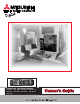
AD Projection Television Models WS-B55 WS-48511 WS-55511 WS-55711 WS-65511 WS-65611 WS-65711 WS-65712 WS-73711 JU ST Owner’s Guide visit our website at w w w. m i t s u b i s h i - t v.
CAUTION RISK OF ELECTRIC SHOCK DO NOT OPEN CAUTION: TO REDUCE THE RISK OF ELECTRIC SHOCK, DO NOT REMOVE COVER (OR BACK). NO USER SERVICEABLE PARTS INSIDE. REFER SERVICING TO QUALIFIED SERVICE PERSONNEL. The lightning flash with arrowhead symbol within an equilateral triangle is intended to alert the user of the presence of uninsulated “dangerous voltage” within the product’s enclosure that may be sufficient magnitude to constitute a risk of electric shock.
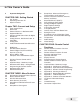
In This Owner’s Guide 4 Important Safeguards CHAPTER ONE: Getting Started 8 9 9 Our Thanks Unpacking Your New TV Special Features Chapter TWO: Connect and Setup 12 13 15 16 17 17 19 20 21 21 22 23 24 24 25 26 27 28 32 Front Control Panel Back Panel External Devices & NetCommand™ Supported Devices Antenna or Wall Outlet Cable for Digital Broadcasts Analog Antenna, Wall Outlet Cable, or Cable Box Analog VCR Audio/Video Surround Sound Receiver DVD Player S-Video Satellite Receiver External Digital TV (DTV
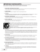
IMPORTANT SAFEGUARDS Please read the following safeguards for your TV and retain for future reference. Always follow all warnings and instructions marked on the television. 1. Read, Retain and Follow All Instructions Read all safety and operating instructions before operating the TV. Retain the safety and operating instructions for future reference. Follow all operating and use instructions. 2. Heed Warnings Adhere to all warnings on the appliance and in the operating instructions. 3.
IMPORTANT SAFEGUARDS, cont’d. 12. Power Lines An outside antenna system should not be located in the vicinity of overhead power lines or other electric light or power circuits, or where it can fall into such power lines or circuits. When installing an outside antenna system, extreme care should be taken to keep from touching such power lines or circuits as contact with them might be fatal. 13.
If you have questions regarding your television, call Consumer Relations at (800) 332-2119, or email us at MDEAservice@bigscreen.mea.com To order replacement or additional remote controls or owner’s guides call (800) 553-7278 or visit our website at w w w. m i t s u b i s h i - t v.
In This Section . . .
Our Thanks... Thank you for choosing Mitsubishi as your premier Home Entertainment provider. This Owner’s Guide describes the features and functions of your Mitsubishi widescreen, high definition TV. We urge you to examine this Owner’s Guide to become familiar with the innovative features and operations this unique television offers. The very core of our corporate philosophy is to provide our customers with the very best.
Unpacking Your New TV Please take a moment to review the following list of items to ensure that you have received everything included: � Remote Control � (2) AA Batteries � (1) Digital Audio Cable 4 (1) Double IR Emitter Cable 5 (1) Quadruple IR Emitter Cable 6 Product Registration Card 7 Owner’s Guide 8 Quick Reference Card � NetCommand™ 2.0 Guide Special Features Your new High Definition bigscreen television has many special features that make it the perfect center of your home entertainment system.
In This Section . . .
Front Control Panel ������ ����� ����� ����� ��� �� ����� ���� ��� ����� ������ ������ ����� ���� ������ ������� ������ ����� � � ����� � � ����� � ����� ����� ������� ��������� ��������� ��������� ��������� ��������� �������� ����� � ����� ����� �������� ������ ����� ����� ��� �� ����� ���� ����� ���� ��� ����� ������� ������ ����� � � ����� � ����� � ����� ������ ������ ������ ��������� ��� ���� �� ������� ����� ����� ����� �������� The buttons on the Front Control P
Back Panel � Inputs 1-4 These inputs can be used for the connection of a VCR, Super VHS (S-VHS) VCR, DVD player, standard satellite receiver or other A/V device to the TV. Please note that if you connect to the S-VIDEO terminal, the VIDEO terminal is deactivated. The VIDEO terminal is active when there is no S-Video connection. � Output (Monitor and PIP) The Monitor Output sends the TV audio and video signals from Ant-A, Ant-B and Inputs 1-5 to an A/V Receiver or other analog A/V equipment.
Back Panel 8 Antenna DTV (ANT-DTV) This input receives digital TV signals from a VHF/UHF antenna or unscrambled digital cable system. If the TV receives scrambled cable signals on this input, it will not be able to decode them. In this case, your cable company must provide a decoding box. 9 IEEE-1394 Input/Output These jacks allow the TV to connect to one or more external digital products by means of a single cable.
Connecting External Devices & NetCommand™ Setup NetCommand™ is able to control many current audio and video devices by sending remote control signals from the TV to each device. NetCommand™ will also automatically switch the TV and compatible Audio/ Video (A/V) Receivers to the correct input used with each device. It is important that the inputs on the TV and AV Receiver match the NetCommand™ Setup. To simplify the installation of NetCommand™, there is a step-by-step on-screen NetCommand™ Setup procedure.
NetCommand™ Supported Devices Following is a list of devices, by several manufacturers, tested and shown to be compatible with the NetCommand™ control system. When you use these devices you will be able to control them without changing the setting of the remote control from TV to another product.
Connecting Antenna or Wall Outlet Cable for Digital Broadcasts Figure 1. Antenna or wall outlet cable. Antenna or Wall Outlet Cable for Digital Broadcasts For cable or antenna with coaxial lead (Figure 1) 1. Connect the incoming cable to ANT-DTV on the TV back panel. IMPORTANT Additional connection cables are not provided with the TV. They are available at most electronic stores. Mitsubishi strongly recommends against using antennas with twin flat leads.
Connecting an Analog Antenna, Wall Outlet Cable, or Cable Box, cont’d. Antenna or Wall Outlet Cable for Analog Broadcasts. (Figure 2) For antennas with twin flat lead 1. For antenna with twin flat leads, connect the 300Ohm twin leads to the transformer. 2. Push the 75-Ohm side of the transformer onto ANT-A on the TV back panel. Note: 300-Ohm to 75-Ohm matching transformers are not provided with the TV. They should be available at most electronic stores. For cable or antenna with coaxial lead 3.
Connecting an Analog VCR VCR to Analog Antennas or Wall Outlet Cable (Figure 1) 1. Connect the incoming cable to ANT-A on the TV back panel. Note: Connect two coaxial cables as follows: 2. One from LOOP-OUT on the TV back panel to ANTENNA IN on the VCR back panel. 3. One from VCR back panel ANTENNA OUT to ANT-B on the TV back panel. 4. Now complete Figure 3, steps 1-2. VCR to Cable Box (Figure 2) Figure 1. Connecting VCR with antennas or wall outlet cable.
Connecting an Audio/Video Surround Sound Receiver Connecting an A/V Receiver (Figure 1) When you connect a digital A/V Receiver with Dolby Digital TM surround sound: 1. Connect a video cable from Monitor VIDEO OUTPUT on the back of the TV to the TV VIDEO INPUT on the back of the A/V Receiver. 3. Connect one end of the digital audio cable supplied with the TV to the DIGITAL AUDIO OUTPUT on the back of the TV (connect the end of the cable with the ferrite or plastic cylinder).
WARNING: Do not display the same stationary images on the screen for more that 15% of your total TV viewing in one week. Examples of stationary images are letterbox top/bottom bars from DVD or other video sources, side bars when showing standard TV pictures on widescreen TV’s, stock market reports, video game patterns, station logos, black or bright Closed caption backgrounds web sites, or stationary computer images. Such patterns can unevenly age the picture tubes causing permanent damage to the TV.
Connecting an External Digital TV (DTV or HDTV) Receiver DTV Connectors and Adaptors (Figure 1) The TV back panel has 5 RCA-type connectors for the Input-DTV. The back panel of your external DTV receiver may use RCA-type connectors or BNC-type connectors. If your DTV receiver comes with BNC type connections, you will need to purchase BNC to RCA adaptors to connect the TV to the DTV receiver. These adaptors should be available at most electronic supply stores.
Connecting an External Digital TV (TV or HTV) Receiver, cont. External DTV Receiver with RGB Video Connections (Figure 1) IMPORTANT • See Appendix B for RGB video signal compatibility information. • For digital audio connections, see your DTV Receiver and A/V Receiver Owner’s Guides. 1. Connect the outside antenna, cable, or satellite to ANT, or SATELLITE IN on the DTV receiver (see your DTV receiver owner’s guide for instructions, and cable compatibility). 2.
Connecting a Computer with a VGA Monitor Output Connecting a Computer (Figure 1) 1. Connect VGA Monitor Out from the computer to VGA Input on the TV back panel using a VGA compatible monitor cable. See Appendix B for VGA signal compatibility. 2. Connect the L (left) and R (right) audio cables from the computer to VGA AUDIO on the TV back panel. In cases where your computer’s audio output is a single mini- jack, a splitter is needed to complete this connection.
IMPORTANT NOTES WARNING: When using the VGA input, do not leave stationary, toolbar, or partial images on-screen for extended periods of time. Mix the types of pictures shown. Uneven picture tube aging is NOT covered by your warranty.
NetCommand™ Setup - Getting Started In order to use your TV’s NetCommand™ feature, you need to provide some detailed information during the setup of your Mitsubishi TV. You must define the Manufacturer of the devices that are connected to the television. For each device, the input to the TV and A/V receiver, and the names for the device are pre-set during Initial NetCommand™ setup. You may change those inputs or names using the Edit NetCommand™ screen.
Programming the Remote Control to Control NetCommand™ NetCommand™ CODE to ENTER TV Control and NetCommand™ Devices: 935 To Program the Remote to Control the TV and NetCommand™ A/V Products: (See NetCommand™ Supported Devices, for the list of A/V products supported by the NetCommand™ System.) 1. Move the slide switch at the top of the remote to the TV layer. Figure 1. Programming the TV remote to control your NetCommand™ A/V devices. 2. Press and hold the POWER button on the remote control. 3.
NetCommand™ Setup When you first power On your new Mitsubishi TV, the initial setup screens will appear. You will need to navigate through these screens and properly set up the equipment connected to the TV in order to use NetCommand™. NetCommand™ supports the automatic switching of audio and video inputs using only the TV Remote Control. IMPORTANT You may use your TV without setting up NetCommand™.
NetCommand™ Setup, cont’d. A/V Receiver Screen Figure 1 Figure 1. A/V Receiver screen. The A/V Receiver screen allows you to select the manufacturer of the A/V Receiver you are currently using. When a compatible model is used, NetCommand™ will be able to change inputs and adjust volume on the A/V Receiver. The bottom of the screen shows the model optimized for NetCommand™. Other models from the same manufacturer are often compatible.
NetCommand™ Setup, cont’d. DBS Screen Figure 1 The DBS (Digital Broadcast Satellite) screen allows you to select the manufacturer of the satellite system you are currently using. If “Other” is selected for the Manufacturer, then NetCommand™ can not control the device (use the layer switch on the remote or use the remote for the device). The bottom of the screen shows the model optimized for NetCommand™ programming. Other models from the same manufacturer are often compatible.
NetCommand™ Setup, cont’d. Review Screen Figure 1 Figure 1. Review screen. Once you have finished the setup screens and selected the manufacturer for each device, you will see the Review Screen. It is important to review the settings. If necessary, you can navigate back through the NetCommand™ Setup screens to make changes. On this screen, adding or deleting check marks will turn On or Off the adjacent Input or Device. Note: The Review screen lists TV and A/V Receiver inputs used with each device.
Edit NetCommand™ Realizing your home theater system will continually change as you add and remove components, Mitsubishi’s NetCommand™ also offers ease of use when it comes to editing your home theater configuration. Edit NetCommand™ Screen Figure 1 When you need to make a change to your current setup, the Edit NetCommand™ screen makes it easy. Possible choices, although not always available, are Add, Change, Delete, Review, or Initial. Figure 1. Edit NetCommand™ screen .
Edit NetCommand™, cont’d. Delete Figure 1 Figure 1. Delete screen. When you select Delete from the Edit NetCommand™ Screen, you will see the Delete Screen. You can choose to delete just a single device by selecting the device you would like to delete, or you can delete the entire NetCommand™ configuration. After you have chosen the device, or the Entire Configuration, you will be prompted to confirm your choice to delete.
Edit NetCommand™, cont’d. The following screens are a part of the Add device or Change device modes. Name Screen Figure 1 The Name screen allows you to change the default name for each device to a custom name of up to eight characters (including a blank space), selecting from letters, numbers, and nine different characters. Use to select each letter, then press ENTER to move to the next position. Press CANCEL to delete the current letter and move back one character position.
Edit NetCommand™, cont’d. Connection for Device Screen Figure 1 The Connection screen allows you to select the inputs used with the devices that are connected to the TV Inputs 1-5, Components 1&2 and Input-DTV. It also allows you to select which input the device is connected on the A/V Receiver. Add or remove check marks to indicate what type of connections (Audio, Video or Both) are used with each input. Figure 1.
Edit NetCommand™, cont’d. AVR to VCR Connection Screen Figure 1 This screen is displayed only when a VCR is the device being added or changed. The AVR to VCR Connection screen allows you to confirm the connection of the A/V Receiver’s record output to the VCR’s line input. This connection allows recording of signals from the TV Monitor output, through the A/V Receiver, to analog VCR. If you have more than one VCR, only one VCR can be used for setup of recordings by NetCommand™.
In This Section . . .
3D Graphical Menu System Your TV has a special control system called NetCommand™ that will control IEEE 1394 devices and selected older devices. For instructions on operating these control features, see the NetCommand™ guide. Your TV also has Mitsubishi’s exclusive 3D Graphical on-screen operating system, which provides on-screen information for menu choices and changes (Figure 1). A picture (icon) will be highlighted when selected with the ADJUST arrows. When selected, the appropriate menu appears.
Device Selection Menu When you press the DEVICE button on your remote control, the Device Selection menu appears. When NetCommand™ has not been setup, the Device Selection menu allows you to select the input for viewing. When NetCommand™ is setup the Device Selection menu allows you to select the device for viewing, select audio from the TV speakers or A/V Receiver, power compatible devices On or Off, and verify the destination of signals.
PIP/POP Selection Menu PIP Device Selection Menu Figure 1 When you press the PIP DEVICE button on the remote control, the PIP Selection menu displays. The PIP Selection menu is similar to the Device Selection menu except the source for the sub picture in the Video Section is selected and the Audio and Connection Sections are not displayed. or to move the yellow highlight to the Device you want to show in the PIP or Use the ADJUST POP image then Press ENTer.
Menu Screens (Overview) Setup Menu (Figure 1) You can add, change, review or delete NetCommand™ settings and devices. You can also change the order of icons displayed on the Device Selection menu, select convergence adjustment, turn on or off the transport menu, and select English or Spanish as the language for the menus and onscreen displays. Figure 1. Setup Menu Antenna Menu (Figure 2) Use to memorize locally available channels for AntA, Ant-B and Ant-DTV.
Menu Screens (Overview) Captions Menu (Figure 1) Display Closed Captions if sent by the broadcaster. Select the background color for the Closed Captions display. Enter the Digital Settings sub-menu or automatically display the Digital Channel Guide as the channels are changed. Figure 1. Captions Menu V-Chip Lock Menu (Figure 2) Block or allow programing based upon rating signals sent by the broadcast station, lock by time, or disable or re-enable the front panel buttons. Figure 2.
Setup Menu: Edit NetCommand™ Icon Position Edit NetCommand™ Button (Figure 1) The Edit NetCommand™ button displays the Edit NetCommand™ menu (refer to Edit NetCommand™ section in Part 2 of this book.) Edit NetCommand™ provides the following options: • ADD - Addition of new devices. Figure 1. Setup Menu • CHANGE - Change or edit traditional devices and IEEE 1394 devices. • DELETE - Delete a single device or delete the entire setup configuration.
Setup Menu: Convergence Convergence Menu (Figure 1) Your Mitsubishi TV has three picture tubes which need to be aligned to properly converge the projected light beams on the screen. Each picture tube projects a single color of red, blue or green. During production, your TV was carefully adjusted to properly align these colors. However, moving the TV, the TV’s location in relation to the Earth’s magnetic poles, and the passage of time can cause these adjustments to change.
Setup Menu: Advanced Convergence, Transport Menu, and Language Advanced Convergence Menu (Figure 1) After adjusting the Red Convergence and Blue Convergence, you can fine-tune your TV by adjusting the Red and Blue convergence at 64 individual points. Press INFO for help Figure 1. Advanced Convergence menu IMPORTANT There are more than 64 line intersections but the flashing bracket only stops at the 64 adjustment positions. 1.
Antenna Menu: Antenna, Memorize Channels, Channel, Memory and Name Antenna Menu (Figure 1) Select Ant-A, Ant-B, or Ant-DTV for use with the rest of the option on the Antenna Menu. You can memorize channels, add or delete channels, and add channels to an SQV (Super Quick View™) list. For Ant-A and Ant-B, you can name channels. Memorize Figure 1.
Antenna Menu: SuperQuickView™ (SQV™) SQV (SuperQuickView™) Using The Remote Control Viewing and changing SQV banks using the remote control: 1. Press the SQV button. Figure 1. Antenna Menu SQV (SuperQuickView™) Using The Menu Screen (Figure 1) SQV (SuperQuickView™) allows you to put together lists of your favorite channels from Ant-A, Ant-B and Ant-DTV. You can store channels in any of the 9 different SQV memory banks. Also, you can store the same channel in multiple memory banks.
Clock Menu: Auto or Manual Clock Setting Clock Setting (Auto) (Figure 1) The Clock Setting (Auto) will automatically set the day and time using Extended Data Service (XDS) time data. This data is automatically retrieved from a PBS channel or other channel carrying this service when received on Ant-A or Ant-B. Some channels may send incorrect time information; this is not a defect in the TV. Time Zone Figure 1.
Captions Menu: Analog and Digital Captions Background To make the analog closed captions easier to read, you can choose to display the background color as either black or gray behind the captions. If you use Closed Captions frequently, Mitsubishi recommends gray for the background to prevent uneven aging of the picture tubes. Figure 1. Captions menu Captions Menu Figure 1 On analog channels (Ant-A or Ant-B), broadcasters can send either Standard or Text closed captioning.
Captions Menu: Digital Captions Settings Appearance (Figure 1) Closed Captions provider selects the Default options when sending digital closed captions. You may, however, select the Custom option to override and customize Closed Captions appearance. Fonts You can customize the text of digital captions by selecting the font of your choice.
V-Chip Lock Menu: Passcode Entry (Figure 1) Figure 1. V-Chip Entry Screen You will see the screen shown in Figure 1 when you press the V-CHIP button on the Remote Control, or the first time you select V-Chip Lock from the MAIN menu, or after you have canceled your passcode. After setting a passcode, the next time you select V-Chip Lock from the MAIN menu or V-CHIP button, you will see “a new” replaced by “your.
V-Chip Lock Menu: V-Chip Definitions V-Chip Signal Information When provided by the broadcaster, V-Chip ratings can be used to control which programs can be viewed or will be blocked. When V-Chip ratings are sent, you will see the ratings when you change the channel or when you press the INFO button on the remote control. The V-Chip ratings information can be divided into two classifications, TV Ratings that include Content Categories and Movie Ratings. These are explained below.
V-Chip Menu: Lock By Time and Front Button Lock Lock By Time (Figure 1) LOCK BY TIME will allow you to lock the entire TV during specific hours. Use ADJUST use ADJUST box. or to select ON or OFF then to move to the “Lock Time” option Lock by Time, Lock Time, and Unlock Time Figure 1. Lock by Time menu (Figure 1) Lock by Time locks the entire TV based upon the Lock Time and Unlock Time. You must input your 4-digit passcode to use the TV when it is locked.
Timer Menu: Setting The Timer Timer On/Off (Figure 1) Figure 1. Timer menu The timer can be turned On or Off. When On, you need to select the time to turn On, the day to turn On, the device and the channel to display. At your preselected time, the timer will turn the TV On, and a message will be displayed, “Press a key for the TV to stay on”. Any button on the remote control must be pressed within 5 minutes, or the TV will turn itself Off.
A/V Settings Menu: A/V Memory Reset, Video Mute, Black Enhancement, and Audio/Video Settings A/V Memory Reset A/V Memory Reset allows you to select the device which will have the A/V Settings returned to the original factory settings. To return a device’s memory to the original factory settings, select the device and then press ENTer. Audio/Video Settings (Figure 1) Each device has its own A/V memory.
A/V Settings Menu: TV Speakers TV Speakers (Figure 1) This selection will turn on or off the TV’s internal speakers. You may select Off when sending the sound through a separate stereo system or surround sound A/V receiver. When NetCommand™ is enabled, selecting the A/V Receiver icon from the Device Selection menu automatically turns Off the TV speakers. See the NetCommand™ Guide for further instructions. Figure 1.
A/V Setting Descriptions: Audio Audio Settings Bass enhances or reduces low-pitch sound. Treble enhances or reduces high-pitch sound. Balance adjusts the level of sound between the left and right speakers. Surround creates simulated stereo and surround effects through the TV speakers. Your choices are: • Off: No surround effects. Listen to (for Ant-DTV and IEEE 1394 devices) Determines what possible language you will hear.
A/V Setting Descriptions: Video Video Settings • Contrast provides a slider to adjust the white-toblack level. Low contrast shows a variety of shades in darker images, while high contrast shows darker images more uniformly black and makes colors appear more vibrant. • Brightness provides a slider to adjust the overall brightness of the picture. • Sharpness provides a slider to adjust the detail and clarity. • Color provides a slider to adjust the color intensity.
In This Section . . .
Remote Control Functions: Overview Overview (Following page, figure 1) 1. Slide Switch: Select A/V product to be controlled by the remote control. 2. Numbers: Individually select channels or enter information into menus. 3. POWER: Turns power on and off for TV and other A/V products. 4. SQV (SuperQuickView™): Scan through memorized lists of favorite channels. 5. QV (QuickView™): Switch between the current channel and last channel viewed. 6.
Remote Control Functions: Care and Operation Operation � Installing the Batteries: (Figure 2) 2 4 7 1. Remove the remote control’s back cover by gently pressing the ribbed tab in the direction of the arrow and sliding off the cover. � 8 5 6 9 10 2. Load the batteries, making sure the polarities (+) and (-) are correct. �� 11 14 For Best Results from the Remote Control: 12 • Be within 20 feet of the equipment. 13 16 15 • Do not press two or more buttons at the same time unless instructed.
Remote Control Functions: Channel Selection and Sleep Timer Channel Selection Sleep Timer For Ant-A or Ant-B Channels: You have three options... Setting the Sleep Timer: • Enter three numbers (for channel 2, press 002). • Press the channel number and ENTer (for channel 2, press 2, then ENTer). • Enter the channel number and wait four seconds. The TV will change automatically. For Ant-DTV Channels (When Ant-DTV is the current device): 1. Enter two or three numbers for the major channel number.
Remote Control Functions: Operation of PIP and POP Changing PIP/POP Device MAIN PICTURE Side-by-Side Press PIP DEVICE to change the PIP or POP picture source device. A menu similar to the Device Selection menu will be displayed. Changing PIP/Side-by-Side Channels Press PIP CH to scroll up and down through memorized channels on Ant-A and Ant-B. Figure 1 P1 MAIN PICTURE Exchanging Program Images Press EXCH to exchange the main picture and the PIP/POP picture.
Remote Control Functions: This is a wide screen TV (also known as a 16:9 TV). This shape reflects the new types of images available from HDTV and many DVDs. There are still many older style narrow screen images (called 4:3 aspect ratio) you will encounter. While there will never be a perfect solution for displaying a narrow image on a wide screen, Mitsubishi offers several display formats to choose from. Press FORMAT on the TV remote control to cycle through the available display formats.
Programming the Remote Control to Control NetCommand™ A/V Products To Program the Remote to Control NetCommand™ A/V Products: (See NetCommand Supported Devices, for the list of A/V products supported by the NetCommand™ System.) NetCommand™ CODE to ENTER TV Control and NetCommand™ Devices: 935 1. Move the slide switch at the top of the remote to the TV layer. 2. Press and hold the POWER button on the remote control. 3.
Programming the Remote Control to Control Non-NetCommand™ AV Products To Program the Remote to Control Other Brands of Audio and Video Products: (Figures 1-5) 1. Move the slide switch at the top of the remote to the product you want to control. 2. Press and hold the POWER button on the remote control. 3. Enter the first three digit code listed for your equipment, and then release the POWER button on the remote control. 4. Point the remote control at the equipment and press the POWER button.
Programming the Remote Control to Control Non-NetCommand™ After entering the correct codes in each position of A/V Products the remote control, use the slide switch to select which product will respond when an operational button is pressed. If the TV position has not been programmed to control NetCommand™ and you enter a code from the A/V Receiver chart while the slide switch is set to TV, the volume and mute functions change to match the A/V receiver.
Remote Control Functions: Special Functions When your remote control has been Programmed to operate another manufacturer’s product, the function performed on each layer can vary.
IMPORTANT NOTES WARNING: When using the VGA Input, do not leave stationary or letterbox images on-screen for extended periods of time. Mix types of pictures shown. Uneven picture tube aging is NOT covered by your warranty. The normal use of a TV should include a mixture of TV picture types. The most frequently used picture types should fill the screen with constantly moving images rather than stationary images or patterns.
Appendix A: Bypassing the V-Chip Lock Appendix A: Bypassing the V-Chip Lock After you set the lock, you need your passcode to view a V-Chip locked program, view the locked TV, cancel the lock, or enter the V-Chip Lock menus. If you forget your passcode, you can view the locked TV without entering your passcode. This is done by pressing the number 9 and QV buttons on the remote TV control at the same time, when your passcode is requested. This process temporarily unlocks the TV.
Component-1 and Component-2 Inputs These inputs are compatible with component video signals from standard DVD players and other equipment sending a standard NTSC component video signal (480i). These inputs are also compatible with newer DVD players sending a progressive NTSC component video signal (480p). VGA Input INP-DTV This input is compatible with most standard DTV and satellite receivers with component video (YPbPr) outputs. Compatible DTV signals are SDTV 480i/480p, and HDTV 1080i.
Remote Control Programming Codes Appendix C: Remote Control Programming Codes A/V Receivers Mitsubishi . .. .. . .. .. .. .. .. Admiral . .. .. .. Aiwa. .. .. .. .. Denon . .. .. .. Fisher . .. .. .. Gerrard . .. .. .. Harman Kardon . Jensen . .. .. .. JVC . .. .. .. .. Kenwood . .. .. Magnavox . .. .. Marantz . .. .. Mclintosh . .. .. Nakamichi . .. .. Onkyo . .. .. .. Optimus . .. .. Panasonic . .. .. Philips . .. .. .. Pioneer . .. .. .. Quasar . .. .. .. RCA . .. .. .. .. Sansui . .. .. .. Sharp . ..
Cleaning Normally, light dusting with a dry, nonscratching duster will keep your TV clean. If cleaning beyond this is needed, please use the following guidelines: First, turn off the TV and unplug the power cord from the power outlet. Anti-Glare Diamond Shield™: (Diamond Series Models WS-55711, WS-65711, WS-65712 and WS-73711) Anything abrasive can scratch the antiglare coating of the Diamond Shield™ and household and window cleaners can remove the coating.
Service If you are unable to correct a problem with your TV, consult your Mitsubishi dealer or a Mitsubishi Authorized Warranty Service Center. Appendix D: Cleaning and Service • DO NOT adjust any controls other than those described in this Owner’s Guide. • DO NOT remove the protective back cover of your TV. Menus not described and shown in this owner’s guide are designed for Factory use and for Authorized Service Personnel.
Appendix E: Diamond Shield Instructions Diamond Shield™ Installation for Models WS-B55, WS-55511, WS-65511 and WS-65611 The instructions below will lead you through the Diamond Shield installation process. Included in the Diamond Shield package are the following items: Appendix E: Diamond Shield Instructions For model WS-65511 and WS-65611 only. (1) Diamond Shield™ (2) molding clips 1. Carefully remove the Diamond Shield™ from its protective packaging. Wipe off any dust with a lint-free cloth. 2.
Appendix E: Diamond Shield Instructions Diamond Shield™ Installation for Models WS-48511, WS- 55711, WS-65711, WS-65712 and WS-73711 The instructions below will lead you through the Diamond Shield installation process. Included in the Diamond Shield package are the following items: 21 Appendix E: Diamond Shield™ Installation For models WS-65711, WS-65712 and WS-73711 only. (1) Diamond Shield™ (2) molding clips 1. Carefully remove the Diamond Shield™ from the protective packaging.
Appendix F: Cabinet Separation Cabinet Separation for Model WS-65511 ������������������������������������������������ �������������������������������������������� ��������������������������������������������������� �������������������������������������������������������������������������������� ���������������������������������������������������������������������� ������������������������������������������������������������������������������ ��������� �����������������������������������������������������
Appendix F: Cabinet Separation Cabinet Separation for Model WS-65611, WS-65711 and WS-73711 For Mitsubishi Dealers and Service Personnel Only 1 The Mitsubishi TV models WS-65611, WS-65711 and WS-73711 cabinets are assembled in two pieces. These pieces may be separated to allow for easier delivery and set up. The instructions below show how to safely separate and reattach the cabinet. This TV weighs over 320 lbs and has many sensative components.
Cabinet Separation for Model WS-65712 For Mitsubishi Dealers and Service Personnel Only The Mitsubishi TV model WS 65712 cabinet is assembled in two pieces. These pieces may be separated to allow for easier delivery and set up. The instructions below show how to safely separate and reattach the cabinet. This TV weighs over 249 lbs and has many sensitive components. This dismantling procedure should be done by authorized Mitsubishi Dealers or Service Personnel only.
Appendix G: Troubleshooting Problem Possible Solution • The TV remote control does not work. • Check that the batteries are installed correctly. • Check that the selected switch is set to “TV”. • Be no further than 20 feet from the TV when using the remote control Appendix G: Troubleshooting • The TV takes several seconds to respond to channel commands. • • • • It is normal for digital channels to take longer to tune in. Press ENTer after a channel number to avoid delays.
Problem Possible Solution • The TV will not turn on after being plugged in. • If green light on front panel is blinking, please wait for at least one minute for light to turn off, then try to power on again. • TV functions do not respond to the remote control or to front panel control and the TV will not power off. • Use the System Reset button as explained below. • When viewing a stopped VCR, white lines are rolling on the screen. • Turn off video mute for the VCR. • Begin playing the tape.
On Screen Information Displays When you turn on the TV, change Devices, change Channels or when you press the INFO button on the remote control the TV will display the current status. Below are the most common displays; please note that seldom or never do all of the different status indicators appear at the same time. Analog Antenna or Devices 1. 2. 6. 7. 8. 9. 10.
A accessories, 9 add channels, 46 adding and deleting devices, 32, 33 adaptors (BNC to RCA), 22 adjust button, 26, 38, 60-61 adjusting (convergence), 44-45 adjusting audio/video, 55-58 alignment (convergence), 44-45 Antenna Menu, 46 antennas (connecting), 17, 18 Audio button, 39, 55, 57, 60 Audio settings, 56 Audio/Video Menu, 55 A/V Memory, 55 A/V Receiver, 15, 20, 56-57, 68, Balance, 57 Bass, 57 Black Enhancement, 55 blocking (enabling V-Chip), 51-52 Brightness, 58 bypassing, (parental lock), 71 C cabin
Index S-W S safeguards, 4-5 T Time (setting), 48 screen information display, 84 servicing, 2, 5, 76 side-by-side, 62-63 Sharpness, 58 Sleep Timer, 60, 62 Spanish, 28, 45 Special Features, 9 Special Functions(Remote Control), 69 SQV (SuperQuickView™), 47 SAP, 57 STATIONARY PICTURE WARNING, 1, 21, 25, 70 Shield, Diamond, 75, 77-78 stereo, 57 surface(cleaning), 75 surges, 4 Surround Sound, 20, 56, 57 System Reset, 12, 83 Time Lock by, 53 Time V-CHIP start/stop, 51 Timer (setting), 54 Tint, 58 Treble, 57 Tr
MITSUBISHI PROJECTION TELEVISION LIMITED WARRANTY MITSUBISHI DIGITAL ELECTRONICS AMERICA, INC. 9351 Jeronimo Road Irvine, CA 92618-1904 87 Mitsubishi Projection TV Limited Warranty MITSUBISHI DIGITAL ELECTRONICS AMERICA, INC. (“MDEA”) warrants to the original purchaser of this television that if purchased from an authorized MITSUBISHI Audio/Video Dealer, should it prove defective by reason of improper workmanship and/or material: a. Parts. The lenticular (i.e.
MITSUBISHI TV SOFTWARE END-USER LICENSE AGREEMENT FOR EMBEDDED SOFTWARE IMPORTANT – READ CAREFULLY: This License Agreement is a legal agreement between you (either an individual or an entity) and Mitsubishi Digital Electronics America, Inc. (MDEA) for all software preinstalled and/or provided along with this television (“Software”). By utilizing this television and Software, you agree to be bound by the terms of this License Agreement.
Notes 89
Notes 90
Connection: Helpful Hints Q My VCR (or other device) does not have two sets of stereo audio outputs; how can I connect this device’s audio to both the TV and the A/V Receiver? A. There are two solutions: 1. Connect the single set of stereo audio outputs to the TV only. Use the Edit NetCommand™ feature to “Change” the setup of this device.
If you have questions regarding your television, call Consumer Relations at (800) 332-2119, or email us at M D E A s e r v i c e @ b i g s c r e e n . m e a . c o m To order replacement or additional remote controls or owner’s guides call (800) 553-7278 or visit our website at w w w.m i t s u b i s h i - t v.c o m © 2002 Mitsubishi Digital Electronics America, Inc. 871D357B10 92 Designed and Printed in the U.S.A.