A I R C O N D I T I O N I N G & H E AT P U M P S Y S T E M S SERVICE GUIDE Including outdoor unit (FDC 6 Series and 8 Series) FDT 4-Way Cassette FDEN Ceiling Suspended FDKN Wall Mounted FDR Ducted Cassette FDU Ducted - High Static This guide is to assist site service engineers with commissioning of systems and to provide information for maintenance and fault finding.
CONTENTS Operation Pages 1 - 15 Wireless Remote Controller Page 1 Wired Remote Controller Page 2 Outline of Microcomputer Control Function Page 3 Operation Control Function by the Wired Remote Controller Page 11 Operation Control Function by the Outdoor Controller Page 12 Safety Precautions Page 16 Maintenance Pages 17 - 31 Servicing Page 17 Troubleshooting for Refrigeration Circuit Page 18 Diagnosing of Microchip Circuit Page 19
8.4 OUTLINE OF OPERATION CONTROL BY MICROCOMPUTER (1) Wireless remote controller Models FDTN (P), FDEN (P), FDKN (P) series (a) Remote controller Signal sender OPERATION MODE indicator Signals are sent to the air conditioner from here. Indicates selected operation mode CAUTION Cooling only air-conditioner has the display of “COOL”, “DRY” and “FAN” only. Filter reset indicator Fan speed The FILTER mark is indicated when the FILTER RESET button is pressed.
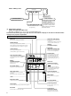
Model FDEN (P) series Heavy Duty RUN CHECK ON/OFF Remote controller signal receiver RUN LAMP (GREEN) BACK UP SWITCH When the remote controller is missing or defective, this switch can start and stop the air conditioner. Use the back up switch when the battery is exhausted, or when the remote controller is missing or defective. Usually operate the air conditioner with remote controller. Illuminates during operation. CHECK LAMP (YELLOW) When a malfunction occurs, the lamp flashing.
(3) Outline of microcomputer control function (a) Operation control function by the indoor controller 1) Automatic operation (Only heat pump type) If the Auto mode is selected on the remote control device, the selection of cooling or heating can be made automatically depending on the room temperature (and the temperature of indoor heat exchanger). (When the switching between the cooling and the heating is made within 3 minutes, the compressor will not operate for 3 minutes.
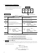
4) Dehumidifying operation (“THERMAL DRY”) The compressor, the indoor fan motor and the outdoor fan motor Operation block are operated intermittently under thermistor (ThI-A) control according to the appropriate operation block, to provide cooling operation for the dehumidifying. D C B -2 Low A +3 High Pattern of operation Set temp.
6) FM control with the heating thermostat turned off (For cold draft prevention) (Only heat pump type) In order to prevent a cold draft while the heating thermostat is turned off, the indoor blower is controlled in response to the temperature of the indoor heat exchanger as illustrated below. It should be noted that if SW3-4 on the indoor PCB is turned off, the indoor blower will stop so far as the temperature of the indoor heat exchanger is lower than 40˚C.
9) Condensate pump motor (DM) control (Only FDTN (P), FDT, FDR models) During the cooling or Dehumidifying operation, the condensate pump motor (DM) is synchronized with the start of compressor operation. If the operation is switched from the operation stop, error stop, thermostat stop and the cooling of defrosting operation to the fan or heating operation, the drain motor continues to operate for 2 minutes after the switching.
13) Compressor inching prevention control a) Compressor 3 minutes delay control The compressor will remain in stop state for three minutes. When the compressor is stopped by thermostat, ON/OFF switch, and/or by occurrence of trouble. When the power source is turned ON, the three-minute delay timer is cancelled. b) Compressor 3 minutes forced operation control Compressor cannot be stopped for 3 minutes after it started.
17) Drain detection a) (Only FDTN(P), FDT, FDR models) If there is detection of a drain abnormality during cooling operation, the drain pump goes ON for 5 minutes and the compressor which had been running comes to a stop. Overflow detection is carried out at all times with the float switch regardless of operational mode. If an overflow is generated (or if the float switch is not yet connected or has been disconnected).
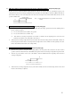
¡ At shipping from factory [FDTN (P), FDEN (P), FDKN (P) models : J3 (SW5-3), FDT, FDR, FDU, FDFL models : J5 (SW5-2) ] on PCB OFF] ¡ Input signal to CnT OFF → ON [Edge input] ... Air conditioner ON ¡ Input signal to CnT ON → OFF [Edge input] ... Air conditioner OFF ON CnT input ON OFF ON OFF OFF ON ON OFF Unit A ON OFF Remote controller operation OFF Remote controller operation ON (Last operation has priority.
¡ Keeping the louvers horizontal during heating (Only heat pump type) While HOT KEEP is displayed (during hot start operation or when the thermostat has turned off during heating operation), the louvers stay in the horizontal position to prevent cold drafts, independent of the setting of the AUTO SWING key (auto swing or stop). The louver position display of LCD displays continuously the original position before this control operation.
(b) Operation control function by the wired remote controller (i) The following is the sequence of operation for the remote controller operation mode switch. DRY (ii) COOL FAN HEAT AUTO CPU reset This functions when the " inspection " and " filter reset switch " on the remote controller are pushed simultaneously. It operates in the same manner as the power reset. (iii) Power outage compensation function. ¡ This is enabled by setting dip switch SW3 on the remote control circuit board to ON.
(c) Operation control function by the outdoor controller (Only FDC(P)208~508 type, FDC808, 1008 type) 1) Control for outdoor unit fan a) Cooling Operation The speed of the fan for the outdoor unit is controlled by the temperature of the heat exchanger (Tho-R detection) and the outdoor air temperature (Tho-A).
2) Control of fan for outdoor unit for de-icing If DIP switch SW5-2 on the printed circuit board for the outdoor unit is set to on, the Outdoor fan operates at Hi speed fan on the outdoor unit which has been stopped will operate for 10 seconds at Hi speed Outdoor fan stopped every 10 minutes when the outdoor air temperature is 3 °C or less.
5) Compressor protecting function (Microcomputer and phase protection relay) a) Overcurrent control (i) When a 52C secondary L1-phase continues for 0.5 seconds and when it is more than the set value (detection at current sensor CT), the compressor is stopped. The compressor is restarted after a 3-minute delay if the detection current is less than 1.5 to 2A. If this condition is re-detected 5 times within 60 minutes of the first occurrence, an abnormal stop of the unit is performed.
6) High-pressure protection by high-pressure make-or-break device (63H1) (Only case of FDCP208~508 and FDC808, 1008 type) a) If the pressure rises and 63H1 is operated (opened), the compressor is stopped. After a 3-minute delay, the compressor is restarted. An abnormal stop is performed when 63H1 is opened five times within 60 minutes of the first operation. e Restore after repairing.
8.5 APPLICATION DATA SAFETY PRECAUTIONS • Please read these “Safety Precautions” first then accurately execute the installation work. • Though the precautionary points indicated herein are divided under two headings. WARNING and CAUTION , those points which are related to the strong possibility of an installation done in error resulting in death or serious injury are listed in the WARNING section.
8.6 MAINTENANCE DATA 8.6.1 Servicing (1) Evacuation The evacuation is a procedure to purge impurities, such as noncondensable gas, air, moisture from the refrigerant equipment by using a vacuum pump. Since the refrigerant R22 and R407C is very insoluble in water, even a small amount of moisture left in the refrigerant equipment will freeze, causing what is called ice clogging. Evacuation procedure Make sure that the both service valves of gas and liquid line are fully opened.
(2) Refrigerant charging (a) After the evacuation shown in the above, change the connection of the charge hose A to the refrigerant cylinder. (b) Purge air from the charge hose A . First loosen the connecting portion of the charge hose at the gauge manifold side and open valve 3 for a few seconds, and then immediately retighten it after observing that gas has blown out from loosened connecting portion. (c) Open valves 1 and 3 then gas refrigerant begins flowing from the cylinder into the unit.
8.6.3 Diagnosing of microcomputer circuit (1) Selfdiagnosis function (a) Indoor unit side (i) Only case of wireless remote control model. Check indicator table Failure mode on the indoor unit indicated by flashing Yellow LED and Green LED.
(3) Error diagnosis procedures at the indoor unit side To diagnose the error, measure the voltage (AC, DC), resistance, etc. at each connector around the circuit board of indoor unit based on the inspection display or the operation state of unit (no operation of compressor or blower, no switching of 4-way valve, etc.). If any defective parts are discovered, replace with the assembly of parts as shown below. (a) Single-unit replacement parts for circuit board of indoor unit.
• Function of jumper wires Name J1(SW5-1) J2(SW5-2) J3(SW5-3) J4(SW4-1) J5(SW4-2) J6(SW4-3) J7(SW4-4) *1 J7(SW4-4) • Function of DIP switched (SW3) Function 1 Phase model 3 Phase model Cooling only type Heat pump type Pulse input Step input With None With None With None With None With None With None With None With None Switch ON OFF ON SW3-1 SW3-2 OFF ON OFF ON SW3-3 — Antifrost 2.
(c) Inspection method when there are fault lamps (display lamps on indoor unit).
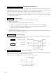
4 Abnormality casued by insufficient refrigerant. Are the characteristic values for the heat exchanger thermistor OK? Indoor unit Check Lamp (yellow) 5 time flashes NO Replace heat exchanger thermistor. YES Is the amount of refrigerant circulation good? (If refrigerant is insufficient, the capillary tubes may be plugged.) NO Charge with refrigerant. Replace capillary tubes. YES Note (1) Refer to previous page for heat exchanger thermistor temperature resistance characteristic values.
2 e6 Error display : [Defective indoor unit heat exchanger thermistor] Return air thermistor (ThI-A) Indoor unit heat exchanger thermistor (ThI-R) Resistance temperature characteristics Defective indoor unit PCB Replacement (Defective indoor unit heat exchanger thermistor input circuit) Resistance (kΩ) 15 YES Is the indoor unit heat exchanger thermistor connector connection OK? Are characteristics of indoor unit heat exchanger thermistor OK or is not there any broken wire? YES 10 5kΩ at 25˚C 5
5 e9 Error display : [Failure in drainage] Defective indoor unit PCB Replacement (Defective condensate motor output circuit) NO (1) YES Is there any overflow? Is the angle of drain piping good. Is there any problem? NO YES Is there output for condensate motor (DM)? Repair YES Is the float switch tripped? Repair or replace the float switch YES ¡Check DM broken wire, burning, locking. ¡Are there any DM connector loose. ¡Are there any PCB faston terminal loose. ¡Are there any DM wire broken.
(4) Outdoor unit side (FDC(P)208~508 type, FDC808, 1008 type) Check Indicator Table Failure mode on the outdoor unit is indicated by flashing both Green LED (LED-G) and Red LED (LED-R) on the printed circuit board. Outdoor unit LED Failure at: Green Red Keeps flashing Stays OFF Stays OFF 1 time flash Stays OFF Stays OFF Stays OFF Stays OFF Contents of the failure Normal/Power is supplied. Power wiring • The outdoor power wiring is in reversed phase. • Open phase at L3 phase (primary side).
PCB power supply connector Parts layout on the outdoor unit PCB (Primary side) 63H1 63H1 63H2 Inspection display lamp (LED·Red) 63H2 CNR PCB power supply connector 52C CF2 CF2 CF1 CF1 52C SV 20S SV SV2 X03 CNF (Secondary side) X02 X07 (LED·Green) SV2 X05 X08 CNA2 X09 LED-R LED-D Inspection display lamp 20S X01 F1 R3 R4 R1 R2 R5 R6 R7 R8 R11 R3 R12 R10 CNA1 X04 SW3 CNL SW4 OFF 2 (J4) OFF ON 1 (J17) OFF 2 (J18) OFF 3 (J19) OFF 4 (J20) OFF 27 ON ON
(b) Inspection method when there are fault lamps (outdoor unit LED) 1 Open phase at L3 phase (Primary side) Outdoor unit Red LED 1 time flash Green LED Stays OFF Is L3 phase at primary side at open phase YES Correction NO Defective outdoor unit PCB Replacement 2 Overcurrent of the compressor motor Outdoor unit Red LED 2 time flashes Green LED Stays OFF Power supply checked at L1 - L2 , L1 - L3 or L2 - L3 phase of 52C secondary side? NO YES (1) Compressor overcurrent? YES NO • 3 Phase: O
4 The outdoor heat exchanger temperature is too high (70°C or over) (1) Are the heat exchanger thermistor Charateristisc Normal? Outdoor unit Red LED 4 time flashes Green LED Stays OFF Check the unit side closely (1) YES Cooling, overload operation? NO Heart exchanger thermistor replacement • Is outdoor fan motor operating? • Is the outdoor unit shortcircuited? • Is the installation space adequate? • Is there too much refrigerant? Note (1) Outdoor unit heat exchanger thermistor detects the stat
7 Defective outdoor temperature thermistor Outdoor unit Red LED 2 time flashes 1 time flash Is the outdoor air temperature thermistor connector connection OK? YES Is the outdoor temperature thermistor characteristics OK, is there no broken wire? Defective outdoor unit PCB Replacement (Defective outdoor temperature thermistor input circuit) YES Temperature-resistance characteristics of outdoor temperature thermistor (ThO-A) NO NO Defective outdoor temperature thermistor Replacement <0] Thermistor
9 High pressure error [63H1] (Only case of FDCP208~508 type) Outdoor unit Red LED 4 time flashes Green LED 1 time flash YES Did 63H1 operate? At 63H1 opration • Is the outdoor unit fan motor operating? • Is there no shortcircuit in the outdoor unit? • Is sufficient space reserved for suction or discharge? • Is not the refrigerant charge excessive? NO Defective outdoor unit PCB Replacement (Defective 63H1, input circuit) 63H1, 49C operation (Only case of FDC808, 1008 type) Outdoor unit 4 time flashe
AIR CONDITIONING AND HEAT PUMP SYSTEMS NOTICE The installation of this equipment must comply with all NATIONAL, STATE and LOCAL CODES. This Service Guide does not cover all installation circumstances and is meant for guidance only and therefore will not form part of any legally binding contract. An installation guide is provided with the air conditioning equipment.