Manual No.
CONTENTS 1 GENERAL INFORMATION ................................................................................ 1 1.1 Specific features ......................................................................................... 1 1.2 How to read the model name ..................................................................... 1 2 SELECTION DATA ............................................................................................. 2 2.1 Specifications ............................................
5 APPLICATION DATA ....................................................................................... 70 5.1 Installation of indoor unit ......................................................................... 71 5.2 Installation of remote control ................................................................... 81 5.3 Installation of outdoor unit ....................................................................... 82 5.4 Electrical wiring ..................................................
1 GENERAL INFORMATION 1.1 Specific features (1) The long piping makes the location of the inside and units flexible.
2 SELECTION DATA 2.
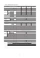
Models SKM28ZG-S, 35ZG-S, 50ZG-S, Model SKM28ZG-S SKM35ZG-S SKM50ZG-S Item Cooling capacity W 2800 3500 5000 Heating capacity W 4000 4500 5800 Sound level Hi : 38 Me : 31 Lo : 24 Hi : 39 Me : 32 Lo : 25 Hi : 45 Me : 36 Lo : 25 Cooling Power level Noise level Hi : 54 Hi : 55 Hi : 61 dB Sound level Hi : 40 Me : 34 Lo : 28 Hi : 41 Me : 35 Lo : 29 Hi : 44 Me : 39 Lo : 33 Heating Power level Noise level Exterior dimensions Hi : 58 Hi : 59 268 × 790 × 199 mm Height × Width
Models SKM60ZG-S, 71ZG-S Model SKM60ZG-S SKM71ZG-S Item Cooling capacity W 6000 7100 Heating capacity W 6800 8000 Sound level Hi : 43 Me : 36 Lo : 26 Hi : 44 Me : 34 Lo : 26 Cooling Power level Noise level Hi : 59 Hi : 60 dB Sound level Hi : 43 Me : 37 Power level Hi : 59 Lo : 27 Hi : 44 Me : 38 Lo : 27 Heating Noise level Exterior dimensions Hi : 60 318 × 1098 × 248 mm Height × Width × Depth Color Yellowish white Net weight kg 15 Air handling equipment Tangential fan ×
Models STM25ZF-S, 35ZF-S, 50ZF-S, 60ZF-S Models STM25ZF-S STM35ZF-S STM50ZF-S STM60ZF-S Item Cooling capacity W 2500 3500 5000 6000 Heating capacity W 3400 4500 5800 6800 35 38 40 47 51 54 56 63 Sound level 35 38 40 47 Power level 51 54 56 63 Sound level Cooling Power level dB Noise level Heating 248 × 570 × 570 Main unit Exterior dimensions mm Height × Width × Depth 35 × 700 × 700 Panel Color Plaster white (Panel) Main unit Net weight 14 14.5 kg Panel 3.
Models SRRM25ZF-S, 35ZF-S, 50ZF-S, 60ZF-S Models SRRM25ZF-S SRRM35ZF-S SRRM50ZF-S SRRM60ZF-S Item Cooling capacity W 2500 3500 5000 6000 Heating capacity W 3400 4500 5800 6800 38 40 46 49 53 55 60 63 Sound level 39 41 46 49 Power level 54 56 60 63 Sound level Cooling Power level dB Noise level Heating Exterior dimensions 230 × 740 × 455 mm Height × Width × Depth Color — Net weight kg 22.0 23.
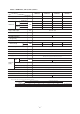
(2) Outdoor unit Models SCM40ZG-S, 45ZG-S Models SCM40ZG-S SCM45ZG-S Item Cooling capacity W 4000 (1900 ~ 5000) 4500 (1000 ~ 6400) Heating capacity W 5000 (2200 ~ 5200) 5600 (1800 ~ 6800) Power source 1 Phase 220/230/240V 50Hz Cooling 970 (470 ~ 1430) 1190 (190 ~ 2220) Heating 1150 (400 ~ 1410) 1350 (220 ~ 1940) Cooling 4.5/4.3/4.1 5.5/5.2/5.0 5.3/5.1/4.8 6.2/5.9/5.
Models SCM48ZG-S SCM60ZG-S Item Cooling capacity W 4800 (1100~6900) 6000 (1100~7500) Heating capacity W 6000 (1400~7100) 7000 (1400~7600) Power source 1 Phase 220/230/240V 50Hz Cooling Power consumption 1190 (200~2350) 1620 (400~3050) 1380 (180~2030) 1740 (390~2620) 5.5/5.2/5.0 7.4/7.1/6.8 W Heating Cooling Running current A Heating 6.3/6.1/5.8 Sound level Noise level 8.0/7.6/7.
Model SCM80ZG-S Model SCM80ZG-S Item Cooling capacity W Heating capacity W 8000 (1800~9500) 9300 (800~9600) Power source 1 Phase 220/230/240V 50Hz Cooling Power consumption 2220 (310~3000) W Heating 2430 (210~3430) Cooling Running current 10.2/9.7/9.3 A Heating 11.2/10.7/10.
(3) Operation data ¡ The combinations of the indoor units is indicated by numbers. They are read as follows. (Example) SKM22ZG-S / 22 SKM35ZG-S / 35 ¡ The capacity of the indoor units is shown by rooms. If this exceeds the maximum capacity of the outdoor unit, the demand capacity will be proportionally distributed. ¡ If units are to be combined, use the table below to make the proper selection.
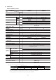
Model SCM45ZG-S (a) Heating Indoor unit combination 1 room 2 room 20 22 25 28 35 20 + 20 20 + 22 20 + 25 20 + 28 20 + 35 22 + 22 22 + 25 22 + 28 22 + 35 25 + 25 25 + 28 25 + 35 28 + 28 28 + 35 35 + 35 Heating capacity (kW) Room heating capacity (kW) Total capacity (kW) Standard Max. A room B room Min. 4.2 3.0 3.0 1.8 4.4 3.2 3.2 1.8 4.7 3.4 3.4 1.8 4.8 4.0 4.0 1.8 4.8 4.5 4.5 1.8 6.8 5.4 2.70 2.70 2.6 6.8 5.5 2.62 2.88 2.6 6.8 5.6 2.49 3.11 2.6 6.8 5.8 2.42 3.38 2.6 6.8 6.0 2.18 3.82 2.6 6.8 5.6 2.
Model SCM48ZG-S (a) Heating Indoor unit combination 1 room 2 room 3 room 20 22 25 28 35 20 + 20 20 + 22 20 + 25 20 + 28 20 + 35 22 + 22 22 + 25 22 + 28 22 + 35 25 + 25 25 + 28 25 + 35 28 + 28 28 + 35 35 + 35 20 + 20 + 20 20 + 20 + 22 20 + 20 + 25 20 + 20 + 28 20 + 20 + 35 20 + 22 + 22 20 + 22 + 25 20 + 22 + 28 20 + 22 + 35 20 + 25 + 25 20 + 25 + 28 20 + 25 + 35 20 + 28 + 28 20 + 28 + 35 22 + 22 + 22 22 + 22 + 25 22 + 22 + 28 22 + 22 + 35 22 + 25 + 25 22 + 25 + 28 22 + 25 + 35 22 + 28 + 28 22 + 28 + 35
Model SCM48ZG-S (b) Cooling Indoor unit combination 1 room 2 room 3 room 20 22 25 28 35 20 + 20 20 + 22 20 + 25 20 + 28 20 + 35 22 + 22 22 + 25 22 + 28 22 + 35 25 + 25 25 + 28 25 + 35 28 + 28 28 + 35 35 + 35 20 + 20 + 20 20 + 20 + 22 20 + 20 + 25 20 + 20 + 28 20 + 20 + 35 20 + 22 + 22 20 + 22 + 25 20 + 22 + 28 20 + 22 + 35 20 + 25 + 25 20 + 25 + 28 20 + 25 + 35 20 + 28 + 28 20 + 28 + 35 22 + 22 + 22 22 + 22 + 25 22 + 22 + 28 22 + 22 + 35 22 + 25 + 25 22 + 25 + 28 22 + 25 + 35 22 + 28 + 28 22 + 28 + 35 2
Model SCM60ZG-S (a) Heating Indoor unit combination 1 room 2 room 3 room 20 22 25 28 35 50 60 20 + 20 20 + 22 20 + 25 20 + 28 20 + 35 20 + 50 20 + 60 22 + 22 22 + 25 22 + 28 22 + 35 22 + 50 22 + 60 25 + 25 25 + 28 25 + 35 25 + 50 25 + 60 28 + 28 28 + 35 28 + 50 28 + 60 35 + 35 35 + 50 35 + 60 50 + 50 50 + 60 20 + 20 + 20 20 + 20 + 22 20 + 20 + 25 20 + 20 + 28 20 + 20 + 35 20 + 20 + 50 20 + 20 + 60 20 + 22 + 22 20 + 22 + 25 20 + 22 + 28 20 + 22 + 35 20 + 22 + 50 20 + 22 + 60 20 + 25 + 25 20 + 25 + 28 2
Model SCM60ZG-S (a) Heating Indoor unit combination 3 room 25 + 28 + 28 25 + 28 + 35 25 + 28 + 50 25 + 35 + 35 25 + 35 + 50 28 + 28 + 28 28 + 28 + 35 28 + 28 + 50 28 + 35 + 35 35 + 35 + 35 Heating capacity (kW) Room heating capacity (kW) Total capacity (kW) Standard Max. A room B room C room Min. 7.6 7.0 2.8 2.42 2.42 2.16 7.6 7.0 2.8 2.78 2.23 1.99 7.6 7.2 3.0 3.50 1.96 1.75 7.6 7.1 2.8 2.62 2.62 1.87 7.6 7.3 3.0 3.32 2.32 1.66 7.6 7.0 2.8 2.33 2.33 2.33 7.6 7.1 2.8 2.73 2.18 2.18 7.6 7.3 3.0 3.44 1.
Model SCM60ZG-S (b) Cooling Indoor unit combination 1 room 2 room 3 room 20 22 25 28 35 50 60 20 + 20 20 + 22 20 + 25 20 + 28 20 + 35 20 + 50 20 + 60 22 + 22 22 + 25 22 + 28 22 + 35 22 + 50 22 + 60 25 + 25 25 + 28 25 + 35 25 + 50 25 + 60 28 + 28 28 + 35 28 + 50 28 + 60 35 + 35 35 + 50 35 + 60 50 + 50 50 + 60 20 + 20 + 20 20 + 20 + 22 20 + 20 + 25 20 + 20 + 28 20 + 20 + 35 20 + 20 + 50 20 + 20 + 60 20 + 22 + 22 20 + 22 + 25 20 + 22 + 28 20 + 22 + 35 20 + 22 + 50 20 + 22 + 60 20 + 25 + 25 20 + 25 + 28 20
Model SCM60ZG-S (b) Cooling Indoor unit combination 3 room 25 + 28 + 28 25 + 28 + 35 25 + 28 + 50 25 + 35 + 35 25 + 35 + 50 28 + 28 + 28 28 + 28 + 35 28 + 28 + 50 28 + 35 + 35 35 + 35 + 35 Cooling capacity (kW) Room cooling capacity (kW) Total capacity (kW) A room B room C room Min. Standard Max. 7.5 5.9 3.3 2.04 2.04 1.82 7.5 6.1 3.3 2.43 1.94 1.73 7.5 6.5 3.5 3.16 1.77 1.58 7.5 6.3 3.3 2.32 2.32 1.66 7.5 6.7 3.5 3.05 2.13 1.52 7.5 6.0 3.3 2.00 2.00 2.00 7.5 6.2 3.3 2.38 1.91 1.91 7.5 6.6 3.5 3.11 1.
Model SCM80ZG-S (a) Heating Indoor unit combination 1 room 2 room 3 room 20 22 25 28 35 50 60 71 20 + 20 20 + 22 20 + 25 20 + 28 20 + 35 20 + 50 20 + 60 20 + 71 22 + 22 22 + 25 22 + 28 22 + 35 22 + 50 22 + 60 22 + 71 25 + 25 25 + 28 25 + 35 25 + 50 25 + 60 25 + 71 28 + 28 28 + 35 28 + 50 28 + 60 28 + 71 35 + 35 35 + 50 35 + 60 35 + 71 50 + 50 50 + 60 60 + 60 60 + 71 20 + 20 + 20 20 + 20 + 22 20 + 20 + 25 20 + 20 + 28 20 + 20 + 35 20 + 20 + 50 20 + 20 + 60 20 + 20 + 71 20 + 22 + 22 20 + 22 + 25 20 + 22
Model SCM80ZG-S (a) Heating Indoor unit combination 22 + 22 + 71 22 + 25 + 25 22 + 25 + 28 22 + 25 + 35 22 + 25 + 50 22 + 25 + 60 22 + 25 + 71 22 + 28 + 28 22 + 28 + 35 22 + 28 + 50 22 + 28 + 60 22 + 28 + 71 22 + 35 + 35 22 + 35 + 50 22 + 35 + 60 22 + 35 + 71 22 + 50 + 50 22 + 50 + 60 25 + 25 + 25 25 + 25 + 28 25 + 25 + 35 25 + 25 + 50 25 + 25 + 60 25 + 25 + 71 3 25 + 28 + 28 room 25 + 28 + 35 25 + 28 + 50 25 + 28 + 60 25 + 28 + 71 25 + 35 + 35 25 + 35 + 50 25 + 35 + 60 25 + 35 + 71 25 + 50 + 50 25 + 50 +
Model SCM80ZG-S (a) Heating Indoor unit combination 20 + 22 + 22 + 50 20 + 22 + 22 + 60 20 + 22 + 22 + 71 20 + 22 + 25 + 25 20 + 22 + 25 + 28 20 + 22 + 25 + 35 20 + 22 + 25 + 50 20 + 22 + 25 + 60 20 + 22 + 28 + 28 20 + 22 + 28 + 35 20 + 22 + 28 + 50 20 + 22 + 28 + 60 20 + 22 + 35 + 35 20 + 22 + 35 + 50 20 + 25 + 25 + 25 20 + 25 + 25 + 28 20 + 25 + 25 + 35 20 + 25 + 25 + 50 20 + 25 + 25 + 60 20 + 25 + 28 + 28 20 + 25 + 28 + 35 20 + 25 + 28 + 50 20 + 25 + 28 + 60 20 + 25 + 35 + 35 20 + 25 + 35 + 50 20 + 28
Model SCM80ZG-S (a) Heating Indoor unit combination 28 + 28 + 28 + 28 28 + 28 + 28 + 35 4 28 + 28 + 28 + 50 room 28 + 28 + 35 + 35 28 + 35 + 35 + 35 Heating capacity (kW) Room heating capacity (kW) Total capacity (kW) A room B room C room D room Max. Min. Standard 9.6 9.2 3.6 2.30 2.30 2.30 2.30 9.6 9.2 3.6 2.71 2.16 2.16 2.16 9.6 9.3 3.7 3.47 1.94 1.94 1.94 9.6 9.3 3.6 2.58 2.58 2.07 2.07 9.6 9.3 3.6 2.45 2.45 2.45 1.96 - 21 - Power consumption (W) Standard current (A) Min. Standard Max.
Model SCM80ZG-S (b) Cooling Indoor unit combination 1 room 2 room 3 room 20 22 25 28 35 50 60 71 20 + 20 20 + 22 20 + 25 20 + 28 20 + 35 20 + 50 20 + 60 20 + 71 22 + 22 22 + 25 22 + 28 22 + 35 22 + 50 22 + 60 22 + 71 25 + 25 25 + 28 25 + 35 25 + 50 25 + 60 25 + 71 28 + 28 28 + 35 28 + 50 28 + 60 28 + 71 35 + 35 35 + 50 35 + 60 35 + 71 50 + 50 50 + 60 60 + 60 60 + 71 20 + 20 + 20 20 + 20 + 22 20 + 20 + 25 20 + 20 + 28 20 + 20 + 35 20 + 20 + 50 20 + 20 + 60 20 + 20 + 71 20 + 22 + 22 20 + 22 + 25 20 + 22 +
Model SCM80ZG-S (b) Cooling Indoor unit combination 22 + 22 + 71 22 + 25 + 25 22 + 25 + 28 22 + 25 + 35 22 + 25 + 50 22 + 25 + 60 22 + 25 + 71 22 + 28 + 28 22 + 28 + 35 22 + 28 + 50 22 + 28 + 60 22 + 28 + 71 22 + 35 + 35 22 + 35 + 50 22 + 35 + 60 22 + 35 + 71 22 + 50 + 50 22 + 50 + 60 25 + 25 + 25 25 + 25 + 28 25 + 25 + 35 25 + 25 + 50 25 + 25 + 60 25 + 25 + 71 3 25 + 28 + 28 room 25 + 28 + 35 25 + 28 + 50 25 + 28 + 60 25 + 28 + 71 25 + 35 + 35 25 + 35 + 50 25 + 35 + 60 25 + 35 + 71 25 + 50 + 50 25 + 50 + 6
Model SCM80ZG-S (b) Cooling Indoor unit combination 20 + 22 + 22 + 50 20 + 22 + 22 + 60 20 + 22 + 22 + 71 20 + 22 + 25 + 25 20 + 22 + 25 + 28 20 + 22 + 25 + 35 20 + 22 + 25 + 50 20 + 22 + 25 + 60 20 + 22 + 28 + 28 20 + 22 + 28 + 35 20 + 22 + 28 + 50 20 + 22 + 28 + 60 20 + 22 + 35 + 35 20 + 22 + 35 + 50 20 + 25 + 25 + 25 20 + 25 + 25 + 28 20 + 25 + 25 + 35 20 + 25 + 25 + 50 20 + 25 + 25 + 60 20 + 25 + 28 + 28 20 + 25 + 28 + 35 20 + 25 + 28 + 50 20 + 25 + 28 + 60 20 + 25 + 35 + 35 20 + 25 + 35 + 50 20 + 28 +
Model SCM80ZG-S (b) Cooling Indoor unit combination 28 + 28 + 28 + 28 28 + 28 + 28 + 35 4 28 + 28 + 28 + 50 room 28 + 28 + 35 + 35 28 + 35 + 35 + 35 Cooling capacity (kW) Room cooling capacity (kW) Total capacity (kW) A room B room C room D room Max. Min. Standard 1.98 9.5 1.98 7.9 1.98 1.98 3.8 2.32 9.5 1.86 7.9 1.86 1.86 3.8 2.99 9.5 1.67 8.0 1.67 1.67 4.1 2.22 9.5 2.22 8.0 1.78 1.78 3.8 2.11 9.5 2.11 8.0 1.68 2.11 3.8 - 25 - Power consumption (W) Standard current (A) Min. Standard Max.
2.2 Range of usage & limitations Models SCM40ZG-S SCM45ZG-S SCM48ZG-S SCM60ZG-S SCM80ZG-S Item Indoor intake air temperature (Upper, lower limits) Cooling 18 to 32°C Heating 15 to 30°C Outdoor air temperature (Upper, lower limits) Cooling -15 to 43°C Heating -15 to 24°C Indoor units that can be used in combination Number of connected units Total of indoor Units (class kW) Total length for all rooms 1 to 2 units 5.7kW 2 to 3 units 7.0kW 8.5kW Max. 30m Power source voltage 13.5kW Max.
2.3 Exterior dimensions (1) Indoor unit Models SKM20ZG-S, 22ZG-S, 25ZG-S, 28ZG-S, 35ZG-S, 50ZG-S Unit : mm A → 790 199 3 9 60 268 Piping hole right(left) 138 450 206.5 450 102.5 Terminal block 45 133.5 102.5 585 7.5 43.2 39.3 202 Pipng for Gas 53.5 ø9.52 ( 20 ~ 5035 :: ø12.7 ) 53.5 27 45 60 45 252.2 60 8.3 44.5 44.5 200 788 17.5 380.6 Pipng for Liquid 448.6 (ø6.
Models STM25ZF-S, 35ZF-S, 50ZF-S, 60ZF-S Celling opening 660 (For conventional celling) Hanging bolt pitch 530 68 541 Hanging bolt pitch 530 350 319 PANEL 202 Air intake 413 700 Air outlet Control box 43 Drain hose (accessory) To be installed at site B D Mark 570 243 104 Description Model E A 35 45 or more 197 137 93 196 250 C 25,35ZF-S 50,60ZF-S A Gas pipe connecting port ø 9.52(Flare) ø 12.7(Flare) B Liquid pipe connecting port ø 6.
(2) Outdoor unit Models SCM40ZG-S, 45ZG-S, 48ZG-S, 60ZG-S Drain holes 286.4 Unit : mm 50 12 328 14 49.6 314 290 43.5 12 476 203.1 510 Elogated hole (2-12X16) 136.9 Terminal block 124 Liquid line service valve C Unit (ø6.35) (48, 60 type only) 34.6 Gas line service valve B Unit (ø9.52) Liquid line service valve A Unit (ø6.35) 20º 42.7 67.9 20º 100.3 Gas line service valve C Unit (ø9.52) (48, 60 type only) Liquid line service valve B Unit (ø6.35) 42.7 67.9 640 42.
2.4 (ø9.52) (ø9.52) Indoor unit 4 way valve Check joint Muffler - Sensor (ThO-D) Discharge 30 - Sensor (ThI-R2) Heat exchanger Sensor (ThO-C) Suction Sensor (ThI-R1) Accumlator Compressor Sensor (ThO-R) Strainer Heat exchanger Sensor (ThI-A) Liquid line (ø6.35) (ø6.
Gas line (ø9.52) Sensor (ThO-A) Service valve (Gas) (ø9.52) Indoor unit 4 way valve Check joint Muffler - Sensor (ThO-D) 31 - Sensor (ThI-R2) Discharge Sensor (ThI-R1) Suction Sensor (ThO-C) Heat exchanger Compressor Strainer Heat exchanger Sensor (ThI-A) Liquid line (ø6.35) (ø6.
Gas line Service valve (Gas) (ø9.52 ) Sensor (ThO-A) (ø9.52 ) (ø9.52 ) Sensor (ThI-R2) 4way valve Indoor Unit Oil separator Heat exchanger Heat exchanger - 32 - Sensor (ThO-D) Discharge Sensor (ThO-R) Suction Compressor Sensor (ThI-R1) Sensor (ThI-A) Service valve (Liquid) (ø6.35) Sensor (Tho-C) Electronic expansion valve EEVA Strainer Liquid line (ø6.35) EEVB (ø6.
Gas line Service valve (Gas) (ø9.52 or ø12.7) Sensor (ThO-A) (ø9.52 or ø12.7) (ø9.52 or ø12.7) Sensor (ThI-R2) 4way valve Indoor Unit Heat exchanger Heat exchanger - Sensor (ThO-D) Muffler 33 - Discharge Sensor (ThO-R) Sensor (Tho-C) Compressor Sensor (ThI-R1) Sensor (ThI-A) Suction Service valve (Liquid) (ø6.35) Accumlator Electronic expansion valve EEVA Receiver Strainer (ø6.35) EEVB (ø6.35) EEVC Liquid line Capillary tube Gas line 20, 22, 25, 28, 35 type : ø9.
Cooling cycle Heating cycle Outdoor Unit (ø9.52 or ø12.7) Service valve (Gas) Heat exchanger (ø9.52 or ø12.7) Sensor (ThO-A) (ø9.52 or ø12.7) Sensor (ThI-R2) 4way valve (ø9.52 or ø12.7) Indoor Unit Oil separator Heat exchanger Sensor (ThO-C) Sensor (ThO-D) Capillary tube - Discharge 34 - Compressor Sensor (ThI-R1) Suction Accumlator Electronic Service valve expansion valve (Liquid) EEVA (ø6.35) Strainer Sensor (ThI-A) EEVB (ø6.35) EEVC (ø6.35) EEVD Liquid line (ø6.
2.5 Selection chart Correct the cooling and heating capacity in accordance with the conditions as follows. The net cooling and heating capacity can be obtained in the following way. Net capacity = Capacity shown on specification × Correction factors as follows. (1) Coefficient of cooling and heating capacity in relation to temperatures MUL 1.3 1.2 Cooling Coefficient of cooling & Heating capacity in relation to temperature 1.1 1.0 Heating 0.9 0.8 0.7 0.6 43 ˚CD. B. Cooling operation Outdoor air D.
3 ELECTRICAL DATA Meaning of marks • Outdoor Unit Symbol CM FMO L EEVA ~ D 20S Parts name Compressor motor Fan motor Reactor Electronic expansion valve 4 way valve (coil) Symbol Tho-A Tho-R Tho-D Tho-C Parts name Sensor (outdoor air temp.) Sensor (outdoor H.X temp.) Sensor (discharge pipe temp.) Sensor (suction pipe temp.) Parts name Fan motor Flap motor Louver motor Varistor Fuse Drain motor Symbol FS Tr ThI-A ThI-R1 ThI-R2 Parts name Float switch Transformer Sensor (room temp.) Sensor (indoor H.
Models SKM60ZG-S, 71ZG-S TB Y/G HEAT EXCHANGER RD BK RD EXTERNAL CONTROL KIT RD FMI BK Y/G WH 6 5 4 CNU 3 1 BK YL WH WH BL S/N R/L G J F ZNR 250V 3.
Models STM25ZF-S, 35ZF-S, 50ZF-S, 60ZF-S SM FMI RD BK WH YL BL Control box 1 3 4 5 6 CNM YL DM CNU RD WH CNB BK CNQ S/N WH ZNR R/L BK F (250V 3.
N EARTH T2 1 2 3 UNIT A - T3 39 - UNIT B 1 2 3 Y/G Y/G AC.N GR BL AC.L PWB2 (POWER) BL AC.N N-1 G3 BK WH RD CNO BK WH BR CNP P_1 N_1 P_1 PWB3 (CAPACITOR) CNG N_1 CNG CNH G2 Color symbol Black BK Blue BL Brown BR Gray GR Orange OR Red RD White WH Y/G Yellow/Green CNB 20S FMo U RD V WH W BK RD WH BK CNG CNH BK PWB1 (MAIN) LED E ERROR (Red) CNT OR OR RD DC-P DC-N Y/G OR OR AF_L2 AF_L1 BK WH AC.
Model SCM48ZG-S Power Source 1 Phase 220-240V 50Hz WH N EARTH T2 Y/G Y/G L-1 N-1 BL BL - 40 - BK WH RD CNO PWB2 (POWER) AC.N UNIT B 1 2 3 BK WH BR CNP UNIT C 1 2 3 BK WH BL CNR P_1 PWB3 (CAPACITOR) CNG N_1 OR OR U RD V WH W BK RD WH BK CNG CNH CNG CNH RD BK DC-P DC-N G2 OR OR AF_L2 AF_L1 AC.L P_1 N_1 1 2 3 Color symbol Black BK Blue BL Brown BR Gray GR Orange OR Red RD White WH Y/G Yellow/Green AC.N GR G3 UNIT A Y/G AC.
Model SCM60ZG-S Power Source 1 Phase 220-240V 50Hz WH N EARTH T2 Y/G Y/G L-1 N-1 AC.L AC.N BL BL AC.N - 41 - UNIT A CNO UNIT B 1 2 3 BK WH BR CNP UNIT C 1 2 3 BK WH BL CNR P_1 PWB3 (CAPACITOR) CNG N_1 OR OR U RD V WH W BK RD WH BK CNG CNH CNG CNH RD BK DC-P DC-N G2 OR OR AF_L2 AF_L1 PWB2 (POWER) P_1 N_1 BK WH RD Color symbol Black BK Blue BL Brown BR Gray GR Orange OR Red RD White WH Y/G Yellow/Green GR G3 1 2 3 Y/G AC.
T2 UNIT A T3 UNIT B - 42 - T4 UNIT C T5 UNIT D 1 2 3 EARTH 1 2 3 EARTH 1 2 3 EARTH 1 2 3 EARTH BK WH RD Y/G BK WH BR Y/G BK WH BL Y/G BK WH YL L-1 N-1 G3 AC.L AC.N GR GR BL BL AC.L PWB2 (POWER) AC.
4 OUTLINE OF OPERATION CONTROL BY MICROCOMPUTER 4.1 Operation control function by remote control switch Remote control SKM model S Operation section FAN SPEED button OPERATION MODE select button Each time the button is pushed, the indicator is switched over in turn. Each time the button pushed, the indicator is switched over in turn. ON/OFF (luminous) button HI POWER/ECONO button Press for starting operation, press again for stopping. This button changes the HIGH POWER/ ECONOMY mode.
STM, SRRM model S Operation section FAN SPEED button Each time the button is pushed, the cator is switched over in turn. OPERATION MODE select button indi- Each time the button is pushed, the cator is switched over in turn. indi- ON/OFF button HI POWER button Press for starting operation, press again for stopping. This button changes the HIGH POWER mode. ECONO button AIR FLOW button This button changes the ECONOMY mode. This button changes the flap mode.
Unit indlcation section S SKM20~50 model TIMER light (yellow) HI POWER light (green) Illuminates during TIMER operation. Illuminates during HIGH POWER operation. RUN (HOT KEEP) light (green) 3D AUTO light (green) • Illuminates during operation. • Blinks at air flow stop due to the ‘HOT KEEP’ and ‘CLEAN operation’. 1.5 sec. ON HOT KEEP OFF 0.5 sec. 3 sec. Illuminates during 3D AUTO operation. RUN TIMER ON / OFF HI POWER 3D AUTO ON CLEAN operation OFF 1 sec.
4.2 Unit ON/OFF button When the remote control batteries become weak, or if the remote control is lost or malfunctioning, this button may be used to turn the unit on and off. (1) Operation Push the button once to place the unit in the automatic mode. Push it once more to turn the unit off. (2) Details of operation The unit will go into the automatic mode in which it automatically determines, from room temperature (as detected by sensor), whether to go into the cooling, thermal dry or heating modes.
4.3 Drain motor forced operation functions (STM, SRRM only) (1) Operation • When the float switch detects drain water, please use the wireless remote control to set the operation mode to "heating", set the temperature to 30°C, and set the timer to continuous operation. • When the float switch detects drain water, press the TEST switch on wired remote control for 3 seconds. (2) Detail of operation Sets the decision speed to 0 rps, stops the indoor fan motor, and only lets the drain motor run for 5 minutes.
4.5 Custom cord switching procedure If two wireless remote controls are installed in one room, in order to prevent wrong operation due to mixed signals, please modify the printed circuit board in the indoor unit’s control box and the remote control using the following procedure. Be sure to modify both boards. If only one board is modified, receiving (and operation) cannot be done.
4.7 Flap and louver control (SKM, STM only) S SKM model Control the flap and louver by AIRFLOW (UP/DOWN) and (LEFT/RIGHT) button on the wireless remote control. (1) Flap Each time when you press the AIRFLOW (UP/DOWN) button the mode changes as follows. (Flap stopped) (Swing) • Angle of Flap from Horizontal Remote control display COOL , DRY Approx. 10˚ Approx. 20˚ Approx. 30˚ Approx. 45˚ Approx. 60˚ HEAT Approx. 20˚ Approx. 35˚ Approx. 50˚ Approx. 60˚ Approx.
S STM model Control the flap by AIRFLOW button on the wireless remote control. (1) Air scroll The flap will be automatically set to the angle of air flow best to operation. During cooling and s dry operation t During heating s operation t Stops at this position for 5 seconds. Stops at this position for 5 seconds. Thick line : moves quickly Thick line : moves quickly Thin line : moves slowly Thin line : moves slowly (2) Swing flap Flap moves in upward and downward directions continuously.
4.8 3D auto operation (SKM only) Control the flap and louver by 3D AUTO button on the wireless remote control. Air flow selection and air flow direction are automatically controlled, allowing the entire room to efficiently conditioned. (1) During Cooling and Heating (Including auto cooling and heating) (a) Air flow selection is determined according to room temperature and setting temperature. Operation mode At cooling At heating Air flow selection AUTO Room temp. – Setting temp. >5˚C Room temp.
4.9 Timer operation (1) Comfortable timer setting (ON timer) If the timer is set at ON when the operation select switch is set at the cooling or heating, or the cooling or heating in auto mode operation is selected, the comfortable timer starts and determines the starting time of next operation based on the initial value of 15 minutes and the relationship between the room temperature at the setting time (temperature of room temperature sensor) and the setting temperature.
4.11 Outline of heating operation (1) Summary (a) Capacity control Model SCM40ZG-S SCM45ZG-S SCM48ZG-S SCM60ZG-S SCM80ZG-S Capacity 2.2 ~ 5.2 kW 1.8 ~ 6.8 kW 1.4 ~ 7.1 kW 1.4 ~ 7.6 kW 0.8 ~ 9.6 kW Capacity control is within the range shown above. If demand capacity of the indoor units exceeds the maximum capacity of the outdoor unit, the demand capacity will be proportionally distributed.
(b) SCM60ZG-S ◆SKM model (rps) Model SKM20ZG-S SKM22ZG-S SKM25ZG-S SKM28ZG-S SKM35ZG-S AUTO 7 ~ 47 7 ~ 50 7 ~ 55 7 ~ 58 7 ~ 65 HI 7 ~ 47 7 ~ 50 7 ~ 55 7 ~ 58 7 ~ 65 MED 7 ~ 34 7 ~ 38 7 ~ 41 7 ~ 45 7 ~ 49 7 ~ 33 Fan speed LO 7 ~ 23 7 ~ 26 7 ~ 28 7 ~ 31 HI POWER 46 54 58 65 65 ECONO 7 ~ 34 7 ~ 38 7 ~ 41 7 ~ 45 7 ~ 49 (rps) Model SKM50ZG-S SKM60ZG-S AUTO 9 ~ 71 12 ~ 88 HI 9 ~ 71 12 ~ 88 MED 9 ~ 55 12 ~ 64 LO 9 ~ 38 12 ~ 42 Fan speed HI POWER 81 88 EC
(c) SCM80ZG-S ◆SKM model (rps) Model SKM20ZG-S SKM22ZG-S SKM25ZG-S SKM28ZG-S SKM35ZG-S AUTO 7 ~ 47 7 ~ 50 7 ~ 55 7 ~ 58 7 ~ 65 HI 7 ~ 47 7 ~ 50 7 ~ 55 7 ~ 58 7 ~ 65 MED 7 ~ 34 7 ~ 38 7 ~ 41 7 ~ 45 7 ~ 49 7 ~ 33 Fan speed LO 7 ~ 23 7 ~ 26 7 ~ 28 7 ~ 31 HI POWER 46 54 58 65 65 ECONO 7 ~ 34 7 ~ 38 7 ~ 41 7 ~ 45 7 ~ 49 (rps) Model SKM50ZG-S SKM60ZG-S SKM71ZG-S AUTO 9 ~ 75 12 ~ 88 12 ~ 95 HI 9 ~ 75 12 ~ 88 12 ~ 95 MED 9 ~ 58 12 ~ 64 12 ~ 70 LO 9 ~ 40 12
(5) Defrosting (a) When the following conditions are met, the defrosting operation will start. 1) During normal operation a) When 40 minutes has passed since the start of heating or 40 minutes after the last defrosting (based on cumulative operation time of compressor). b) When the outdoor heat exchanger sensor (Tho-R) temperature is –2 °C or less for 3 continuous minutes after 37 minutes have passed. c) Outdoor temperature sensor (Tho-A) – outdoor heat exchanger sensor (Tho-R) temperature > = 0.
4.12 Outline of cooling operation (1) Summary (a) Capacity control Model SCM40ZG-S SCM45ZG-S SCM48ZG-S SCM60ZG-S SCM80ZG-S Capacity 1.9 ~ 5.0 kW 1.0 ~ 6.4 kW 1.1 ~ 6.9 kW 1.1 ~ 7.5 kW 1.8 ~ 9.5 kW Capacity control is within the range shown above. If demand capacity of the indoor units exceeds the maximum capacity of the outdoor unit, the demand capacity will be proportionally distributed.
(b) SCM60ZG-S ◆ SKM model (rps) Model SKM20ZG-S SKM22ZG-S SKM25ZG-S SKM28ZG-S SKM35ZG-S AUTO 7 ~ 27 7 ~ 31 7 ~ 33 7 ~ 37 7 ~ 48 HI 7 ~ 27 7 ~ 31 7 ~ 33 7 ~ 37 7 ~ 48 MED 7 ~ 21 7 ~ 24 7 ~ 27 7 ~ 30 7 ~ 37 LO 7 ~ 16 7 ~ 17 7 ~ 19 7 ~ 22 7 ~ 26 HI POWER 27 28 31 35 43 ECONO 7 ~ 21 7 ~ 24 7 ~ 27 7 ~ 30 7 ~ 37 Fan speed (rps) Model SKM50ZG-S SKM60ZG-S AUTO 9 ~ 62 12 ~ 84 HI 9 ~ 62 12 ~ 84 MED 9 ~ 40 12 ~ 60 LO 9 ~ 26 12 ~ 38 Fan speed HI POWER 58 84
(c) SCM80ZG-S ◆ SKM model (rps) Model SKM20ZG-S SKM22ZG-S SKM25ZG-S SKM28ZG-S SKM35ZG-S AUTO 7 ~ 27 7 ~ 31 7 ~ 33 7 ~ 37 7 ~ 48 HI 7 ~ 27 7 ~ 31 7 ~ 33 7 ~ 37 7 ~ 48 MED 7 ~ 21 7 ~ 24 7 ~ 27 7 ~ 30 7 ~ 37 LO 7 ~ 16 7 ~ 17 7 ~ 19 7 ~ 22 7 ~ 26 HI POWER 27 28 31 35 43 ECONO 7 ~ 21 7 ~ 24 7 ~ 27 7 ~ 30 7 ~ 37 Fan speed (rps) Model SKM50ZG-S SKM60ZG-S SKM71ZG-S AUTO 9 ~ 65 12 ~ 84 12 ~ 95 HI 9 ~ 65 12 ~ 84 12 ~ 95 MED 9 ~ 42 12 ~ 60 12 ~ 68 LO 9 ~ 28
4.13 Outline of automatic operation (1) Determination of operation mode The unit checks the room temperature and the outdoor air temperature after operating the indoor and outdoor blowers for 20 seconds, determines the operation mode and the room temperature setting correction value, and then enters in the automatic operation. Cooling 27.5 25.5 Room temperature (°C) Dehumidifying 19.
4.14 Operation permission/prohibition control The air conditioner operation is controlled by releasing the jumper wire (J3) on the indoor control board and inputting the external signal into the CnT. Note (1) Please install the separately-sold Interface kit (SC-BIK-E) for SKM models 20 - 50. Remove the jumper wire (J1 or J3) from the Interface kit circuit board. (Refer to "7.
4.15 External control (remote display)/control of input signal (1) External control (remote display) output Following output connectors (CNT) are provided on the printed circuit board of indoor unit. Note (1) Please install the separately-sold Interface kit (SC-BIK-E) for SKM models 20 - 50. The output connector (CNT) is located on the circuit board of the Interface kit. (Refer to "7.1 Interface kit") • Operation output: Power to engage DC 12V relay (provided by the customer) is outputted during operation.
4.16 Protective control function (1) Frost prevention for indoor heat exchanger (During cooling or dehumidifying) (a) Operating condition After the indoor command speed is other than 0 rps for 9 minutes, when the indoor heat exchanger (ThI-R1) is 2°C or lower for 1minute continuously. (b) Detail of operation 1) The indoor command speed is minimum rps for 5 minutes. 2) After 1) above, if the indoor heat exchanger is 2°C or lower, the speed is 0 rps.
(3) Dew condensation prevention control for the cooling and dehumidifying operation (STM, SRRM type only) (a) Operation condition: During cooling or dehumidifying operation, 20 minutes elapsed after starting (with indoor command speed something other than 0 rps), under the following conditions.
(5) Freezing cycle system protective control (a) Operating conditions: When both of following conditions have continued for more than 5 minutes later than 5 minutes after the start of operation. 1) Indoor command speed is higher than 0 rps 2) During cooling, dehumidifying: Indoor heat exchanger temperature - Room temperature > –4°C (b) Detail of operation 1) Indoor unit The command speed is forced to operate at 16 rps.
(9) Cooling low outdoor temperature protective control (a) Operating conditions: When the outdoor air temperature sensor (ThO-A) is 22°C or lower continues for 30 seconds while decision speed is other than 0 rps. (b) Detail of operation: The outdoor fan is controlled in accordance with the outdoor heat exchanger temperature. (c) Reset conditions: When the either of the following conditions is satisfied 1 When the outdoor air temperature sensor (ThO-A) becomes 24°C or higher.
(10) Heating overload protection control Indoor unit side (a) Operating conditions: When the outdoor unit is heating at a decision speed other than 0 rps and the outdoor air temperature (detected by ThO-A) rose beyond 17°C for 2 minutes continuously. (b) Detail of operation 1) Indoor fan speed is raised forcibly by 1 step. 2) Taking the upper limit of control speed, if the indoor command speed exceeds the upper limit, the upper limit value is maintained.
(15) Compressor overheat protection The detection temperature of the discharge pipe sensor (Tho-D) is used to prevent oil deterioration and damage to the motor wire due to overheating of the compressor. >110 °C, the compressor is stopped. After the stop mode has been activated, the compressor will be (a) If Tho-D becomes = restarted when Tho-D becomes < 80 °C. However, if it is restarted repeatedly within an interval of 1 hour, it will not start on the 3 times.
(18) Rotor lock If the motor for the compressor does not turn 1/12 revolution 0.044 seconds after it has been started, it is determined that a rotor lock has occurred and the compressor is stopped. (19) Discharge pipe sensor disconnection protection control (a) When the decision speed is other than 0 rps. 1) ThO-D(10)-ThO-D(0) < 8 °C, and ThO-D(10)-ThO-A(10) < 5 °C The decision speed is set on A rps for 5 minutes. After 5 minutes, the decision speed is set on B rps for 5 minutes.
5 APPLICATION DATA SAFETY PRECAUTIONS ¡ Please read these “Safety Precautions” first then accurately execute the installation work. ¡ Though the precautionary points indicated herein are divided under two headings, WARNING and CAUTION , those points which are related to the strong possibility of an installation done in error resulting in death or serious injury are listed in the WARNING section.
5.1 Installation of indoor unit (1) Wall mounted type (SKM) (a) Caution for installation 1) The system should be applied to places as households, residences and the like. 2) The equipment shall be installed in accordance with national wiring regulations. 3) The connection to the fixed wiring of the mains supply must be made via a double pole isolating switch with a contact gap of at least 3mm in each pole.
2) Drilling of holes and fixture of sleeve (Option parts) ¡The connecting wires may touch the metal inside the wall and cause danger so it is necessary to always use the sleeve. Indoor side Outdoor side Sleeve Sleeve Pipe Inclined plate 5° ø65 ¡ Drill a hole with a 65 whole core drill. Wall thickness + 1.5cm Putty Sealing plate Assembled state ¡ When the pipe is connected at the rear, cut off the lower and the right side portions of the sleeve collar (as shown by the broken line.
4) Installing the support of piping [Shaping the piping] Piping is possible in the rear, left, left lear, left downward, right or downward direction. [Taping of the exterior] Piping Right Drain hose Rear ¡ Hold the bottom of the piping and fix direction before stretching it and shaping it. ¡ Tape only the portion that goes through the wall. Always tape the crossover wiring with the piping.
5) Fixing of indoor unit Installation Steps 1 Pass the pipe through the hole in the wall, and hook the upper part of the indoor unit to the installation board. 2 Gently push the lower part to secure the unit. ¡ How to remove the indoor unit from the installation board 1 Push up at the marked portion of the indoor unit base lower latch, and slightly pull it toward you.
Installation of indoor unit 1) Installation dimensions Ceiling opening 660 (For conventional ceiling) Hanging bolt pitch 530 Unit: mm 68 150 541 319 Hanging bolt pitch 530 350 PANEL Control box Air outlet 450 202 570 243 104 93 A B C D E 250 196 C 35 45 or more Air intake 43 Mark E 197 137 B A 413 700 Drain hose(accessory) To be installed at site Inspection port (For conventional ceiling) 450 Hanging fixture Description Model 25, 35ZF-S 50, 60ZF-S ø9.52 (Flare) ø12.
1) Connect the connection wire securely to the terminal block. If the wire is not affixed completely, contact will be poor, and it is dangerous as the terminal block may heat up and catch fire. 2) Take care not to confuse the terminal numbers for indoor and outdoor connections. 3) Affix the connection wire using the wiring clamp. c) Attach the control lid.
B. When embedded into ceiling 1. Determine the positions of hanging bolts (530 × 530). The pitch center of a hanging bolt must accord with the center of the unit. 2. Use four hanging bolts, each fastened in such a manner that it can withstand pull force of 50kgf. 3. Fix the unit as per A-e ~ g previous page. Notes • When a hanging bolt exceeds 1.3 m in length, use an M10 bolt and give it reinforcements such as braces.
C. Attaching the panel 1) (It is attached to the panel.) 1 Hook 1 piece 2 Chain 2 pieces 3 Bolt 4 pieces For hoisting the panel 4 Screw 1 piece For attaching a hook 5 Screw 2 pieces For attaching a chain For fixing temporarily a) Make sure that the unit main body is positioned at the correct height and the opening on the ceiling is made to the correct dimensions with the level gauge supplied with the main body. Remove the level gauge before you attach the panel.
k) Attach two chains to the intake grille with two screws. [ Figure 7] l) Replace the corner panels. Please also close a chain with a screw together then. m) Close the intake grille. Chain Chain [Figure 7] (3) Ducted type (SRRM) (a) Caution for installation Install the unit with the customer's consent at location that meets the following conditions. 1) Where there are no barriers to the breeze, and where cool/hot air may diffuse throughout the room.
3) Preparations for the Main Frame Mounting of interconnecting wires (Field wiring) a) Remove the control lid. b) Connect the connection wire securely to the terminal block. Control lid Use cables for interconnection wiring to avoid loosening of the wires. CENELEC code for cables Required field cables. H05RNR4G1.5 (Example) H Harmonized cable type 05 300/500 volts R Natural-and/or synth.
6) Installing the Main Unit 7) Securing the Wireless Receiver • Attach the washers and nuts to the ceiling hanging bolts. • Attach the hanging tool to the above nuts, and tighten the nuts. M8 hanging bolt Flat head machine screw M8 nut Wireless receiver Installation frame M8 large washer (standard accessory) • With a(–)screwdriver, secure the installation frame to Main frame M8 large washer (standard accessory) M8 spring lock washer the grooves on either sides of the wireless receiver.
5.3 Installation of outdoor unit (1) Selection of installation location (Please install with the customer’s consent in a location that follows the conditions listed below.) (a) Where the following installation space is available, and where air does not gather. (b) Where rain and sunlight do not directly hit the unit, and where there is enough air circulation. (c) Also, where the unit cannot be buried by snow.
5.4 Electrical wiring unit A unit B unit C unit D Outdoor unit Circuit breaker Earth leakage breaker Indoor unit unit A unit B unit C unit D (1) Connection of the power lines (a) This multi-type room air conditioner receives its power from outside. (b) It is necessary to use a single phase 220/230/240 V 50 Hz for the power supply. (c) An earth leakage breaker and a circuit breaker must be installed. Their capacities are 25A. (d) Use the power supply wires specified below.
5.5 Refrigerant Piping (1) Limit The maximum permissible length of the refrigerant pipes for the outdoor units, and the maximum permissible height difference for the outdoor units are as shown below.
(2) Connection Indoor Outdoor Liquid side Gas side Liquid side Gas side ¡ Secure the nut with a specified tightening torque to avoid any gas leaks. ¡ Secure the nut with a specified tightening torque to avoid any gas leaks. ¡ Specified tightening torques are as follows: Liquid side (ø 6.35): 17mm in width across flat of the flare nut: 14.0-18.0 N·m (1.4-1.8 kgf·m) Gas side (ø 9.52): 22mm in width across flat of the flare nut: 33.0-42.0 N·m (3.3-4.2 kgf·m) Gas side (ø 12.
(5) Heat insulation for joints SKM, SRRM models Cover the joint with insulation material Vinyl tape for the indoor unit and tape it. STM model After checking each flare joint of the Band(accessory) indoor unit for gas leaks, cover it with the attached insulating material and firmly secure with the attached bands at both ends. Do not twist or flatten pipes. Care must be taken so as to prevent debris, chips and water from entering the piping during installation work. Position so the slit comes on top.
Beware of wrong connections in refrigerant piping and wiring ● ● Make sure to match the piping and wiring from each unit to the outdoor unit. Be careful because if connections are wrong, normal operation cannot be achieved and may damage the compressor.
6 MAINTENANCE DATA 6.1 Troubleshooting procedures for electrical equipment (1) Troubleshooting to be performed prior to exchanging PCB, (Printed circuit board) [Common to all models] All the models described in this chapter are controlled by a microcomputer. When providing maintenance service to customers it is necessary to understand the function controlled by a microcomputer thoroughly, so as not to mistakenly identify correct operations as mis-operations.
(2) Indication of self diagnosis Indoor unit Outdoor unit Wired remote indicator indicator control display RUN TIMER (LED E) (optional parts) light light Description of trouble Cause • Broken heat exchanger sensor (1) wire • Connector poor connection • Disconnected sensor When heat exchanger sensor (1) temperature of –20°C or under continued for more than 15 seconds while operation is stopped. (This is not displayed during operation.
Indoor unit Outdoor unit Wired remote indicator indicator control display RUN TIMER (LED E) (optional parts) light light Description of trouble Cause Conditions of flashing When converter output current which exceeds setting value is detected. (Compressor stops.) E42 Current cut • Compressor locking • Open phase on compressor output • Shortcircuit on power transistor 2 time flash E59 Trouble of outdoor unit • Defective power transistor.
Inspection procedures corresponding to detail of trouble [Broken sensor wire, connector poor connection] Sensor error Is connector connection good? NO Correct connection. YES NO Is sensor resistance value good? Replace sensor. YES Replace PCB. ◆ Sensor temperature characteristics (Room temp., indoor unit heat exchanger temp., outdoor unit heat exchanger temp., outdoor air temp.
[Open phase on compressor output terminal, compressor lock] Current cut Does current cut operate when operating inverter with compressor wire disconnected? NO Defective inverter YES Is output voltage applied to all 3 phases of power transistor? NO Defective inverter YES NO Secure space for suction and blow out. Is there any shortcircuit? YES ● Check compressor wiring visually. Inspect compressor. If check results are normal, compressor is locked. ● Check insulation resistance.
[Gas shortage, defective discharge pipe sensor] Over heat of compressor Is discharge pipe sensor resistance value good? NO (page 91) Connector connection check, resistance value check, replacement of discharge pipe sensor YES Is sufficient quantity of refrigerant circulated? NO Does trouble persist after charging gas? NO Check if there are any places where gas is leaking. YES YES Clogged capillary tube or strainer, defective EEV, etc.
[Defective fan motor, connector poor connection, defective PCB] Outdoor fan motor error NO Is connector connection good? Correct connector connection YES Is the output of the outdoor unit’s printed circuit board normal? NO Is DC fan motor resistance value good? * Disconnect the fan motor connector, then investigate the DC fan motor and outdoor unit circuit board separately.
(b) Outdoor unit Phenomenon Sensor Operation mode Heat exchanger sensor Cooling System can be operated normally. System can be operated normally. Heating Defrosting is not performed. Defrosting is performed for 10 minutes at approx. 45 minutes. Outdoor air temperature sensor Cooling System can be operated normally. System can be operated normally. Heating Defrosting is not operated. Defrosting is performed for 10 minutes at approx. 45 minutes.
(6) How to make sure of remote control (1) Is remote control normal? NO Remote control defects Note (1) Check method of remote control YES (a) Press the reset switch of the remote control. (b) If all LCD are displayed after zero (1) display, it is ba- Again pushing operating switch sically normal. S SKM model YES Operating the unit? Abnormality is not found. NO Does unit ON/OFF button operates? S STM, SRRM model HI POWER AUTO HI MED LO YES Operating the unit.
(7) Inverter failure diagnosis If the results of the diagnosis in Item (3) indicate that the inverter is defective, perform the following inspection on the inverter.
(b) Outdoor unit inspection points SSCM40ZG-S, 45ZG-S CAUTION – HIGH VOLTAGE High voltage is produced in the control box. Don’t touch electrical parts in the control box for 5 minutes after the unit is stopped. ● Inspection of inductor conductivity Remove the connector and check for conductivity. It must be conductive. Check fuse. There should be conductivity. u * Check these points with the power supply on. Power Source 1 Phase 220-240V 50Hz T1 L WH N EARTH AC.L PWB2 (POWER) BL AC.
SSCM48ZG-S CAUTION – HIGH VOLTAGE High voltage is produced in the control box. Don’t touch electrical parts in the control box for 5 minutes after the unit is stopped. ● Inspection of inductor conductivity Remove the connector and check for conductivity. It must be conductive. Check fuse. There should be conductivity. u * Check these points with the power supply on.
SSCM60ZG-S CAUTION – HIGH VOLTAGE High voltage is produced in the control box. Don’t touch electrical parts in the control box for 5 minutes after the unit is stopped. ● Inspection of inductor conductivity Remove the connector and check for conductivity. It must be conductive. Check fuse. There should be conductivity. u * Check these points with the power supply on.
SSCM80ZG-S CAUTION – HIGH VOLTAGE High voltage is produced in the control box. Don’t touch electrical parts in the control box for 5 minutes after the unit is stopped. ● Inspection of inductor conductivity Remove the connector and check for conductivity. It must be conductive. Check fuse. There should be conductivity. u * Check these points with the power supply on.
◆ Power transistor inspection procedure [Use a tester with a needle indicator for the inspection. (Do not use a digital tester. Check in the AC 300 volt range.)] 1) If there is a self-diagnosis display, inspect the compressor system (burns, wiring mistakes, etc.). If no problems are found, check the output of the power transistor. 2) Output inspection procedure (Example) Self-diagnosis display : Flashes 2 times Disconnect the terminals for the compressor.
6.2 Servicing (1) Evacuation The evacuation is an procedure to purge impurities ...... noncondensable gas, air, moisture from the refrigerant equipment by using a vacuum pump. Since the refrigerant R410A is very insoluble in water, even a small amount of moisture left in the refrigerant equipment will freeze, causing what is called water clogging. ● Evacuation procedure (a) Check to ensure that there is no internal pressure in the unit.
7 OPTIONAL PARTS 7.1 Interface kit (SKM20~50 type only) (1) Applicable model Name Type Interface kit SC-BIK-E SKM20ZG-S, 22ZG-S, 25ZG-S SKM28ZG-S, 35ZG-S, 50ZG-S (2) List of connectable devices Name Wired remote control Super link adapter Center console Type RC-E1R SC-AD-ER SC-SLA1-ER, SC-SLA2A-ER, SC-SLA3-ER 18.2 83.
q Wired remote control system SC-BIK-E RC-E1R Interface kit Room air conditinoer Wired remote control w Control of multiple units with a remote control Center console Super link SC-AD-ER adapter Interface kit SC-BIK-E SC-AD-ER SC-AD-ER SC-AD-ER SC-BIK-E SC-BIK-E SC-BIK-E Control contents Use Using the wired remote control system, users can run and stop the unit, switch operations, adjust the temperature, fan speed and air flow direction (up or down), and control timer operation .
(6) Installation of interface kit Accessories included in package Please check to make sure all the accessories have been included. Part name Quantity Indoor unit connection cable (total cable length: 2 m) 1 Wood screws (for mounting the interface: ø4 × 25) 2 Tapping screws (for mounting the clamp and interface mounting bracket) 3 Interface mounting bracket 1 Clamp (for the indoor unit) 1 Connecting the interface and indoor unit 1 Remove the air inlet panel, lid and front panel.
Connecting the interface and the indoor unit 7 Remove the upper case of the interface. • Take out the 2 screws in the interface case. 8 Install the indoor unit’s connection cables in the interface. • Connect the connectors of the indoor unit connection cables to the connectors on the interface’s circuit board. (4 places) 9 Fasten the indoor unit connection cables using clamps. • Cables can be brought in from the top or from the back. • Use side cutters, etc.
Wired remote control connection Please see the instructions in the wired remote control’s manual concerning connections to the wired remote control. 1 Cut jumper wire “J2” on the circuit board. Caution: Both the wired remote control and the wireless remote control supplied with the indoor unit cannot be used together. Jumper wire (J2) 2 Connect the interface and remote control. The terminals have polarity, so be sure to connect the wires to the corresponding terminal on each end.
Super link adapter connection See the super link adapter’s manual concerning connections to the super link adapter. 1 Cut jumper wire (J2) on the circuit board. Caution: This device cannot be used together with the wireless remote control which is supplied with the indoor unit.
Interface installation Install the interface so that the connection cable can reach the indoor unit (approximately 1.3 m). If the connection cable is extended, operation will be faulty, so do not extend the cable. Fasten the unit to a wall, pillar or similar location. Wiring inlet Use a side cutter or similar tool to open the thin knockouts in the case for running wires.
7.2 Wired remote control The figure below shows the remote control with the cover opened. Note that all the items that may be displayed in the liquid crystal display area are shown in the figure for the sake of explanation. Characters displayed with dots in the liquid crystal display area are abbreviated. Note (1) The SKM, STM, SRRM models don't support the switches and functions displayed in z x. Pull the cover downward to open it.
(1) Wired remote control connection Please see the instructions in the wired remote control’s manual concerning connections to the wired remote control. Note (1) Refer to “7.1 Interface kit” when connecting the wired remote control to SKM models 20 - 50. 1 Cut jumper wire “J2 (WIRED REMOCON)” on the indoor unit's printed circuit board. Jumper wire (J2) Caution: Both the wired remote control and the wireless remote control supplied with the indoor unit cannot be used together.
The length of each wire that should be left after a sheath is removed is as follows: (2) Installation of wired remote control (a) Selection of installation location Avoid the following locations 1) Direct sunlight. 2) Close to heating device. 3) Highly humid or water splashing area. 4) Uneven surface. Length of the section where a sheath is removed Black: 195mm, White: 205mm, Red: 125mm f) Replace the top casing as before. g) Use a cord clamp to attach the remote control cord to the wall.
(3) Setting functions using the wired remote control (a) The default settings of this unit's functions are as follows: If you want to change a setting, follow the procedure found in the installation manual and set to your desired setting. For the method of setting, please refer to the installation manual of a remote control unit.
(b) Function setting method Operating guide message Function description: B , Settting: C 1) Stop the air conditioner Function number: A 2) Press the SET and MODE buttons simultaneously for 3 seconds or longer. The screen display will be switched as follows: Confirm Button SELECT ITEM” “ “ AUTO RUN SET SET” Finish Button ” “FUNCTION SET Start Button FUNCTION SET Selector button 3) Press the SET button. The unit will enter the function setting mode.
When “I/U FUNCTION ” is selected. 1 The screen display will be switched as follows: “ SET” “I/U No.00” (blinking) I/U SELECT” “ I/U No.00 or button. 2 Press either Select the indoor unit number that you want to change settings. If only one indoor unit is connected, the indoor unit number will not charge, so please proceed to Step 3. If “ALL I/U ” is selected while indoor group control is in effect, you can set all units to the same settings. 3 Press the SET button.
(c) Changing the remote control set temperature range 1) It is possible to change the set temperature range using the remote control. a) The upper and lower set temperature limits can be set from the remote control. Upper limit value setting: Effective during heating. The temperature can be set within a range of 20~30ºC. Lower limit value setting: Effective when running in modes other than the heating mode (AUTO, COOL, FAN, DRY): The temperature can be set within a range of 18~26ºC.
• If the RESET button is pressed during a setting operation, the display returns to the previously displayed setting screen. However, settings which have not been fixed become invalid, so exercise caution. * If “NO DISP CHANGE” is selected in No. 12, “TEMP RANGE SET” of the remote control’s functions, of the function setting modes, the remote control’s display does not change even if the temperature range has been changed. (Example) If the upper limit is set at 28°C Function No.
(3) Super link adapter connection See the super link adapter’s manual concerning connections to the super link adapter. Note (1) Refer to “7.1 Interface kit” when connecting the super link adapter to SKM models 20 - 50. 1 Cut jumper wire (J2) on the indoor unit's printed circuit board. Jumper wire (J2) Caution: This device cannot be used together with the wireless remote control which is supplied with the indoor unit.
(4) Installation (a) Accessories Printed circuit board Metal box Metal cover Insulating rubber sheet Pan head screw Locking support Band ø4 × 8r 2 units for fixing the printed circuit board for binding wires, 5 pieces made of nylon Binding band 4 units (b) Metal box dimension 85 35 40 30 70 100 90 5 22.5 2-ø6 (c) Installation Outline 1) Secure the installing board to the metal box with the locking supports.
7.4 Ducted type (SRRM) optional parts Table of optional parts 1 Bottom air inlet grille set RTS12 2 Rear inlet filter set RBF12 3 Duct joint for air outlet plate RFJ22 4 Drain up kit RDU12E (1) Bottom air inlet grille set (a) Part No.: RTS12 (b) Parts list Name Qty. Air inlet grille 1 Duct for air inlet grille 1 Tapping screw 10 Pan-head screws 4 Unit: mm (c) Installation 2 2 2 10 782 (Panel dimensions) 10 Ceiling surface (d) 230 Indoor unit 2 762 (Ceiling opening dimensions) 11.
Pan-head screw (2) Rear inlet filter set (a) Part No.: RBF12 Indoor unit Filter set Bracket for filter fixing Hanger metal (b) Installation Do not use this filter set alone. There are two inlet ports: lower inlet port (normal) and rear inlet port. 1) Detach the rear panel and the hanger metal screwad onto the rear Tappping screw panel from an indoor unit. 2) Attach the removed hanger metal to the frame of the filter set with small panhead screws.
Air flow and external static pressure characteristics (Heating: Hi) SRRM25ZE-S $ % % # # # # " " " # # # # " $ % % ! $ % % ! SRRM35ZE-S $ % % ◆ & ' ( % )% ! SRRM60ZE-S $ % % # # $ % % ! # # " $ % % " # # # #
(4) Drain up kit (a) Part No. : RDU12E (b) Accessories No. Name Qty. 1 Drain pump 1 2 Drain hose 1 3 Hose clamp 1 4 Tapping screw 4 (c) Installation of drain up kit 455 267 176 62 Max. 500 186 124 24 Control 224 Indoor unit 254 230 740 Unit: mm VIEW A Fitting for drain hose Vinyl chloride pipe VP-25 A 4 Tapping screw (d) Installation of drain up kit 1) Fix the drain up kit on the right side of the inside unit with tap screws.
4) Use hard PVC general purpose pipes VP-25 sold in the market 3 Hose clamp for drain pipes after draining up. 5) Tighten the PVC pipe securely with the attached clamp after inserting it in the drain socket. 6) Drain hose The drain pipe must have downward inclination gradient of 1/ 100 or more, and take care not to make a trap or uphill pass.
8 REFRIGERANT PIPING INSTALLATION/SERVICING MANUAL FOR AIR CONDITIONERS USING R410A (These materials are extracted from document issued by The Japan Refrigeration and Air Conditioning Industry Association) 8.1 Outline 8.1.
(3) Lubricating oils for R410A As the lubricating oils for R22, mineral oils, alkylbenze synthetic oils, etc. have so far been used. As R410A features less solubility with these conventional lubricating oils such as mineral oils, the lubricating oils tend to stay within the refrigeration cycle. As the lubricating oils highly soluble with R410A, ester, ethereal and other synthetic oils are available.
(2) Joints For copper pipes, flare joints or socket joints are used. Prior to use, be sure to remove all contaminants. a) Flare joints Flare joints used to connect the copper pipes cannot be used for pipings whose outer diameter exceeds 20 mm. In such a case, socket joints can be used. Sizes of flare pipe ends, flare joint ends and flare nuts are as shown in Tables 5~8 (see on page 129, 130) below. Also, union, half union, Tee-type union and elbow-type union shapes are generally used (see Fig 1).
d) Flare processing øD Make certain that a clamp bar and copper pipe have been cleaned. A By means of the clamp bar, perform the flare processing correctly. Use either a flare tool for R410A or conventional flare tool. Flare processing dimensions differ according to the type of flare tool. Be careful. When using a conventional flare tool, be sure to secure “dimension A” by using a gage for size adjustment. Fig.3 Flare processing dimensions Table 5.
Table 8. Flare and flare nut dimensions for R22 (2) [unit: mm] Dimension (mm) Nominal diameter Outer diameter (mm) Thickness (mm) 1/4 6.35 0.8 9.0 9.2 6.5 13 17 3/8 9.52 0.8 13.0 13.5 9.7 20 22 1/2 12.70 0.8 16.2 16.0 12.9 20 24 5/8 15.88 1.0 19.4 19.0 16.0 23 27 A B C D Flare nut width Flare connecting procedures and precautions a) Make sure that the flare and union portions do not have any scar or dust, etc.
(2) Identification a) Piping set A copper pipe as piping set for R410A must have a thickness as stated in Table 3 (see on page 125), and, as shown in Tables 5 and 6 (see on page 127), it also differs from R22 in flare processing and flare nut dimensions. So, it is necessary to choose a piping set suitable for R410A. b) Copper pipe with insulation Before using a copper pipe with insulation, make sure that it has a thickness designated for R410A.
(3) Flux a) Reasons for the use of flux • By removing the oxide film and any foreign matter on the metal surface, it assists the flow of brazing filler. • In the brazing process, it prevents the metal surface from being oxidized. • By reducing the brazing filler’s surface tension, the brazing filler adheres better to the treated metal. b) Properties required for flux • Temperature at which flux is active coincides with the brazing temperature.
Reducing valve Nitrogen gas M Flow meter Stop valve From the nitrogen cylinder Piping Nitrogen gas Rubber plug for sealing Fig.5 Prevention of oxidation during brazing * Cautions during brazing 1 General cautions 1) The brazing strength should be high as required. 2) After operation, airtightness should be kept under a pressurized condition. 3) During brazing do not allow component materials to become damaged due to overheating.
(1) Tools exclusive for R410A a) Gauge manifold • As R410A is characterized by high pressure, conventional tools cannot be used. Table 11. Differences between conventional high/low pressure gauges and those for R410A Conventional gauges Gauges exclusive for R410A High pressure gauge (red) -0.1~3.5MPa -76 cmHg~35 kgf/cm2 -0.1~5.3MPa -76 cmHg~53 kgf/cm2 Compound gauge (blue) -0.1~1.7MPa -76 cmHg~17 kgf/cm2 -0.1~3.
e) Flare tool (clutch type) • A flare tool for R410A is provided with a large clamp bar receiving hole so that the projection of the copper pipe from the clamp bar can be set at 0~0.5 mm in flare processing, and also features higher spring strength for increased expansion pipe torque. This flare tool can also be used for R22 copper pipe. f) Gauge for projection adjustment (used when flare processing is made by using conventional flare tool [clutch type]) • A gauge 1.
8.3.2 New installation work (when using new refrigerant piping) (1) Air purge by vacuum pump and gas leakage inspection (see Fig. 6) a) Connect the charge hose to the outdoor unit. 1 b) Connect the charge hose to the vacuum pump adapter. 2 At this time, keep the control valves in the fully closed position. 3 4 c) Place the handle Lo in the fully opened position 5, and turn on the vacuum pump’s power switch.
f) After charging liquid refrigerant into the air conditioner by closing the charging valve, stop operation by fully closing the gauge manifold’s valve Lo. 2 5 g) Quickly remove the charge hose from the service port. 6 When stopped halfway, refrigerant being cycled will be released. h) After securing the caps on the service port and control valve, check the caps’ periphery to see if there is any gas leakage.
8.3.6 Refrigerant recharging at servicing When it becomes necessary to recharge refrigerant, charge the specified amount of new refrigerant according to the following steps. (For details, see the instruction manual prepared by the equipment manufacturer) 1) Connect the charge hose to the outdoor unit’s service port. 2) Connect the charge hose to the vacuum pump adapter. At this time, keep the control valves in the fully opened position.
(4) (5) Recovering procedures a) According to the instructions for handling the refrigerant recovering equipment (described in the attached instruction manual), operate the equipment to recover refrigerant. b) During the operation, take care of the following cautions. 1 Ascertain that the refrigerant recovering equipment is running as required and always monitor the state of operation so that adequate steps can be taken in an emergency. 2 During the operation, remain at work site to ensure safety.
b) Charge hose (pressure resistant hose for fluorocarbon) and packing • It is 1/4B in thickness and available in various lengths, etc. • Use a hose whose pressure resisting performance is higher than 5.2 MPa (52 kg/cm2G). • Generally, a setting fixture is provided only on one end. (4) Gauge manifold Hose packing • The most important service tool for refrigeration and air conditioner. Setting fixture • Widely used when charging/recovering R410A while checking gas pressure.
INVERTER MULTI-SPLIT SYSTEM ROOM AIR-CONDITIONER Air-Conditioning & Refrigeration Systems Headquarters 16-5, 2-chome, Kounan, Minato-ku, Tokyo, 108-8215, Japan Fax: (03) 6716-5926 No.056(1.