
Specifications

-
101
-
CNM
D
EEV
T2
A
EEV
B
EEV
HEATER
CNC
CNL
C
EEV
Y/G
G2
N_1
P_1
BK
RD
N_1
P_1
DC-N
DC-P
PWB3 (CAPACITOR)
BK
RD
CNG
L
AF_L2
AF_L1
T1
A
UNIT
CNH
CNG
BK
PWB1 (MAIN)
AC.N
AC.L
G3
CNHCNG
CNT CNKCNJCND
CNB
CNO
WH
BK
EARTH
Y/G
Y/G
250V 20A
FUSE
FMo
PWB2 (POWER)
V
CM
W
U
CNI
20S
RD
3
2
1
WH
BK
N
L
BL BL
N-1
L-1
OR
OROR
OR
BK
WH
RD
BK
RD
WH
AC.N
AC.L
GR GR
Y/G
EARTH
EARTH
Y/G
1
2
3
BR
BK
WH
CNP
UNIT
B
T3
T4
C
UNIT
3
2
1
EARTH
WH
BK
BL
Y/G
CNR
EARTH
1
2
3
UNIT
D
T5
Y/G
YL
BK
WH
CNS
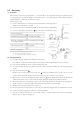
1 Phase
220-240V 50Hz
Power Source
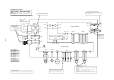
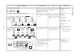
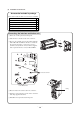
● Inspection of electronic expansion valve
To test if there is voltage.
(Voltage is only applied to the electronic expansion valve when the valve angle is be-
ing changed.)
Red to white
Red to Orange
Brown to yellow
Brown to blue
If the expansion valve does not operate as shown above, it is defective.
Normal if there is approximately DC 5 V 10 seconds
after the power supply is turned on.
}
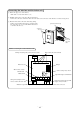
● Power supply and serial
signal inspection
1 to 2: AC220/230/240V
2 to 3: Normal if the voltage
oscillates between DC 0
and approx. 12V
● Inspection of inductor conductivity
Remove the connector and check for conductivi-
ty. It must be conductive.
● Inspect power
transistor.
Remove the fasten
terminal and test
output voltage.
*
Check fuse. There should be conductivity.
CAUTION – HIGH VOLTAGE
High voltage is produced in the control box. Don’t touch
electrical parts in the control box for 5 minutes after the
unit is stopped.
u * Check these points with the power supply on.
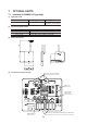
SSCM80ZG-S
Black
Red
White
Yellow/Green
BK
RD
WH
Blue
Yellow
BL
Brown
BR
Gray
GR
Orange
OR
YL
Y/G
Color symbol
LED E
ERROR
Tho-D Tho-CTho-A Tho-R
● Inspection of resistance value of sensor.
Remove the connector and check the resistance value.
See the section of sensor characteristics on page 91.
● Display lamp inspection
• LED E (Abnormality display lamp - Red) ON or flashing: Protection function operating
*