
Specifications


-
109
-
No.
1
2
3
4
Z
Y
X
Z
Y
X
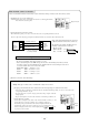
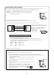
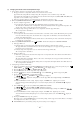
See the super link adapter’s manual concerning connections to the super link adapter.
1
Cut jumper wire (J2) on the circuit board.
Caution: This device cannot be used together with the wireless remote
control which is supplied with the indoor unit.
2
Connections between the interface and super link adapter
3
Fasten the super link adapter cable with clamps.
CNT connector functions
Super link adapter connection
Jumper wire (J2)
Super link
adapter
Super link
adapter
terminal block
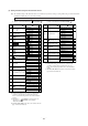
Interface side
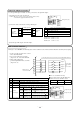
Within 200 m 0.5 mm
2
× 3 cores
Within 300 m 0.75 mm
2
× 3 cores
Within 400 m 1.25 mm
2
× 3 cores
Within 600 m 2.0 mm
2
× 3 cores
Shielded wire
Vinyl cabtyre round cord
Vinyl cabtyre round cable
Vinyl insulated wirevinyl sheathed cable for control
Z terminal: black wire
Y terminal: white wire
X terminal: red wire
Names of recommended signal wires
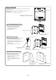
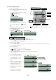
Turning the contacts ON/OFF, the off/running status of the air conditioner can be monitored from the External control unit (remote display).
1
Connect a locally procured remote control
unit to the CNT terminal.
2
In case of the pulse input, cut off the
jumper wire “J1” on the main unit PCB.
3
When setting at Operation
permission/prohibition Mode, cut off the
jumper wire “J3”.
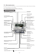
X
R1~4
are for the DC 12V relay
X
R5
is a DC 12/24 or AC 220~240V relay
CNT connector (local) maker, model
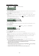
Pulse input
(J1 cut)
Pulse input
(J1 cut)
Input
Output
Operation output
Heating output
Malfunction output
ON output (X
R1
= ON) during air conditioner operation
ON output (X
R2
= ON) during heating operation
ON output (X
R3
= ON) during compressor operation
ON output (X
R4
= ON) during an abnormal stop
Content
Jumper wire (J3)
In the operation permited/prohibited mode, remote control operations are allowed only when the input is turned ON.
X
R1
X
R5
X
R1
X
R2
X
R3
X
R4
1
2
3
4
5
6
X
R2
X
R3
X
R4
X
R5
CNT connector
0.3 mm
2
(Keep the distance between the relay and the CNT terminal within 2 m.)
Common
Power supply
DC 12/24 V
or
AC 220~240V
Output 1
Output 2
Output 3
Output 4
Input
Jumper wire (J1)
Connector
Terminals
Molex
Molex
5264-06
5263T
X
R5
Air conditioner ON/OFF is inverted
depending on the pulse signal at OFF ON.
X
R5
Air conditioner ON/OFF is inverted
depending on the pulse signal at OFF ON.
Output 1
Output 2
Output 3
Output 4
Compressor
operation output
Remote
control input
Input
Level input
(At shipment)
Level input
(At shipment)
External control
(At shipment)
External control
(At shipment)
Operation permission
/prohibition (J3 cut)
Operation permission
/prohibition (J3 cut)
X
R5
X
R5
OFF
ON
ON
OFF
Air conditioner OFF
Air conditioner OFF
X
R5
X
R5
OFF
ON
ON
OFF
Air conditioner ON
Air conditioner OFF