
Specifications


-
112
-
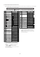
EXTERNAL INPUT
WIRED REMOCON
OPE PERMISSION
CUSTOM
AUTO RESTART
LO TEMP
DIRT PREVENT
COOL ONLY
HI CEIL
PANEL
50/60
EXTERNAL INPUT
WIRED REMOCON
OPE PERMISSION
CUSTOM
AUTO RESTART
LO TEMP
DIRT PREVENT
COOL ONLY
HI CEIL
PANEL
50/60
Z
Y
X
Z
Y
X
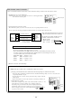
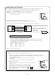
• The maximum total length should be 600 m.
• Be sure to use shielded cable. (Type: 0.3 mm
2
× 3 cores)
• If the extended length exceeds 100m, change the wire size to the following sizes. However, inside
the remote control case, the maximum wire size should be 0.5 mm
2
or less. Change the wire size in
accordance with the wires connected near the outside.
Within 100 ~ 200 m ······ 0.5 mm
2
× 3 cores
Within 300 m ···· 0.75 mm
2
× 3 cores
Within 400 m ···· 1.25 mm
2
× 3 cores
Within 600 m ······ 2.0 mm
2
× 3 cores
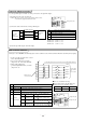
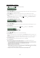
Multiple units (up to 16 units) can be controlled with a single remote control.
1 For group control, install connection cables between the unit and package air conditioner indoor units.
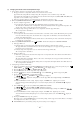
• Connect the cables to terminals X, Y and Z in the indoor unit. Each terminal has polarity, so be sure to connect wires to the
corresponding terminals at each end.
• Use cables with a size of 0.5 mm
2
or larger. (cables that are large enough to endure the
routing required)
• Keep the total length of connection cables and remote control wiring to within 600 m.
2 Set the address in each unit.
Set the address of using the rotary switch on the indoor unit's printed circuit board inside
each unit. (“0” ~ “F”)
Set the addresses in each group so that there is no overlapping of addresses.
After turning on the power, the indoor unit’s address is displayed when the Air
Conditioner No. button on the remote control is pressed, so check if the indoor unit
addresses is displayed in the remote control’s display when the and buttons
are pressed to select each unit.
(1) Wired remote control connection
Control of multiple units with a remote control
Cautions when extending the connection cable length
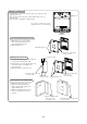
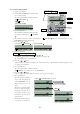
Cut jumper wire “J2 (WIRED REMOCON)” on the indoor unit's printed circuit
board.
Caution: Both the wired remote control and the wireless remote control supplied with the
indoor unit cannot be used together.
Strip off the sheath material from the connection
cable wires inside the wired remote control case.
The length of wire with the sheathing removed
should be as shown below for each wire.
Black: 195 mm
White: 205 mm
Red: 215 mm
1
Fasten the connection cables with clamps.3
Connect the indoor unit’s printed circuit board and remote control.
The terminals have polarity, so be sure to connect the wires to the corresponding terminal on each end.
Be sure to strip off the only the proper length of sheath material from each connection cable in the interface unit.
2
Please see the instructions in the wired remote control’s manual concerning connections to the wired remote control.
Note (1) Refer to “7.1 Interface kit” when connecting the wired remote control to SKM models 20 - 50.
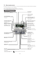
Jumper wire (J2)
Rotary
switch
Sheath material
removal length
Remote
control
terminal
block
Connection cable
0.3 mm
2
(recommended)
~ 0.5 mm
2
(maximum)
Wired
terminal
block
Indoor unit
side
Z terminal: black wire
Y terminal: white wire
X terminal: red wire