
Specifications


-
113
-
g) Use a cord clamp to attach the remote control
cord to the wall.
h) Set the functions according to the types of
indoor unit. (Refer to 112 page).
2) Recessed fitting
a) The Electrical box and remote control (shield wire
must be use in case of extension) are first
embedded.
(a) Selection of installation location
Avoid the following locations
1) Direct sunlight.
2) Close to heating device.
3) Highly humid or water splashing area.
4) Uneven surface.
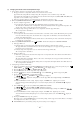
(b) Installation procedure
1) Exposed fiting
a) Open the remote control cover and unscrew
the screw located beneath the switch.
b) Open the remote control case.
• Put a screw driver (flat-head) into the concavity
made on the upper part of a remote control and
twist it lightly to open the casing.
c) The cord of a remote control can only be
pulled out in the upward direction.
• Cut off with nippers or a knife a thin walled
part made on the upper end of the rmote control
bottom casing, and then remove burrs with a
file or the like.
d) Fix the remote control bottom casing onto a
wall with two wood screws supplied as ac-
cessories.
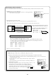
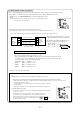
e) Connect the remote control to the terminal
block. Connect the terminals of the remote
control to the indoor unit (SKM20~50 :
interface kit) with the same numbers. Because
the terminal block has polarity, the device
becomes inoperative if there are wrong
connections.
Terminals: xRed wire, YWhite wire, ZBlack wire
• Use a cord of 0.3mm
2
(recommended) -
0.5mm
2
(maximum) for a remote control cord.
Remove a sheathe of the remote control cord
for the section laid within the remote control
casing.
Thin walled part
Upper
Lower
Lower case
Upper
Lower
Lower case
Upper
Lower
Board
Wiring
XYZ
Red White Black
Upper case
Remote
control cord
Electrical box
Not included
Upper
Lower
Cable outlet
Lower case
Upper
Lower
Cable outlet
Cut off with a knife or the like thin walled parts
intended for screw holes, and then fix it with
screws.
Two M4 screws
(Head diameter must be 8mm)
(not included)
(This side is not grounded)
Earth wiring
Remote control
switch
Remote control cord
(Shielded wire)
Indoor unit
(SKM20~50 : Interface kit)
Length of the
section where a
sheath is removed
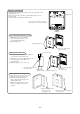
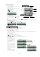
b) Remove the upper case to the remote control.
c) Attach the lower case to the Electricl box with
two M4 screws. (Head diameter must be 8 mm).
Choose either of the following two positions in
fixing it with screws.
d) Connect the remote control cord to the remote
control.
Refer to [Exposed fitting].
e) Installation work is completed by replacing the
top casing onto the bottom casing as before.
f) Set the function switch according to the type of
the indoor unit. (Refer to 112 page)
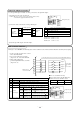
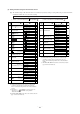
Precation in Extending the Remote control cord
Maximum total extension 600m.
The cord should be a shielded wire.
● For all types : 0.3mm
2
× 3 cores
Note (1) Use cables up to 0.5mm
2
(maximum) for those laid inside
the remote control unit casing and connect to a different
size cable at a vicinity point outside the remote control unit,
if necessary.
100.Within 100-200m…………0.55 mm
2
× 3 cores
Within 300m…………0.75 mm
2
× 3 cores
Within 400m…………1.25 mm
2
× 3 cores
Within 600m…………2.05 mm
2
× 3 cores
●
The shielded wire should be grounded at one side only.
t
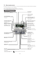
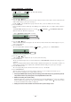
(2) Installation of wired remote control
Black: 195mm, White: 205mm, Red: 125mm
f) Replace the top casing as before.
Screw
The length of each wire that should be left after
a sheath is removed is as follows: