
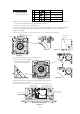
Specifications


-
84
-
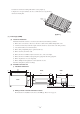
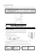
5.5 Refrigerant Piping
(1) Limit
The maximum permissible length of the refrigerant pipes for the outdoor units, and the maximum permissible height difference for
the outdoor units are as shown below.
* If the total length for all the rooms exceeds the length of chargeless refrigerant pipe, additionally charge with refrigerant accord-
ing the item 4.
¡ The diameter of the refrigerant pipe:
¡ Outdoor unit and the total connectable indoor units (class kW):
When indoor unit is above outdoor unit (A)
When indoor unit below outdoor unit (B)
Difference in height between indoor units (C)
Length for one indoor unit
Total length for all rooms
Length of chargeless refrigerant pipe*
SCM40ZG-S
30m
Max. 30m
15m
15m
Max. 40m
SCM45ZG-S
20m
SCM48ZG-S
40m
Max. 25m
Max. 25m
SCM60ZG-S
30m
SCM80ZG-S
Max. 70m
20m
40m
20m
Difference in
height between
indoor and
outdoor unit
Liquid side
Gas side
2.0 · 2.2 · 2.5 · 2.8 · 3.5kW
ø 9.52 · t 0.8
5.0 · 6.0 · 7.1kW
ø 12.7 · t 0.8
ø 6.35 · t 0.8
Class of indoor unit (kW)
Diameter of joint pipe
A
B
C
Total of indoor units (class kW)
SCM40ZG-S
5.7kW
SCM45ZG-S
7.0kW
SCM48ZG-S
8.5kW
SCM60ZG-S
11.0kW
SCM80ZG-S
13.5kW
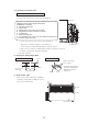
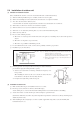
(2) Connection of refrigerant piping
¡ The service valve corresponding to each indoor unit is as illustrated in the right figure.
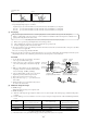
¡ Regarding the change in the sizes of gas side pipes (usage of the variable joints); if a
5.0, 6.0, 7.1 kW class indoor unit (gas side pipe 12.7) is going to be connected to the
service valves (9.52), variable joints available as accessories must be applied to the gas
side service valves.
[Examples of use of variable diameter joints]
Connection of indoor unit of Class 5.0 to A unit.
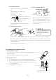
¡ Securely fit the copper packing between the service valve and the variable diameter joint to prevent shifting.
¡ Cover the pipes with tape so that dust and sand do not enter the pipe until they are connected.
[Connection of pipes]
¡ When connecting the pipes to the outdoor unit, be careful about the discharge of fluorocarbon gas or oil.
¡ Make sure to match the pipes between the indoor unit and the outdoor unit with the correct service valves.
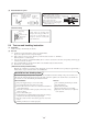
(1) Preparations
¡ Remove the flare nut (from both
liquid and gas sides).
¡ Remove the flare nut (from both
liquid and gas sides).
¡ Fit the removed flare nut to the joint pipe, and then flare it.
A dimensions
Liquid side: ø 6.35:9.1dia
Gas side:
ø 9.52: 13.2dia
ø 12.7: 16.6dia
ø9.52
Earth screw
Gas
Gas
side
service
valve
Liquid
Liquid
side
service
valve
Service valve
for room D
Service valve
for room C
Service valve
for room B
Service valve
for room A
ø9.52
ø9.52
ø9.52
ø6.35 pipe
ø12.7 pipe
Indoor unit
5.0 kW class
Liquid side service valve (ø6.35)
Gas side service
valve (ø9.52)
Copper packing Variable diameter joint (ø9.52-ø12.7)
Service
valve for room A
Indoor
Remove
Push
Outdoor
Remove
Push
90+0.5˚
A