
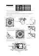
Specifications


-
85
-
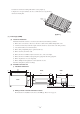
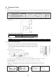
(4) Additional refrigerant charge
¡ SCM40, 48 type
Additional refrigerant charge is not required at all
¡ SCM45, 60, 80 type
(a) When the total refrigerant pipe length for all the rooms exceeds the length of the uncharged pipe, additional refrigerant is
required.
(b) For this multi type room air conditioner, it is not necessary to charge the refrigerant for the total maximum length in all the
rooms.
*1: Charge amount at the time of shipment.
(c) Ensure that there are no gas leaks from the pipe joints by using a leak detector or soap water.
Model
SCM60ZG-S
Charged pipe length
(Amount of uncharged refrigerant) *1
Maximum total pipe length for all rooms
(Maximum amount of refrigerant)
On site additional charge
20g/m
30m (2200g) 40m (2400g)
SCM80ZG-S
20g/m
40m (3150g) 70m (3750g)
SCM45ZG-S
20g/m
20m (1600g)
30m (1800g)
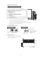
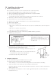
(2) Connection
Indoor Outdoor
¡ Secure the nut with a specified tightening
torque to avoid any gas leaks.
¡ Secure the nut with a specified tightening
torque to avoid any gas leaks.
Liquid side
Gas side
Liquid side
Gas side
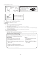
(3) Air purging
(a) Remove the cap on both gas and liquid sides before starting operation.
(b) After completing the operation, do not forget to tighten the cap (gas may leak).
(c) Conduct air purging for all connected indoor units.
¡ Since the system uses service ports differing in diameter from those found on the conventional models, a charge hose (for R22)
presently in use is not applicable.
Please use one designed specifically for R410A
¡
Please use an anti-reverse flow type vacuum pump adapter so as to prevent vacuum pump oil from running back into the system.
Oil running back into an air-conditioning system may cause the refrigerant cycle to break down.
Note: Fully open the service valves (on both liquid and gas sides) after completing air purging
To protect the global environment, use a vacuum pump that do not release flourocarbon gas into the atmosphere.
When a vacuum pump cannot be used due to certain conditions for installation, sufficient refrigerant is available for air
purging with refrigerant for the outdoor unit.
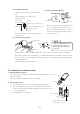
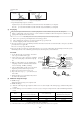
Procedure
1 Secure all flare nuts on both indoor and outdoor
sides to prevent leaks from the pipes.
2 Connect the service valves, charge hose, manifold
valve and vacuum pump as shown in the right fig-
ure.
3 Fully open the handle Lo for the manifold valve,
and pump a vacuum for 15 minutes. Ensure that the
meter is indicating -0.1 MPa (-76cmHg).
4 After vacuuming, fully open the service valve (both
liquid and gas sides) with a hexagon wrench.
5 Remove the charge hose from service port.
6 Repeat the above steps 1 ~ 5 for all connected
indoor units.
7 Ensure that there are no gas leaks from the joints in
the indoor and outdoor units.
Compound
pressure
gauge
Pressure
gauge
Handle Hi
Handle Lo
-0.1MPa
(-76cmHg)
Service valve
for room B
Service valve
for room A
Service valve
(two-way valve)
Service valve
(three-way valve)
Service Port
Open
Open
Gauge Manifold
(Designed speci-
fically for R410A)
Charge hose
(Designed speci-
fically for R410A)
Vacuum
pump
Vacuum pump adapter
(Anti-reverse flow type).
(Designed specifically for R410A)
Charge hose
(Designed specifically for R410A)
¡ Specified tightening torques are as follows:
Liquid side (ø 6.35): 17mm in width across flat of the flare nut: 14.0-18.0 N·m (1.4-1.8 kgf·m)
Gas side (ø 9.52): 22mm in width across flat of the flare nut: 33.0-42.0 N·m (3.3-4.2 kgf·m)
Gas side (ø 12.7): 24mm in width across flat of the flare nut: 49.0-61.0 N·m (4.9-6.1 kgf·m)