MELSEC-Q/L/F Structured Programming Manual (Fundamentals)
SAFETY PRECAUTIONS (Read these precautions before using this product.) Before using MELSEC-Q, -L, or -F series programmable controllers, please read the manuals included with each product and the relevant manuals introduced in those manuals carefully, and pay full attention to safety to handle the product correctly. Make sure that the end users read the manuals included with each product, and keep the manuals in a safe place for future reference.
CONDITIONS OF USE FOR THE PRODUCT (1) Mitsubishi programmable controller ("the PRODUCT") shall be used in conditions; i) where any problem, fault or failure occurring in the PRODUCT, if any, shall not lead to any major or serious accident; and ii) where the backup and fail-safe function are systematically or automatically provided outside of the PRODUCT for the case of any problem, fault or failure occurring in the PRODUCT.
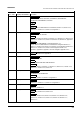
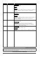
REVISIONS The manual number is written at the bottom left of the back cover. Print date Manual number Revision Jul., 2008 SH(NA)-080782ENG-A First edition Jan., 2009 SH(NA)-080782ENG-B Model Addition Q00UJCPU, Q00UCPU, Q01UCPU, Q10UDHCPU, Q10UDEHCPU, Q20UDHCPU, Q20UDEHCPU, FX series Addition MANUALS Correction Generic Terms and Abbreviations in This Manual, Section 1.3, Section 4.3.3, Section 4.3.4, Section 4.4.1, Section 4.4.2, Appendix 1 Jul.
Print date Manual number Jul., 2011 SH(NA)-080782ENG-J Revision Model Addition L02CPU-P, L26CPU-PBT Addition Section 5.2.5 Correction Section 1.3, Section 1.4, Section 1.5, Section 4.2.6, Section 4.2.7, Section 4.4.2, Section 4.4.3, Section 4.4.4, Section 5.1.3, Section 5.1.6, Section 5.2, Section 5.2.2 May, 2012 SH(NA)-080782ENG-K "PLC" was changed to "programmable controller". Model Addition FX3GC Correction INTRODUCTION, MANUALS, Section 1.2, Section 1.3, Section 1.5, Section 4.1.3, Section 4.2.
INTRODUCTION Thank you for purchasing the Mitsubishi MELSEC-Q, -L, or -F series programmable controllers. Before using this product, please read this manual and the relevant manuals carefully and develop familiarity with the programming specifications to handle the product correctly. When applying the program examples introduced in this manual to an actual system, ensure the applicability and confirm that it will not cause system control problems. CONTENTS SAFETY PRECAUTIONS ...............................
4.2.9 EN and ENO ................................................................................................................................ 4 - 13 4.3 Labels 4.3.1 4.3.2 4.3.3 4.3.4 4.3.5 4.3.6 Global labels ................................................................................................................................ 4 - 15 Local labels..................................................................................................................................
APPENDICES App - 1 to App - 14 Appendix 1Correspondence between Generic Data Types and Devices App - 2 Appendix 2Character Strings that cannot be Used in Label Names and Data Names App - 6 Appendix 3Recreating Ladder Programs App - 9 Appendix 3.1Procedure for creating a structured program ................................................................... App - 9 Appendix 3.2Example of creating a structured program.....................................................................
MANUALS The manuals related to this product are listed below. Please place an order as needed.
1 OVERVIEW 1 OVERVIEW STRUCTURED DESIGN OF SEQUENCE PROGRAMS 2 1.3 Terms . . . . . . . . . . . . . . . . . . . . . . . . . . . . . . . . . . . . . . . . . . . . . . . . . . . . . . . . 1-6 1.4 Features of Structured Programs . . . . . . . . . . . . . . . . . . . . . . . . . . . . . . . . . . . 1-7 1.5 Applicable CPU Modules . . . . . . . . . . . . . . . . . . . . . . . . . . . . . . . . . . . . . . . . . 1-8 1.6 Compatible Software Package . . . . . . . . . . . . . . . . . . . . . . . . . . . .
1.1 Overview This manual describes program configurations and content for creating sequence programs using a structured programming method, and provides basic knowledge for writing programs. 1.2 Purpose of This Manual This manual explains programming methods, programming languages, and other information necessary for creating structured programs. Manuals for reference are listed in the following table according to their purpose.
For details of instructions used in each programming language, refer to the section 3 on the next page. Purpose Ladder Simple Project SFC GX Works2 Beginner's Manual Simple Project Structured Project Simple Project Structured Project Details Outline *1 Details Outline ST Ladder SFC Structured Project GX Works2 Version 1 Operating Manual Details Outline Details Outline *1 Details Outline Structured ladder/ FBD ST Outline Details Outline Details *1: MELSAP3 and FX series SFC only 1.
(3) Details of instructions in each programming language (for QCPU (Q mode)/LCPU) Purpose MELSEC-Q MELSECProgramming Manual for MELSEC-Q/L Q/L MELSEC-Q/L/QnA /Structured module to Structured Programming Manual Programming Programming Manual Programming be used Manual Manual Process Common Special Application Common PID Control Control Fundamentals Instructions Instructions Functions Instructions Instructions SFC Instructions MELSECQ/L/F Structured Programming Manual Learning details of programmable All
1 Purpose MELSECQ/L/F Structured Programming Manual Fundamentals FXCPU Structured Programming Manual Device & Common Basic & Applied Instruction Application Functions Learning the types and details of basic/ Using ladder application instructions, language descriptions of devices and parameters Using SFC language Learning details of specifications, functions, and instructions of SFC Learning the fundamentals for creating a structured program Using structured ladder/FBD/ ST language Learning the des
1.3 Terms This manual uses the generic terms and abbreviations listed in the following table to discuss the software packages and programmable controller CPUs. Corresponding module models are also listed if needed.
1 OVERVIEW 1.4 Features of Structured Programs This section explains the features of structured programs. (1) Structured design A structured design is a method to program control content performed by a programmable controller CPU, which are divided into small processing units (components) to create hierarchical structures. A user can design programs knowing the component structures of sequence programs by using the structured programming. The following are the advantages of creating hierarchical programs.
1.5 Applicable CPU Modules The following table shows the applicable CPU modules for programs in the Structured project. Table 1.
2 OVERVIEW 1 STRUCTURED DESIGN OF SEQUENCE PROGRAMS STRUCTURED DESIGN OF SEQUENCE PROGRAMS 2 4 PROGRAM CONFIGURATION What is a Structured Sequence Program? . . . . . . . . . . . . . . . . . . . . . . . . . . . . 2-3 5 WRITING PROGRAMS 2.2 A APPENDICES What is a Hierarchical Sequence Program?. . . . . . . . . . . . . . . . . . . . . . . . . . . 2-2 I INDEX 2.
2.1 What is a Hierarchical Sequence Program? The hierarchy is to create a sequence program by dividing control functions performed in a programmable controller CPU into a number of levels. In higher levels, the processing order and timing in a fixed range is controlled. With each move from a higher level to a lower level, control content and processes are progressively subdivided within a fixed range, and specific processes are described in lower levels.
2.2 What is a Structured Sequence Program? A structured program is a program created by components. Processes in lower levels of hierarchical sequence program are divided to several components according to their processing information and functions. Each component is designed to have a high degree of independence for easy addition and replacement. The following shows examples of the process that would be ideal to be structured. • A process that is used repeatedly in a sequence program.
MEMO 2-4
3 OVERVIEW 1 PROCEDURE FOR CREATING PROGRAMS STRUCTURED DESIGN OF SEQUENCE PROGRAMS 2 Procedure for Creating Sequence Programs in Structured Project . . . . . . . . . 3-2 PROGRAM CONFIGURATION 4 WRITING PROGRAMS 5 APPENDICES A I INDEX 3.
3.1 Procedure for Creating Sequence Programs in Structured Project This section explains the basic procedure for creating a sequence program in the Structured project. (1) Creating the program configuration Procedure Create program files. Create tasks. (2) Creating POUs Procedure Create POUs. Define global labels. Define local labels. Edit the programs of each POU. (3) Setting the programs Procedure Register the POUs in the tasks. (4) Compiling the programs Procedure Compile the programs.
4 OVERVIEW 1 PROGRAM CONFIGURATION STRUCTURED DESIGN OF SEQUENCE PROGRAMS 2 4.3 Labels . . . . . . . . . . . . . . . . . . . . . . . . . . . . . . . . . . . . . . . . . . . . . . . . . . . . . . . 4-15 4.4 Method for Specifying Data . . . . . . . . . . . . . . . . . . . . . . . . . . . . . . . . . . . . . . 4-21 4.5 Device and Address . . . . . . . . . . . . . . . . . . . . . . . . . . . . . . . . . . . . . . . . . . . . 4-38 4.6 Index Setting. . . . . . . . . . . . . . . . . . . . . . . . . .
4.1 Overview of Program Configuration A sequence program created in the Structured project is composed of program files, tasks, and POUs. For details of program components, refer to the following sections. For projects: Section 4.1.1 Project For program files: Section 4.1.2 Program files For tasks: Section 4.1.3 Tasks For POUs: Section 4.2 POUs The following figure shows the configuration of program files, tasks, and POUs in the project.
4.1.1 Project A project is a generic term for data (such as programs and parameters) to be executed in a programmable controller CPU. One or more program files need to be created in a project. 4.1.2 Program files One or more tasks need to be created in a program file. (Created tasks are executed under the control of the program file.
4.1.3 Tasks A task is an element that contains multiple POUs, and it is registered to a program file. One or more programs of POU need to be registered in a task. (Functions and function blocks cannot be registered in a task.
4.2 POUs A POU (abbreviation for Program Organization Unit) is a program component defined by each function. 4.2.1 Types of POU The following three types can be selected for each POU according to the content to be defined. • Program • Function • Function block Each POU consists of a program and local labels*1. A process can be described in a programming language that suits the control function for each POU.
4.2.2 Program A program is an element that is stated at the highest level of POU. Functions, function blocks, and operators are used to edit programs. Program Function Function block Operator Sequence programs executed in a programmable controller CPU are created by programs of POU. For a simplest sequence program, only one program needs to be created and registered to a task in order to be executed in a programmable controller CPU.
4.2.4 Function blocks Functions, function blocks, and operators are used to edit function blocks. Function blocks can be used by calling them from programs or function blocks. Note that they cannot be called from functions. Function Function block Function block Operator Function blocks can retain the input status since they can store values in internal and output variables.
4.2.6 Ladder blocks In the structured ladder/FBD language, a program is divided into units of ladder blocks. In the ST language, ladder blocks are not used. ● Ladder block labels A ladder block label can be set to a ladder block. A ladder block label is used to indicate a jump target for the Jump instruction. Ladder block label 4-8 4.2 POUs 4.2.
4.2.7 Programming languages for POUs Two types of programming language are available for programs of POU. The following explains the features of each programming language. (1) ST: Structured text Control syntax such as selection branch by conditional syntax or repetitions by iterative syntax can be described in the structured text language, as in the high-level language such as C language. Clear and simple programs can be written by using these syntax.
4.2.8 Functions, function blocks, and operators The following table shows differences among functions, function blocks, and operators. Table 4.2.
(2) Internal variables A function does not use internal variables. It uses devices assigned directly to each input variable and repeats operations. (a) A program that outputs the total of three input variables (When using a function (FUN1)) Function X0 D109 D109 FUN1 D110 D110 D111 D111 D120 A function block uses internal variables. Different devices are assigned to the internal variables for each instance of function blocks.
(3) Creating instances When using function blocks, create instances to reserve internal variables. Variables can be called from programs and other function blocks by creating instances for function blocks. To create an instance, declare as a label in a global label or local label of POU that uses function blocks. Same function blocks can be instantiated with different names in a single POU.
4.2.9 EN and ENO An EN (enable input) and ENO (enable output) can be appended to a function and function block to control their execution. A Boolean variable used as an executing condition of a function is set to an EN. A function with an EN is executed only when the executing condition of the EN is TRUE. A Boolean variable used as an output of function execution result is set to an ENO. The following table shows the status of ENO and the operation result according to the status of EN. Table 4.2.
● Usage example of EN and ENO No Control description When the EN input is directly connected from the left power rail, the EN input is always TRUE and ➀ the instruction is always executed. If the ADD_E instruction is used in this manner, the operation result is the same as the ADD instruction without the EN input.
4.3 Labels Labels include global labels and local labels. 4.3.1 Global labels The global labels are labels that can be used in programs and function blocks. In the setting of a global label, a label name, a class, a data type, and a device are associated with each other. 4.3.2 Local labels The local labels are labels that can be used only in declared POUs. They are individually defined per POU. In the setting of a local label, a label name, a class, and a data type are set. 4 4.3 Labels 4.3.
4.3.3 Label classes The label class indicates from which POU and how a label can be used. Different classes can be selected according to the type of POU. The following table shows label classes. Table 4.3.
4.3.4 Setting labels Labels used in a program require setting of either global label or local label. The following describes setting examples of the arguments g_int1 and g_int2 of the DMOV instruction. X0 g_int1 DMOV EN ENO s d g_int2 ● Using the arguments of the DMOV instruction as global labels Set the Class, Label Name, Data Type, Device, and Address. ● Using the arguments of the DMOV instruction as local labels Set the Class, Label Name, and Data Type. PROGRAM CONFIGURATION 4 4.3 Labels 4.3.
4.3.5 Data types Labels are classified into several data types according to the bit length, processing method, or value range. (1) Elementary data types The following data types are available as the elementary data type.*1 • Boolean type (bit): Represents the alternative status, such as ON or OFF. • Bit string type (word (unsigned)/16-bit string, double word (unsigned)/32-bit string): Represents bit arrays. • Integer type (word (signed), double word (signed)): Handles positive and negative integer values.
(2) Generic data types Generic data type is the data type of labels summarizing some elementary data types. Data type name starts with 'ANY'. ANY data types are used when multiple data types are allowed for function arguments and return values. Labels defined in generic data types can be used in any sub-level data type.
4.3.6 Expressing methods of constants The following table shows the expressing method for setting a constant to a label. Table 4.3.6-1 Constant expressing method Constant Expressing method type Bool Input FALSE or TRUE, or input 0 or 1. TRUE, FALSE Binary Append '2#' in front of a binary number. 2#0010, 2#01101010 Octal Append '8#' in front of an octal number. 8#0, 8#337 Decimal Directly input a decimal number, or append 'K' in front of a decimal number.
4.4 Method for Specifying Data The following shows the six types of data that can be used for instructions in CPU modules. Bit data ...................... Section 4.4.1 Numeric data Integer data Word (Signed) data ........ Section 4.4.2 Double word (Signed) data Real number data Character string data .... Section 4.4.5 Time data ....Section 4.4.6 .. Section 4.4.3 Single-precision real data ............ Section 4.4.4 (1) Double-precision real data ............Section 4.4.
4.4.1 Bit data Bit data are data handled in units of 1 bit, such as contacts and coils. 'Bit devices' and 'bit-specified word device' can be used as bit data. (1) Using bit devices A bit device is specified in unit of one point. One point of M0 is the target bit device M0 EN SET ENO d Y10 One point of Y10 is the target bit device (2) Using word devices (a) By specifying a bit number for a word device, 1/0 of the specified bit number can be used as bit data.
4.4.2 Word (16 bits) data Word data are 16-bit numeric value data used in basic instructions and application instructions. The following shows the two types of word data that can be handled in CPU modules. • Decimal constants ................ -32768 to 32767 • Hexadecimal constants ........ 0000H to FFFFH For word data, word devices and digit-specified bit device can be used. Note that word data cannot be specified using digit specification for direct access inputs (DX) and direct access outputs (DY).
(b) The following table shows the numeric values that can be used as source data when digits are specified at the source s . Table 4.4.
(2) Using word devices A word device is specified in unit of one point (16 bits). X010 100 EN s MOV ENO d D0 One point (16 bits) of D0 is the target word device 1. When performing the process with digit specification, a desired value can be used for the start device number of bit devices. 2. Digits cannot be specified for direct access inputs/outputs (DX, DY). PROGRAM CONFIGURATION 4 4.4 Method for Specifying Data 4.4.
4.4.3 Double word (32 bits) data Double word data are 32-bit numeric value data used in basic instructions and application instructions. The following shows the two types of double word data that can be handled in CPU modules. • Decimal constants ................ -2147483648 to 2147483647 • Hexadecimal constants ........ 00000000H to FFFFFFFFH For double word data, word devices and digit specification for bit devices can be used.
(b) The following table shows the numeric values that can be used as source data when digits are specified at the source s . Table 4.4.
1. When performing the process with digit specification, a desired value can be used for the start device number of bit devices. 2. Digits cannot be specified for direct access inputs/outputs (DX, DY). (2) Using word devices Devices used in lower 16 bits are specified for a word device. 'Specified device number' and 'specified device number +1' are used for instructions that process 32-bit data.
4.4.4 Single-precision real/double-precision real data Single-precision real/double-precision real data are 32-bit floating-point data used in basic instructions and application instructions. Real number data can be stored only in word devices. For FXCPU, double-precision real data is not supported. (1) Single-precision real (single-precision floating-point data) Devices used in lower 16 bits are specified for instructions that use real number data.
M0 EDMOV EN ENO d Var_R100 Transfers real number data Var_D0 Four points (64 bits) of D0, D1, D2, and D3 are the target word devices Four points (64 bits) of R100, R101, R102, and R103 are the target word devices Remark 1) Floating-point data are represented by four word devices. [Sign] 1. [Fraction] 2 [Exponent] The following explains the bit configuration and its meaning when floating-point data are internally represented.
(3) Precautions for when setting input values of single-precision real data/double-precision real data from the programming tool (a) Single-precision real Single-precision real data are processed as 32-bit single precision in the programming tool, and thus the number of significant figures becomes approximately 7. If the input value of single-precision real data exceeds 7 digits, the 8th digit is rounded.
1. Floating-point data in a CPU module can be monitored by the monitoring function of the programming tool. 2. To express 0 in floating-point data, set all of the following bits to 0. (a) Single-precision floating-point data: b0 to b31 (b) Double-precision floating-point data: b0 to b63 3.
4.4.5 String data String data are character data used in basic instructions and application instructions. From the specified character to the NULL code (00H) that indicates the end of the character string are the target string data. (1) When the specified character is NULL code The NULL code is stored by using one word.
4.4.6 Time data Time data are used in time type operation instructions of application functions. Specify time data in the T#10d20h30m40s567ms form. For example. the following adds ‘1 Day, 2 Hours, 3 Minutes, and 4 Seconds’ to ‘10 Days, 20 Hours, 30 Minutes, 40 Seconds, and 567 Milliseconds’. T#10d20h30m40s567ms g_time1 T#1d2h3m4s ADD_TIME _IN1 _IN2 g_time1 g_time2 Each value of time data can be specified within the following range. Table 4.4.
4.4.7 Arrays An array represents a consecutive aggregation of same data type labels. Arrays can be defined by the elementary data types or structures. ( GX Works2 Version 1 Operating Manual (Structured Project)) The maximum number of arrays differs depending on the data types.
[Structured ladder/FBD] [ST] FOR Index1:=0 TO 4 BY 1 DO INC(TRUE,Var_D0[Index1]); END_FOR; 1. When a label or a device is specified for an array index, the operation is performed with a combination of multiple sequence instructions. Therefore, if an interruption occurs during the operation of the array label, an unintended operation result may be produced. When using interrupt programs, use interrupt disable/enable instructions (DI/EI instructions) as necessary. 2.
4.4.8 Structures A structure is an aggregation of different data type labels. Structures can be used in all POUs. To use structures, first create the configuration of structure, and define a structure label name for the created structure as a new data type ( GX Works2 Version 1 Operating Manual (Structured Project)) To use each element of structure, append an element name after the structure label name with '.' as a delimiter in between. Example) When using the element of the structured data dut_a1 .
4.5 Device and Address This section explains the method for expressing programmable controller CPU devices. The following two types of format are available. • Device: This format consists of a device name and a device number. • Address: A format defined in IEC61131-3. In this format, a device name starts with %. 4.5.1 Device Device is a format that uses a device name and a device number. Example) X0 W35F Device name Device number For details of devices, refer to the following manuals.
4.5.2 Address Address is a format defined in IEC61131-3. The following table shows details of format that conforms to IEC61131-3. Table 4.5.2-1 Address definition specifications Start 1st character: 2nd character: data size position 3rd character and later: I Input (Omitted) Bit Numeric characters used for Q Output X Bit detailed classification W Word (16 bits) D Double word (32 bits) numbers. L Long word (64 bits)*1 A period may be omitted.
4.5.3 Correspondence between devices and addresses This section explains the correspondence between devices and addresses. (1) Correspondence between devices and addresses The following table shows the correspondence between devices and addresses. (a) QCPU (Q mode)/LCPU Table 4.5.3-1 Correspondence between devices and addresses (1/2) Device Input device and address Address Device Address X Xn %IXn X7FF %IX2047 Output Y Yn %QXn Y7FF %QX2047 Internal relay M Mn %MX0.n M2047 %MX0.
Table 4.5.3-1 Correspondence between devices and addresses (2/2) Example of correspondence between Expressing method Device Device device and address Address Device Address Step relay S Sn %MX2.n S127 %MX2.127 SFC transition device TR TRn %MX18.n TR3 %MX18.3 SFC block device BL BLn %MX17.n BL3 %MX17.3 Link input Jx\Xn %IX16.x.n J1\X1FFF %IX16.1.8191 Link output Jx\Yn %QX16.x.n J1\Y1FFF %QX16.1.8191 Link relay Jx\Bn %MX16.x.1.
(2) Digit specification of bit devices The following table shows the correspondence between devices and addresses when specifying digits of bit devices. Table 4.5.3-3 Correspondence of formats with digit specification Device K[Number of digits][Device name][Device number] (Number of digits: 1 to 8) Address %[Position of memory area][Data size]19.[Number of digits].[Classification].[Number] (Number of digits: 1 to 8) • Correspondence examples Device Address K1X0 %IW19.1.0 K4M100 %MW19.4.0.
4.6 Index Setting (1) Overview of the index setting (a) The index setting is an indirect setting that uses index registers. When the index setting is used in a sequence program, the device consists of ‘directly specified device number’ + ‘content of index register’. For example, when D2Z2 is specified and the value of Z2 is 3, D(2+3)=D5 is set as the target. (b) For Universal model QCPU, LCPU, and FXCPU, indexes can be set in 32-bit range in addition to 16-bit range.
2) Devices with restrictions on index registers Device Description Example TS0Z0 Only Z0 or Z1 can be used for contacts or T TC1Z1 100 coils of the timer. CS0Z1 Only Z0 or Z1 can be used for contacts or C CC1Z0 100 coils of the counter. OUT_T EN ENO s1 s2 OUT_C EN ENO s1 s2 (c) Devices that can be used for the index setting (for FXCPU) The following table shows the devices that can be used for the index setting.
(d) The following figure shows the examples of index setting and their actual processing devices. (With the setting of Z0=20 and Z1=5) Ladder example X1 K20 EN s MOV ENO d Z0 K-5 MOV EN ENO s d Z1 X1 MOV ENO d K1M38Z1 K20 EN s MOV ENO d Z0 K-5 MOV EN ENO s d Z1 D0Z0 MOV EN ENO s d K3Y12FZ1 K2X50Z0 EN s X0 X1 K2X64 Description K2X50Z0 EN s MOV ENO d K1M33 K2X(50 + 14) = K2X64 Converts K20 to a hexadecimal number.
(a) Specifying a range of index registers used for a 32-bit index setting 1) Values from 2147483648 to 2147483647 can be set to index registers. The following shows how the index is set.
4) Usage range of index registers The following table lists the usage range of index registers when setting indexes in 32-bit range. Since the specified index register (Zn) and next index register (Zn+1) are used for index setting in 32-bit range, make sure not to overlap index registers being used.
(b) Specifying a 32-bit index setting using 'ZZ' 1) A 32-bit index can be specified to the index register by specifying an index using 'ZZ', for instance, 'ZR0ZZ4'. The following figure shows the 32-bit index setting using 'ZZ'. M0 K100000 M0 K100 DMOVP EN ENO s d MOVP EN ENO s d Set 100000 to Z4 and Z5. Z4 Set 32-bit (Z4, Z5) index to ZR. ZR(0+100000) indicates ZR100000.
5) The following figure shows the examples of 32-bit index setting using 'ZZ' and their actual processing devices. (With the setting of Z0 (32 bits) =100000 and Z2 (32 bits)=-20) Ladder example Actual processing device X1 X0 DMOV EN ENO s d K100000 K-20 EN s DMOV ENO d ZR1000ZZ0 EN s MOV ENO d X1 ZR101000 Z0 EN s MOV ENO d D12980 Description ZR1000Z0 D13000Z2 Z2 ZR(1000+100000) ZR101000 D(30-20) D12980 D13000Z2 Figure 4.
(4) Applying index settings to extended data registers (D) and extended link registers (W) (for Universal model QCPU (excluding Q00UJCPU), and LCPU) As an index setting can be applied to internal user devices, data registers (D) and link registers (W), the device specification by the index setting can be used within the range of extended data registers (D) and extended link registers (W).
2) Index settings that cross file registers (ZR), extended data registers (D), and extended link registers (W) Even when an index setting that crosses file registers (ZR), extended data registers (D), and extended link registers (W) is applied, an error does not occur. However, if the result of the index setting applied to file registers (ZR), extended data registers (D) or extended link registers (W) exceeds the range of the file register files, an error occurs.
(b) An index setting is applicable to both start I/O numbers of the intelligent function module and buffer memory addresses for intelligent function module devices*5. U10Z1\G0Z2 EN s MOV ENO d D0 If Z1=2 and Z2=8, then U(10+2)\G(0+8)=U12\G8 (c) An index setting is applicable to both network numbers and device numbers for link direct devices*5.
(6) Precautions (a) Using the index setting for arguments of instruction/application function/function/ function block When "Use ZZ" is checked in "Indexing Setting for ZR Device" setting in the <> tab of the PLC parameter, and Z device is used for the argument of instruction/application function/function/function block, the expression is converted to "ZZ" at the compilation. This may cause unintended device accesses.
(c) Applying the index setting in the CALL instruction The pulse can be output by using edge relays (V) with the CALL instruction. Note that the pulse cannot be output by the PLS, PLF, or pulse ( P) instruction. [When using an edge relay] [When not using an edge relay] (M0Z1 pulse is output normally.) (M0Z1 pulse is not output normally.
4.7 Libraries A library is an aggregation of data including POUs, global labels, and structures organized in a single file to be utilized in multiple projects. The following are the advantages of using libraries. • Data in library files can be utilized in multiple projects by installing them to each project. • Since library data can be created according to the functions of components, data to be reused can be easily confirmed.
4.7.1 User libraries A user library is a library for storing created structures, global labels, POUs, and other data that can be used in other projects. (1) Composition of a user library The following table shows data that can be registered in a user library. Table 4.7.1-1 Composition of a user library Name Structure Global label POU 4-56 4.7 Libraries 4.7.
4.8 Precautions on Assigning a Name This section explains the conditions for assigning a name to a label, function block instance, or structure label. • Conditions (1) Specify a name within 32 characters. (2) Do not use reserved words. For reserved words, refer to the following section. Appendix 2 Character Strings that cannot be Used in Label Names and Data Names (3) Use alphanumeric and underscores (_). (4) Do not use an underscore at the end of the name. Do not use two or more underscores in succession.
MEMO 4-58
5 OVERVIEW 1 WRITING PROGRAMS STRUCTURED DESIGN OF SEQUENCE PROGRAMS 2 4 PROGRAM CONFIGURATION Structured Ladder/FBD. . . . . . . . . . . . . . . . . . . . . . . . . . . . . . . . . . . . . . . . . . 5-13 5 WRITING PROGRAMS 5.2 A APPENDICES ST . . . . . . . . . . . . . . . . . . . . . . . . . . . . . . . . . . . . . . . . . . . . . . . . . . . . . . . . . . . 5-2 I INDEX 5.
5.1 ST The ST language is a text language with a similar grammatical structure to the C language. Controls such as conditional judgement and repetition process written in syntax can be described. This language is suitable for programming complicated processes that cannot be easily described by a graphic language (structured ladder/FBD language). 5.1.
5.1.2 Operators in ST language The following table shows the operators used in the ST program and their priorities. Table 5.1.2-1 Operators in the ST language Operator Description Example Priority Highest () Parenthesized expression (1+2)*(3+4) Function ( ) Function (Parameter list) ADD_E(bo01, in01, in02, in03) ** Exponentiation re01:= 2.0 ** 4.
5.1.3 Syntax in ST language The following table shows the syntax that can be used in the ST program. Table 5.1.
(2) IF THEN conditional syntax (a) Format IF THEN ; END_IF; (b) Description The syntax is executed when the value of Boolean expression (conditional expression) is TRUE. The syntax is not executed if the value of Boolean expression is FALSE. Any expression that returns TRUE or FALSE as the result of the Boolean operation with a single bit type variable status, or a complicated expression that includes many variables can be used for the Boolean expression.
(4) IF ...ELSIF conditional syntax (a) Format IF THEN ; ELSIF THEN ; ELSIF THEN ; END_IF; (b) Description Syntax 1 is executed when the value of Boolean expression (conditional expression) 1 is TRUE. Syntax 2 is executed when the value of Boolean expression 1 is FALSE and the value of Boolean expression 2 is TRUE.
(6) FOR...DO syntax (a) Format FOR TO BY DO ; END_FOR; (b) Description The FOR...DO syntax repeats the execution of several syntax according to the value of a repeat variable. (c) Example (7) WHILE...DO syntax (a) Format WHILE DO ; END_WHILE; (b) Description The WHILE...DO syntax executes one or more syntax while the value of Boolean expression (conditional expression) is TRUE.
(8) REPEAT...UNTIL syntax (a) Format REPEAT ; UNTIL END_REPEAT; (b) Description The REPEAT...UNTIL syntax executes one or more syntax while the value of Boolean expression (conditional expression) is FALSE. The Boolean expression is evaluated after the execution of the syntax. If the value of Boolean expression is TRUE, the syntax in the REPEAT...UNTIL syntax are not executed.
(10) EXIT syntax (a) Format EXIT; (b) Description The EXIT syntax is used only in iteration syntax to end the iteration syntax in a middle of the process. When the EXIT syntax is reached during the execution of the iteration loop, the iteration loop process after the EXIT syntax is not executed. The process continues from the line after the one where the iteration syntax is ended. (c) Example 5.1.4 Calling functions in ST language The following description is used to call a function in the ST language.
5.1.5 Calling function blocks in ST language The following description is used to call a function block in the ST language. Instance name(Input variable1:= Variable1, ... Output variable1: = Variable2, ...); Enclose the assignment syntax that assigns variables to the input variable and output variable by '( )' after the instance name. When using multiple variables, delimit assignment syntax by ',' (comma).
5.1.6 Precautions when using conditional syntax and iteration syntax The following explains the precautions when creating ST programs using conditional syntax and iteration syntax. (1) Once the conditions (boolean expression) are met in the conditional syntax or iteration syntax, the bit device which is turned ON in the is always set to ON.
(2) When Q00UCPU, Q00UJCPU or, Q01UCPU is used, and the string type is applied to Boolean expression (conditional expression) with conditional syntax or iteration syntax, a compilation error may occur. • Program example which causes compilation error ST program Compilation error occurs when specifying string type data.
5.2 Structured Ladder/FBD The structured ladder/FBD is a graphic language for writing programs using ladder symbols such as contacts, coils, functions, and function blocks. 5.2.1 Standard format Contact Ladder block label Left power rail Coil Function Function block Input variables Output variables 5 In the structured ladder/FBD language, units of ladder blocks are used for programming. WRITING PROGRAMS For structured ladder, connect the left power rail and ladder symbols with lines.
5.2.2 Ladder symbols in structured ladder/FBD language The following table shows the ladder symbols that can be used in the structured ladder/FBD language. For details, refer to the following manual. MELSEC-Q/L Structured Programming Manual (Common Instructions) Table 5.2.2-1 Ladder symbols in the structured ladder/FBD language (1/2) Element Ladder symbol Description Normal *1,*2 Turns ON when a specified device or label is ON. Negation *1,*2 Turns OFF when a specified device or label is OFF.
Table 5.2.2-1 Ladder symbols in the structured ladder/FBD language (2/2) Element Network element Description Pointer branch instruction Jump Unconditionally executes the program at the specified pointer number in the same POUs. Indicates the end of a subroutine program. Function Executes a function. Function block Executes a function block. Function argument input Inputs an argument to a function or function block.
5.2.3 Executing order The following figures explain the program executing order. The operation order in a ladder block is from the left power rail to the right and from the top to the bottom. The program is executed from the left power rail to the right when the ladder is not branched and ENs and ENOs are connected in series. The program is executed from the top to the bottom, when the ladder is branched and ENs and ENOs are connected in parallel.
5.2.4 Ladder branches and compilation results When the ladder is branched, different compilation results are produced for the program after the branch depending on the program up to the branch. The following explains the precautions on compilation results depending on ladder branches. (1) When one contact is used up to the branch, the instruction of the contact is used multiple times in the compilation result. < Example > < Compilation result > The LD instructions are created using the contact.
(2) When multiple contacts are used, or a function/function block is used up to the branch, the temporary variable is appended to the branch in the compilation result. Connect the instructions in series as shown in < Precautions > of (1) to avoid using temporary variables in the compilation result. For details on temporary variables, refer to the following manual.
5.2.5 Precautions on creating programs with structured ladder/FBD The following explains the Precautions on creating a program with structured ladder/FBD. When Q00UCPU, Q00UJCPU, Q01UCPU is used, and the string type is applied to enter the standard comparison functions, a compilation error may occur. • Program example which causes compilation error Structured ladder/FBD program To avoid a compilation error, use LD$=, LD$<>, LD$<=, LD$<, LD$>=, or LD$> instructions.
MEMO 5-20
OVERVIEW APPENDICES 2 STRUCTURED DESIGN OF SEQUENCE PROGRAMS A 1 Appendix 3 Recreating Ladder Programs . . . . . . . . . . . . . . . . . . . . . . . . . . . . . . . . . App-9 4 PROGRAM CONFIGURATION Character Strings that cannot be Used in Label Names and Data Names . . App-6 5 WRITING PROGRAMS Appendix 2 A APPENDICES Correspondence between Generic Data Types and Devices . . . . . . . . .
Appendix 1 Correspondence between Generic Data Types and Devices The following table shows the correspondence between generic data types and devices. Table App.
Generic data type ANY ANY_SIMPLE Word Bit (unsigned)/ 16-bit string ANY ANY_NUM ANY_BIT ANY_INT Double word Word (unsigned)/ (signed) 32-bit string ANY_REAL Double word (signed) Single- Double- Time String Array Structure ANY16 precision precision real ANY32 real *1 *1 *1 *1 *1 *1 *1 *1 *1 *1 *1 *1 *1 *1 *1 *1 *1 *1 *1 *1 *1 *1 *1 *1 *1 *1 *1 *1 *1 *1 *1 *1 *1 *1 *1 *1 *1 *1 *1 *1 *1 *1 *1 *1 *1 *1 *1 *1 *1 *1 *1 *1 *1 *1 *1 *1 *1
Device Classification Type Bit device Link direct device Word device Intelligent function module device Word device Device name Device symbol Link input Jn\X Link output Jn\Y Link relay Jn\B Link special relay Jn\SB Link register Jn\W Link special register Jn\SW Intelligent function module device Un\G Index register Word device Index register Z File register Word device File register R or ZR Nesting Nesting N Pointer Constant String constant Pointer P
Generic data type ANY ANY_SIMPLE Word Bit (unsigned)/ 16-bit string ANY ANY_NUM ANY_BIT ANY_INT Double word Word (unsigned)/ (signed) 32-bit string ANY_REAL Double word (signed) Single- Double- Time String Array Structure ANY16 precision precision real ANY32 real *1 *1 *1 *1 *1 *1 *1 *1 *1 *1 *1 *1 *1 *1 *1 *1 *1 *1 *1 *1 *1 *1 *1 *1 *2 *2 *2 *2 A
Appendix 2 Character Strings that cannot be Used in Label Names and Data Names Character strings used for application function names, common instruction names, special instruction names, and instruction words are called reserved words. These reserved words cannot be used for label names or data names. If the character string defined as a reserved word is used for a label name or data name, an error occurs during registration or compilation.
Table App.
Table App.
Appendix 3 Recreating Ladder Programs This section provides an example of creating a structured program same as the program created in the ladder programming language using GX Works2. Appendix 3.1 Procedure for creating a structured program The following explains the basic procedure for creating a structured program based on the program created in the ladder programming language. (1) Replacing devices with labels Procedure Labels include global labels and local labels.
Appendix 3.2 Example of creating a structured program This section shows an example of creating a sequence program same as the program created in GX Developer using GX Works2. The following examples explain the method for creating a structured program same as the data receive program for a Q-compatible serial communication module, using the structured ladder/ FBD and ST languages. The following shows the original program. Specify the receive channel.
(2) Setting labels Set global labels and local labels. • Setting examples of global labels • Setting examples of local labels*1 *1: Devices of local labels are automatically assigned within the range specified in the device/label automatic-assign setting in GX Works2. To assign the same devices as those in the original ladder program, set them as global labels. APPENDICES A Appendix 3 Recreating Ladder Programs Appendix 3.
(3) Creating a structured program The following examples show how a structured program is created based on the original program. • Original program (Programming language: ladder) 1 2 3 • Structured program (Programming language: structured ladder/FBD) 1 2 3 App-12 Appendix 3 Recreating Ladder Programs Appendix 3.
• Original program (Programming language: ladder) 1 *1 2 *1 3 • Structured program (Programming language: ST) 1 *1 2 *1 3 *1: When using multiple contacts for execution conditions, enclose them by '( )' to be programmed in a group. APPENDICES A Appendix 3 Recreating Ladder Programs Appendix 3.
MEMO App-14
INDEX APPENDICES WRITING PROGRAMS PROGRAM CONFIGURATION PROCEDURE FOR CREATING PROGRAMS STRUCTURED DESIGN OF SEQUENCE PROGRAMS I INDEX OVERVIEW 1 2 3 4 5 A I Index-1
[Numeric character] 32-bit index setting ................................................ 4-45 [A] address ......................................................... 4-39,4-40 array ...................................................................... 4-35 [B] Bit data .................................................................. 4-22 [C] calling function blocks ................................... 5-10,5-11 calling functions....................................................... 5-9 class ..........
WARRANTY Please confirm the following product warranty details before using this product. 1. Gratis Warranty Term and Gratis Warranty Range If any faults or defects (hereinafter "Failure") found to be the responsibility of Mitsubishi occurs during use of the product within the gratis warranty term, the product shall be repaired at no cost via the sales representative or Mitsubishi Service Company.
Mcrosoft, Windows, Windows Vista, Windows NT, Windows XP, Windows Server, Visio, Excel, PowerPoint, Visual Basic, Visual C++, and Access are either registered trademarks or trademarks of Microsoft Corporation in the United States, Japan, and other countries. Pentium is a trademark of Intel Corporation in the United States and other countries. Ethernet is a registered trademark of Xerox Corp. The SD and SDHC logos are either registered trademarks or trademarks of SD-3C, LLC.
SH-080782ENG-M(1307)KWIX MODEL: Q/FX-KP-KI-E MODEL CODE: 13JW06 HEAD OFFICE : TOKYO BUILDING, 2-7-3 MARUNOUCHI, CHIYODA-KU, TOKYO 100-8310, JAPAN NAGOYA WORKS : 1-14 , YADA-MINAMI 5-CHOME , HIGASHI-KU, NAGOYA , JAPAN When exported from Japan, this manual does not require application to the Ministry of Economy, Trade and Industry for service transaction permission. Specifications subject to change without notice.