
Specifications


4.6 Index Setting
4-47
4
PROGRAM
CONFIGURATION
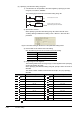
4) Usage range of index registers
The following table lists the usage range of index registers when setting
indexes in 32-bit range.
Since the specified index register (Zn) and next index register (Zn+1) are used
for index setting in 32-bit range, make sure not to overlap index registers being
used.
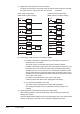
5) The following figure shows the examples of index setting and their actual
processing devices.
(With the setting of Z0 (32 bits) =100000 and Z2 (32 bits)=-20)
Figure 4.6-3 Ladder examples and actual processing devices
Setting value Index register Setting value Index register
Z0 Z0, Z1 Z10 Z10, Z11
Z1 Z1, Z2 Z11 Z11, Z12
Z2 Z2, Z3 Z12 Z12, Z13
Z3 Z3, Z4 Z13 Z13, Z14
Z4 Z4, Z5 Z14 Z14, Z15
Z5 Z5, Z6 Z15 Z15, Z16
Z6 Z6, Z7 Z16 Z16, Z17
Z7 Z7, Z8 Z17 Z17, Z18
Z8 Z8, Z9 Z18 Z18, Z19
Z9 Z9, Z10 Z19 Not applicable
Ladder example Actual processing device
X0
DMOV
EN ENO
ds
Z0K100000
DMOV
EN ENO
ds
Z2K-20
X1
MOV
EN ENO
ds
D13000Z2ZR1000Z0
X1
MOV
EN ENO
ds D12980ZR101000
Description
ZR1000Z0 ZR(1000+100000) ZR101000
D13000Z2 D(30-20) D12980