
Specifications


4.6 Index Setting
4-49
4
PROGRAM
CONFIGURATION
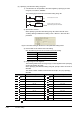
5) The following figure shows the examples of 32-bit index setting using 'ZZ' and
their actual processing devices.
(With the setting of Z0 (32 bits) =100000 and Z2 (32 bits)=-20)
Figure 4.6-5 Ladder examples and actual processing devices
6) Functions that can use 'ZZ'
32-bit index settings using 'ZZ' can be used in the following functions.
ZZn cannot be used individually such as 'DMOV K100000 ZZ0'. When setting a
value to index registers to specify a 32-bit index setting using 'ZZ', set a value to
Zn (Z0 to Z19).
ZZn cannot be entered individually in the functions.
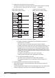
(c) 32-bit index setting for FXCPU
Combine index registers V (from V0) and Z (from Z0) for a 32-bit index setting.
V is used for high order and Z is used for low order. With the combination of the
specified Z and the corresponding V, the device can be used as a 32-bit register.
Note that the index setting is not applied by specifying the high order V.
Example: When specifying Z4, V4 and Z4 are used as a 32-bit register.
Ladder example Actual processing device
No. Description
1
Device specification with an instruction in a program
2
Monitoring device registrations
3
Device test
4
Device test with an execution condition
5
Setting monitoring conditions
6
Sampling trace (trace point (device specification), trace target
devices)
7
Data logging function (sampling interval (device specification),
logging target data)
Setting value Index register
Z0 V0, Z0
Z1 V1, Z1
Z2 V2, Z2
Z3 V3, Z3
Z4 V4, Z4
Z5 V5, Z5
Z6 V6, Z6
Z7 V7, Z7
X0
DMOV
EN ENO
ds
Z0K100000
DMOV
EN ENO
ds
Z2K-20
X1
MOV
EN ENO
ds
D13000Z2ZR1000ZZ0
X1
MOV
EN ENO
ds D12980ZR101000
Description
ZR1000Z0 ZR(1000+100000) ZR101000
D13000Z2 D(30-20) D12980