
Specifications


4-54
4.6 Index Setting
(c) Applying the index setting in the CALL instruction
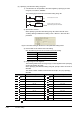
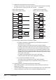
The pulse can be output by using edge relays (V) with the CALL instruction. Note that
the pulse cannot be output by the PLS, PLF, or pulse ( P) instruction.
[When using an edge relay] [When not using an edge relay]
(M0Z1 pulse is output normally.) (M0Z1 pulse is not output normally.)
(d) Device range check when the index setting is applied
1) For Basic model QCPU, High Performance model QCPU, Process CPU,
Redundant CPU, and FXCPU
The device range is not checked when the index setting is applied.
For Basic model QCPU, High Performance model QCPU, Process CPU, and
Redundant CPU, if the result of the index setting exceeds the device range
specified by a user, an error does not occur and the data are written to other
devices. (Note that if the result of the index setting exceeds the device range
specified by a user and the data are written to devices for the system, an error
occurs. (Error code: 1103))
For FXCPU, an operation error occurs. (Error code: 6706)
Create a program with caution when applying the index setting.
2) For Universal model QCPU, and LCPU
The device range is checked when the index setting is applied.
By changing the settings of the PLC parameter, the device range is not
checked.
(e) Switching between 16-bit and 32-bit range of the index setting
When switching between 16-bit and 32-bit range, check the positions of the index
setting in the program.
Since the specified index register (Zn) and next index register (Zn+1) are used for index
setting in 32-bit range, make sure not to overlap index registers being used.
SM400
MOV
EN ENO
ds
Z11
CALL
EN ENO
pP0
SM400
MOV
EN ENO
ds
Z11
CALL
EN ENO
pP0
X0Z1
EGP
EN ENO
d
OUT
EN ENO
dV0Z1
M0Z1
FEND
EN
ENO
RET
EN
ENO
SM400
MOV
EN ENO
ds
Z11
CALL
EN ENO
pP0
SM400
MOV
EN ENO
ds
Z11
CALL
EN ENO
pP0
X0Z1
PLS
EN ENO
d
M0Z1
FEND
EN
ENO
RET
EN
ENO