
Wiring Diagram – Configuration Diagrams
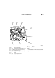

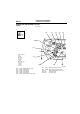
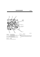
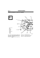
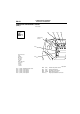
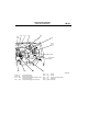


ENGINE AND TRANSMISSION
CONFIGURATION DIAGRAMS
80-15
NOTE: .
• On A/T only, the standard routing positions for the
corrugated tube and wiring harness are marked
by*.
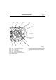
AC301133
AB
9
10
11
13
B-06
B-07
B-01
B-10X
B-14X
B-15X
B-16X
B-17X
B-18
Battery wiring
harness
B-19
B-20
B-21
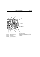
*
B-16X (4) Engine control relay
B-17X (4) A/C compressor relay
B-18 (6-B) Control wiring harness and battery wiring
harness combination
B-19 (10-GR) A/T control solenoid valve assembly
B-20 (10-B) Inhibitor switch <A/T>
B-21 (4-B) Engine control oxygen sensor (Front)
B-22 (1) Starter
B-23 (1-B) Starter
B-24 (1-B) Engine oil pressure switch
B-25 (1) Alternator
B-26 (4-GR) Alternator